EP0881138B1 - System mit hydraulischen Ventil mit Steuerknüppel und Stellglied dafür - Google Patents
System mit hydraulischen Ventil mit Steuerknüppel und Stellglied dafür Download PDFInfo
- Publication number
- EP0881138B1 EP0881138B1 EP98113315A EP98113315A EP0881138B1 EP 0881138 B1 EP0881138 B1 EP 0881138B1 EP 98113315 A EP98113315 A EP 98113315A EP 98113315 A EP98113315 A EP 98113315A EP 0881138 B1 EP0881138 B1 EP 0881138B1
- Authority
- EP
- European Patent Office
- Prior art keywords
- fluid
- axial
- valve
- follow
- operable
- Prior art date
- Legal status (The legal status is an assumption and is not a legal conclusion. Google has not performed a legal analysis and makes no representation as to the accuracy of the status listed.)
- Expired - Lifetime
Links
- 239000012530 fluid Substances 0.000 title claims description 211
- 230000007935 neutral effect Effects 0.000 claims description 38
- 238000004891 communication Methods 0.000 claims description 32
- 230000033001 locomotion Effects 0.000 claims description 31
- 230000004044 response Effects 0.000 claims description 30
- 230000005540 biological transmission Effects 0.000 claims description 16
- 238000006243 chemical reaction Methods 0.000 claims 1
- 230000007246 mechanism Effects 0.000 description 8
- 238000006073 displacement reaction Methods 0.000 description 6
- 230000006835 compression Effects 0.000 description 3
- 238000007906 compression Methods 0.000 description 3
- 230000001186 cumulative effect Effects 0.000 description 3
- 238000011144 upstream manufacturing Methods 0.000 description 3
- 230000004075 alteration Effects 0.000 description 2
- 230000003466 anti-cipated effect Effects 0.000 description 2
- 238000012937 correction Methods 0.000 description 2
- 238000010586 diagram Methods 0.000 description 2
- 238000001595 flow curve Methods 0.000 description 2
- 230000004048 modification Effects 0.000 description 2
- 238000012986 modification Methods 0.000 description 2
- 229910052761 rare earth metal Inorganic materials 0.000 description 2
- 150000002910 rare earth metals Chemical class 0.000 description 2
- 230000009467 reduction Effects 0.000 description 2
- 230000009471 action Effects 0.000 description 1
- 230000003190 augmentative effect Effects 0.000 description 1
- 230000008859 change Effects 0.000 description 1
- 238000010276 construction Methods 0.000 description 1
- 230000036461 convulsion Effects 0.000 description 1
- 230000008030 elimination Effects 0.000 description 1
- 238000003379 elimination reaction Methods 0.000 description 1
- 230000002706 hydrostatic effect Effects 0.000 description 1
- 230000003993 interaction Effects 0.000 description 1
- 238000005086 pumping Methods 0.000 description 1
- 230000000717 retained effect Effects 0.000 description 1
- 238000007789 sealing Methods 0.000 description 1
Images


Classifications
-
- B—PERFORMING OPERATIONS; TRANSPORTING
- B62—LAND VEHICLES FOR TRAVELLING OTHERWISE THAN ON RAILS
- B62D—MOTOR VEHICLES; TRAILERS
- B62D6/00—Arrangements for automatically controlling steering depending on driving conditions sensed and responded to, e.g. control circuits
-
- B—PERFORMING OPERATIONS; TRANSPORTING
- B62—LAND VEHICLES FOR TRAVELLING OTHERWISE THAN ON RAILS
- B62D—MOTOR VEHICLES; TRAILERS
- B62D1/00—Steering controls, i.e. means for initiating a change of direction of the vehicle
- B62D1/02—Steering controls, i.e. means for initiating a change of direction of the vehicle vehicle-mounted
- B62D1/22—Alternative steering-control elements, e.g. for teaching purposes
-
- B—PERFORMING OPERATIONS; TRANSPORTING
- B62—LAND VEHICLES FOR TRAVELLING OTHERWISE THAN ON RAILS
- B62D—MOTOR VEHICLES; TRAILERS
- B62D5/00—Power-assisted or power-driven steering
- B62D5/06—Power-assisted or power-driven steering fluid, i.e. using a pressurised fluid for most or all the force required for steering a vehicle
- B62D5/09—Power-assisted or power-driven steering fluid, i.e. using a pressurised fluid for most or all the force required for steering a vehicle characterised by means for actuating valves
- B62D5/093—Telemotor driven by steering wheel movement
- B62D5/097—Telemotor driven by steering wheel movement gerotor type
-
- Y—GENERAL TAGGING OF NEW TECHNOLOGICAL DEVELOPMENTS; GENERAL TAGGING OF CROSS-SECTIONAL TECHNOLOGIES SPANNING OVER SEVERAL SECTIONS OF THE IPC; TECHNICAL SUBJECTS COVERED BY FORMER USPC CROSS-REFERENCE ART COLLECTIONS [XRACs] AND DIGESTS
- Y10—TECHNICAL SUBJECTS COVERED BY FORMER USPC
- Y10T—TECHNICAL SUBJECTS COVERED BY FORMER US CLASSIFICATION
- Y10T137/00—Fluid handling
- Y10T137/8593—Systems
- Y10T137/86493—Multi-way valve unit
- Y10T137/86574—Supply and exhaust
- Y10T137/86638—Rotary valve
- Y10T137/86646—Plug type
- Y10T137/86662—Axial and radial flow
Definitions
- the present invention relates to fluid controllers of the type used to control the flow of fluid from a source of pressurized fluid to a fluid pressure actuated device, such as a steering cylinder for steering a vehicle. More particularly, the present invention relates to such a steering system having both a normal input, such as the vehicle steering wheel, and an auxiliary input, such as a joystick.
- a typical fluid controller of the type to which the present invention relates includes a housing which defines various fluid ports, and further includes a fluid meter, a valve means, and an arrangement for imparting follow-up movement to the valve means, in response to the flow of fluid through the fluid meter.
- the flow through the controller valve means is directly proportional to the area of variable flow control orifices in the main fluid path, the area of the flow control orifices in turn typically being proportional to the rate at which the steering wheel is rotated.
- a typical application for a full-fluid-linked steering system of the type to which the present invention relates would be a vehicle such as is used on a construction site.
- a vehicle such as is used on a construction site.
- Such a vehicle is used primarily in one of two operating modes: first, the vehicle is driven in a "roading" mode, i.e., it is being driven on the road, at normal roading speeds, in order to reach the work site.
- the vehicle is operated in a working mode, on the work site, and performing operations such as moving a pile of dirt, etc.
- gain rate refers to the rate of change of steered wheel position for a given amount of steering input.
- One known, commercially available steering system includes a conventional steering control unit, which receives an input from the steering wheel, and a separate, electrically actuated proportional flow control valve, which receives an input by means of a joystick.
- the output of both the steering control valve and the proportional valve goes to the steering cylinder in a parallel arrangement.
- There is no interface between the two subsystems i.e., the one controlled by the wheel, and the other controlled by the joystick), or any ability for the flow output of one subsystem to be augmented by flow output from the other subsystem.
- One of the disadvantages of known steering wheel/joystick systems is the complication, and expense of coordinating the portion of the system operated by the steering wheel with the portion of the system operated by the joystick.
- the operator is steering by means of the joystick, and then begins to rotate the steering wheel, there must be logic or some sort of interface provided to determine whether the steering wheel input or the joystick input would take precedence.
- the vehicle is operating above a predetermined vehicle speed, or operating above a predetermined transmission gear, it may be desirable, or even legally required, to prevent steering in response to the joystick input, and permit the operator to steer only by means of the steering wheel.
- U.S. Patent Nos. 5,016,672 and 5,115,640 both of which are assigned to the assignee of the present invention, disclose fluid controllers in which the valve means, comprising a spool and sleeve, can be actuated by rotation of a steering wheel in the conventional manner.
- the sleeve valve may be moved axially, relative to the spool valve, to define an auxiliary fluid path. Control of the axial position of the sleeve valve is by means of a pilot pressure chamber adjacent one axial end of the sleeve valve, the pressure in the pilot pressure chamber being controlled by a solenoid valve.
- a system for controlling the flow of fluid from a source of pressurized fluid to a fluid pressure operated device is of the type disclosed in US-A-5 016 672 corresponding to the preamble of claim 1, including a controller operable to control the flow of fluid from the source to the device in response to movement of a first input means.
- the controller is of the type including housing means defining an inlet port, a return port, and first and second control fluid ports for connection to the device.
- First valve means is disposed in the housing means, and the first valve means and the housing means cooperate to define a first fluid path providing fluid communication from the inlet port to the first control fluid port, and from the second control fluid port to the return port, in response to the movement of said first input means.
- Second valve means is disposed in the housing means, and the second valve means and the housing means cooperate to define a second fluid path providing fluid communication from the inlet port to the first control fluid port , and from the second control fluid port to the return port in response to movement of a second input means.
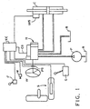
- FIG. 1 is a somewhat pictorial schematic of the vehicle steering system of the present invention.
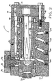
- FIG. 2 is a fragmentary, axial cross-section of the fluid controller shown schematically in FIG. 1.
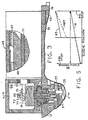
- FIG. 3 is a view, partly in plan view, and partly in axial cross-section, of the actuator associated with the fluid controller shown in FIG. 2, and on the same scale as FIG. 2.
- FIG. 4 is a transverse cross-section taken on line 4-4 of FIGS. 2 and 3, and on the same scale as FIG. 3.
- FIG. 5 is a graph of biasing force versus sleeve position, illustrating one aspect of the present invention.
- FIG. 6 is an overlay view of the valving used in the fluid controller shown in FIG. 2, but on a larger scale than in FIG. 2, and with the valving shown in the rotary, neutral, and neutral axial positions.
- FIG. 7 is an enlarged, fragmentary, overlay view, similar to FIG. 6, but with the valving in a rotary operating and axial operating position.
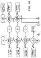
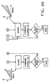
- FIG. 8 is a block diagram of a control logic system to be utilized in conjunction with the electronic controller shown in the schematic of FIG. 1.
- FIG. 1 is a somewhat pictorial schematic of a vehicle hydrostatic power steering system of the type to which the present invention relates.
- the system includes a fluid pump P which receives fluid from a system reservoir R, and directs pressurized fluid to a fluid controller, generally designated 11.
- the controller 11 directs metered, pressurized fluid to a steering cylinder C, normally in response to rotation of a steering wheel W.
- an operator's seat Disposed adjacent the steering wheel W, and typically within the cab of a vehicle such as a tractor or combine, is an operator's seat, generally designated S. Also disposed adjacent the wheel W in the cab is a transmission gear shift G, a mode select switch M, and a joystick J. Attached to the steering cylinder C is a steered wheel sensor WS. In addition, operably associated with the steering wheel W is a wheel position sensor PS. The operator's seat S includes a switch, the function of which is to indicate the presence or absence of the operator, and hereinafter the switch in the operator's seat will be designated S. Similarly, the transmission gear shift G is equipped to provide a signal indicative of the particular transmission gear which has been selected, and the device which generates the signal will hereinafter be designated G.
- the signals from the gear sensor G, the seat switch S, the position sensor PS, the mode switch M, and the joystick J are all inputs to an electronic controller EC.
- the signals from the five input elements will bear the reference numerals of their respective elements.
- the electronic controller EC is also in communication with the fluid controller 11 by means of a command signal CS. The way in which the various input signals described above are utilized in the system by the electronic controller EC will be described in greater detail subsequently.
- the operator can control the flow of pressurized fluid from the pump P through the controller 11 to the steering cylinder C either by means of the steering wheel W or the joystick J.
- the steering wheel W is typically used by the operator in the "roading" mode, while the joystick is typically used by the operator when the vehicle is in the working mode.
- the mode select switch M is included to permit the operator to select, manually, between the high and low gain rates, as will be described in greater detail subsequently.
- the fluid controller 11 may be of the general type illustrated and described in above mentioned U.S. Patent Nos. 5,016,672 and 5,115,640.
- the fluid controller 11 comprises several sections, including a valve housing section 13, a wear plate 15, a section comprising a fluid meter 17, and an endcap 19. These sections are held together in tight sealing engagement by means of a plurality of bolts 21, which are in threaded engagement with the valve housing section 13.
- the valve housing section 13 defines a fluid inlet port 23, a fluid return port 25, a pair of control (cylinder) fluid ports 27 and 29, and a load sensing fluid port 31.
- the valve housing section 13 also defines a valve bore 33, and rotatably disposed therein is the controller valving which comprises a primary, rotatable valve member 35 (also referred to hereinafter as the "spool"), and a cooperating, relatively rotatable follow-up valve member 37 (also referred to hereinafter as the "sleeve").
- the controller valving which comprises a primary, rotatable valve member 35 (also referred to hereinafter as the "spool"), and a cooperating, relatively rotatable follow-up valve member 37 (also referred to hereinafter as the "sleeve").
- a primary, rotatable valve member 35 also referred to hereinafter as the "spool”
- a cooperating, relatively rotatable follow-up valve member 37 also referred to hereinafter as the "sleeve”
- the spool 35 and the sleeve 37 will be described in greater detail subsequently.
- the fluid meter 17 may be of the type well known in the art, and in the subject embodiment, includes an internally-toothed ring member 41, and an externally-toothed star member 43.
- the star member 43 is eccentrically disposed within the ring member 41, for orbital and rotational movement relative thereto.
- the star member 43 is in splined connection with the rearward end of a main driveshaft 45, which defines, at its forward end, an enclosed, elongated slot 47. Extending transversely through the slot 47 is a drive pin 49 which permits driving connection between the shaft 45 and the sleeve 37.
- the forward end of the driveshaft 45 it is preferable for the forward end of the driveshaft 45 to define the enclosed slot 47, rather than the conventional, open-ended arrangement, thus providing a greater total torque transmitting capability through the shaft 45 and the pin 49.
- the diameter of the driveshaft can be reduced, and therefore, the radial thickness of the spool 35 can be increased, thus facilitating the location of check valves within the spool, in accordance with the teachings of U.S. Patent No. 5,101,860, assigned to the assignee of the present invention.
- the ends of the drive pin 49 pass through a pair of pin openings 51 defined by the spool 35 (see FIG. 6), and are received in relatively close-fit openings in the sleeve 37.
- pressurized fluid flows through the various passages and ports defined by the spool 35 and sleeve 37, then flows through the fluid meter 17, causing orbital and rotational movement of the star 43, within the ring 41.
- Such movement of the star 43 causes rotational follow-up movement of the sleeve 37, by means of the driveshaft 45, and drive pin 49, to maintain a particular relative rotational displacement (deflection) between the spool 35 and sleeve 37.
- the particular relative displacement (referred to hereinafter as a "rotary operating position"), is generally proportional to the rate of rotation of the steering wheel W, i.e., the rate of rotation of the spool 35.
- a neutral (rotary) centering spring arrangement comprising a torsional spring 53, which surrounds a forward, reduced-diameter portion of the sleeve 37.
- the spool 35 and sleeve 37 define overlapping windows 55 into which the opposite ends of the torsion spring 53 extend, and are seated therein.
- the circumferential extent of the windows 55 is a maximum when the spool and sleeve are in the rotary neutral position shown in FIGS.
- the windows decrease in the circumferential dimension, thus loading the spring 53, as the spool and sleeve are displaced from the rotary neutral position.
- the function of the torsion spring 53 is to bias the sleeve 37 toward the "rotary neutral position" (as that term will be defined in connection with FIG. 6) relative to the spool 35.
- the valve bore 33 of the valve housing section 13 defines a plurality of annular fluid chambers surrounding the sleeve 37, to provide fluid communication between the various ports (23 through 31) and the outer surface of the sleeve 37.
- An annular chamber 23c receives pressurized fluid from the inlet port 23, while an annular chamber 25c communicates return fluid to the return port 25.
- Annular chambers 27c and 29c provide fluid communication to and from the control ports 27 and 29, respectively.
- annular chamber 31c is in communication with the load signal fluid port 31.
- the valve housing section 13 defines a plurality of axial bores 61 (only one of which is shown in FIG. 2), each of which is in open communication with one of the fluid ports 59.
- the valve housing section 13 further defines a pair of radial bores 63L and 63R, providing communication between each of the axial bores 61 and the valve bore 33, for purposes which are well known to those skilled in the art, and will be described in greater detail subsequently.
- the spool 35 is also rotated clockwise, as viewed by the vehicle operator (moves "downward” from the position shown in FIG. 6) opening a series of variable flow control orifices between the spool 35 and the sleeve 37.
- These orifices which will be described in greater detail subsequently, permit fluid communication from the inlet port 23 through the valving, then through the radial bores 63L and some of the axial bores 61 to the expanding volume chambers 57 of the fluid meter 17.
- Fluid flowing from the contracting volume chambers of the meter 17 (“metered fluid”) then flows through the other of the axial bores 61, through the radial bores 63R, and through the valving, then out through the cylinder port 27. Fluid returning from the steering cylinder C enters the cylinder port 29, then flows through the valve, and then out to the return port 25.
- the fluid controller 11 may be of the general type illustrated and described in above mentioned U.S. Patent No. 5,115,640.
- the fluid controller 11 of the present invention is similar to the above-cited patent in that the controller valving provides both the main fluid path (MFP) just described, as well as a parallel, or auxiliary, fluid path (AFP).
- MFP main fluid path
- AFP auxiliary, fluid path
- the "parallel" fluid path permits fluid communication from the inlet port 23 into the valving, then out cylinder port 27, in parallel with the main fluid path, but with the "parallel" fluid path not flowing through the fluid meter 17.
- the fluid controller 11 of the present invention differs from the controllers of the above-mentioned patents in several significant ways.
- the parallel fluid path is designed to communicate a substantial fluid flow, and preferably, a flow greater than the main fluid path.
- the axial actuation of the sleeve 37 be accomplished by a direct mechanical actuation, rather than by a pilot fluid pressure acting on the ends of the sleeve, as in the mentioned patents.
- FIGS. 3 and 4 in conjunction with FIG. 2, there will be described one embodiment of an actuator mechanism to be used in the direct mechanical actuation of the sleeve 37, in accordance with the present invention.
- the actuator mechanism illustrated and described herein is by way of example only, and except as set forth in the appended claims, the present invention is not limited to any particular type or configuration of actuator mechanism.
- the actuator mechanism of the present invention comprises a linear actuator, generally designated 65.
- the linear actuator 65 includes an electromagnetic coil 67, which is energized by an electrical input signal (command signal CS) from the electronic controller EC.
- command signal CS electrical input signal
- the linear actuator 65 has a definite, physical neutral position, and when the coil 67 is energized, the magnetic field in the rare earth magnet 69 exerts a fairly constant force of approximately 5 lb. (2.25 kg.) on the armature 71, biasing the armature either forwardly or rearwardly in FIG. 3, depending upon the polarity of the command signal CS to the actuator 65.
- the actuator 65 is able to move the armature 71, from the neutral position, up to approximately 13 mm (one-half inch) in either direction.
- the output end (left end in FIG. 3) of the armature member 71 is pivotally connected to a crank mechanism, generally designated 73, disposed within a crank housing 74, which includes a drag link 75.
- the drag link 75 includes an elongated, horizontally oriented portion 77, which is disposed about, and in engagement with, a rotatable actuator member 79.
- the actuator member 79 is rotatable about its axis of rotation A, and is rotatably supported within an actuator housing 81, the housing 81 defining external threads, and being in threaded engagement with an internally threaded opening 83 defined by the valve housing section 13.
- the actuator member 79 is externally threaded, and the horizontal portion 77 of the drag link 75 is retained on the actuator member 79 by means of a nut 85.
- the actuator member 79 includes, at its lower end, a drive pin 87 which, preferably, is in a press fit in an opening defined by the member 79.
- the drive pin 87 is disposed eccentrically, relative to the axis of rotation A, for reasons to be explained subsequently.
- the drive pin 87 extends into an annular groove 89 defined by the sleeve 37, whereby rotation of the actuator member 79 in a clockwise direction (looking down on FIG. 4) will move the sleeve 37 forward (to the left in FIG. 2), and from the neutral axial position shown in FIG. 6 to the axial operating position shown in FIG. 7.
- the wear plate 15 defines a plurality (only one of which is shown in FIG. 2) of cylindrical, axially oriented openings, within each of which is disposed a helical compression spring 93.
- the axial biasing forces exerted on the sleeve 37 will be described. In the subsequent description, the specific biasing forces are by way of example only, and are in no way limiting.
- the torsional centering spring 91 exerts a biasing force of about 5 lb. (2.25 kg.), by means of the actuator member 79, tending to bias the sleeve rearwardly (to the right in FIG. 2).
- the wrap of the spring 91 is such that, as the sleeve 37 is moved forwardly (to the left in FIG. 2), the biasing force in the sleeve 37 gradually increases to about 10 lb. (4.5 kg.) when the sleeve engages the pin stop 49.
- the torsional spring 91 gradually unwinds, until it exerts a substantially zero rearward biasing force on the sleeve 37 just as the sleeve reaches the pin stop in its rearwardmost position.
- the helical compressions springs 93 do not exert any axial force on the sleeve 37, whenever the sleeve is between its axial neutral position and its forward position. However, whenever the sleeve is displaced from its axial neutral position, rearwardly, there is instantly an axial force of about 10 lb. (4.5 kg.) tending to bias the sleeve to the left in FIG. 2, toward the neutral axial position. As the sleeve 37 moves further rearwardly, the biasing force increases until, just as the sleeve reaches its rearwardmost position and engages the pin stop 49, the axial force exerted by the springs 93 reaches about 15 lb. (6.75 kg.).
- the crank mechanism 73 multiplies the force output of the actuator 65 by a factor of about 4:1, so that the 5 lb. (2.25 kg.) force of the actuator results in an axial force on the sleeve of about 20 lb. (9.0 kg.).
- a sleeve position sensor generally designated 95.
- the sensor 95 senses the axial position of the armature member 71, and sends an appropriate signal back to the electronic controller EC.
- the electronic controller EC commands a desired axial position of the sleeve 37 by sending the appropriate command signal CS to the linear actuator 65, which then directly, mechanically moves the sleeve 37 in the appropriate axial direction.
- a signal is being sent back to the electronic controller EC until the "loop" is closed and the error (difference between desired position and actual position) is reduced to zero.
- the sleeve position sensor 95 could take many different forms, and could be located in several different locations.
- the position sensor 95 could be disposed within the valve housing section 13, wherein it would directly, physically sense the position of the sleeve 37.
- the sleeve's position sensor could be operatively associated with some portion of the crank mechanism 73, and could comprise something such as a rotary potentiometer, such that it would sense the rotary position of the actuator member 79, and send a signal to the electronic controller EC, which would include software capable of converting the rotary position of the actuator member 79 into the axial position of the sleeve 37.
- the sleeve position sensor 95 can be operatively associated with some portion of the actuator mechanism.
- the selection of an appropriate sleeve position sensor 95, as well as any appropriate software to be included in the electronic controller EC is well within the ability of those skilled in the art. Although it is preferred to include such a sensor, thereby closing the loop, it is not an essential feature of the invention, and the particular sensor and software chosen is not essential.
- FIGS. 6 and 7 are intended to illustrate primarily the interface between the outer cylindrical surface of the spool 35 (dashed lines) and the cylindrical inner surface of the sleeve 37 (solid lines). As a result, certain structural features which appear only on the outer surface of the sleeve will not be shown in FIGS. 6 and 7. It should be noted that in FIG. 6, the spool 35 and sleeve 37 are in a relative axial position corresponding to the neutral axial position shown in FIG. 2, and are in a relative rotational position corresponding to the rotary neutral position, also as shown in FIG. 2.
- the spool 35 defines a pair of annular meter grooves 97L and 97R, which are axially aligned with the radial bores 63L and 63R, respectively.
- a pressure passage 99L In communication with the meter groove 97L is a pressure passage 99L, and in communication with the meter groove 97R is a pressure passage 99R.
- Circumferentially adjacent each of the pressure passages 99L is a return passage 101L, and circumferentially adjacent each of the pressure passages 99R, but in the opposite direction therefrom, is a return passage 101R.
- the spool 35 defines the pin openings 51, and the return passages 101L and 101R, and the pin openings 51 extend to the interior of the spool 35.
- the sleeve 37 defines a pair of pressure ports 103, disposed on the reference plane RP. Disposed somewhat to the left of the pressure ports 103 is a plurality of load sensing ports 105, which are in open communication with the annular load sensing chamber 31c defined by the valve housing section 13.
- the sleeve 37 further defines an operating port 107L disposed adjacent the return passage 101L, and an operating port 107R, disposed adjacent the return passage 101R.
- the sleeve 37 defines a plurality of meter ports 109L in continuous fluid communication with the meter groove 97L, and a plurality of meter ports 109R, in continuous fluid communication with the meter groove 97R.
- Each of the meter ports 109L and 109R includes a generally rectangular opening defined by the outer surface of the sleeve (not shown herein), the purpose of the rectangular openings being to permit commutating fluid communication between the meter ports 109L and 109R, and the radial bores 63L and 63R, respectively, even when the sleeve 65 has been axially displaced in one direction or the other from the neutral axial position shown in FIG. 6.
- the rectangular openings described above are illustrated in greater detail in above mentioned U.S Patent No. 5,115,640.
- the sleeve 37 defines a plurality of tank ports 111, each of which is in continuous communication with the return port 25 (shown in FIG. 2) by means of the annular chamber 25c. All of the ports and passages described thus far relate to the rotary valving which, because it is generally well known to those skilled in the art, will be described only briefly hereinafter.
- Fluid flowing through the A1r r orifice then flows into the meter groove 97L, then through the meter ports 109L to the fluid meter 17 (in the manner described previously), returning from the fluid meter 17 and flowing through the meter ports 109R and into the meter groove 97R.
- This "metered fluid” then enters the pressure passages 99R, which are now overlapping the operating ports 107R to define a variable flow control orifice (A4r). Metered fluid flows from the A4r orifice into the annular chamber 27c, and from there to the cylinder port 27c, then to the steering cylinder C.
- Fluid returning from the exhaust side of the steering cylinder C flows to the cylinder port 29, then into the annular chamber 29c, and then through an A5r orifice defined by the overlap of the operating ports 107L and the return passages 101L.
- This return fluid then flows through the interior of the spool 35, then radially out through the pin openings 51 and tank ports 111 to the annular chamber 25c, and then to the return port 25, and finally, to the system reservoir R.
- the above-described flow path thus comprises the "main fluid path" defined when the spool and sleeve are displaced from the neutral rotary position to a rotary operating position. It should be noted that in FIG.
- valve members be laid out such that axial actuation thereof results in a parallel fluid path being defined within the fluid controller, with the parallel path preferably being separate and distinct from the main fluid path (just described) which is defined in response to relative rotation of the spool and sleeve.
- parallel path preferably being separate and distinct from the main fluid path (just described) which is defined in response to relative rotation of the spool and sleeve.
- each of the return passages 101L disposed to the right and upward from each of the return passages 101L is an area of ports and passages (most of which extend circumferentially) which have not yet been described in detail, and which comprise the axial valving.
- the axial valving will be described in some detail, and it should be noted that, although the spool and sleeve in FIG. 7 have been rotatably displaced from the neutral rotary position the axial valving would operate in the same way in FIG. 7, regardless of the relative rotary position. Thus, it is one important aspect of the present invention that the rotary valving operates independently of the instantaneous axial position of the sleeve 37, while the axial valving operates independently of the instantaneous rotary position of the spool 35 and sleeve 37.
- the spool 35 defines a pair of circumferentially-extending pressure passages 115L and 115R, which are interconnected by an axially-extending passage 117.
- the spool 35 further defines a pair of circumferentially-extending operating passages 119L and 119R, which are also interconnected through the axial passage 117.
- Disposed axially outward therefrom, the spool defines a pair of circumferentially-extending return passages 121 L and a pair of circumferentially-extending return passages 121R.
- the sleeve 37 defines a pair of circumferentially-extending pressure ports 123, a pair of circumferentially-extending operating ports 125L, and a pair of circumferentially-extending operating ports 125R.
- the pressure ports 123 are axially centered between the adjacent pressure passages 115L and 115R.
- the operating ports 125L are axially centered between the operating passage 119L and the return passage 121L.
- the operating ports 125R are axially centered between the operating passages 119R and the return passages 121R.
- the pressure ports 123 begin to overlap the pressure passages 115L, the cumulative overlap therebetween defining an A1a orifice, the designation "a" after the "A1” merely indicating an orifice formed in response to relative axial movement of the spool and sleeve.
- Pressurized fluid entering the pressure passages 115L then flows through the passages 117 and into the operating passage 119R.
- the passages 119R are now in fluid communication with the operating ports 125R, the cumulative overlap therebetween defining an A4a orifice.
- the fluid returning from the steering cylinder C flows through the annular chamber 29c, and from there, the fluid flows through an A5a orifice defined by the cumulative overlap between the operating ports 125L and the return passages 121L. This return fluid then flows to the interior of the spool 35, and from there to the system reservoir in the manner described previously.
- the parallel (auxiliary) flow path be capable of communicating a substantial flow of fluid, i.e., such that the flow through the parallel path defined by the axial valving is, in and of itself, sufficient to perform a steering operation, in the absence of any flow through the main fluid path.
- the flow through the main fluid path in response to operation of the rotary valving, constitutes a relatively small flow, although it will be understood by those skilled in the art that the relatively small flow through the main fluid path must still be sufficient to achieve normal steering.
- the fluid meter 17 and the various orifices in the rotary valving are sized such that the flow through the main fluid path is appropriate for performing a normal steering operation in the roading mode.
- the various flow control orifices which comprise the axial valving are sized such that the flow through the parallel fluid path provides a relatively large flow, i.e., a flow which is large relative to that in the main fluid path.
- the flow control orifices in the axial valving are sized such that the relatively large flow through the parallel fluid path is appropriate for operation in the working mode, as that term was described previously.
- the relatively large flow through the parallel fluid path may be in the range of 2-3 times the flow through the main fluid path.
- the fluid meter 17 can be sized for a relatively small displacement, as was previously mentioned.
- the presence of a relatively small fluid meter makes it possible to manually steer, i.e., the operator rotates the steering wheel W to achieve actuation of the rotary valving, and the fluid meter 17 operates in the manner of a hand pump, pumping pressurized fluid to the steering cylinder C as is now well known in the art.
- the spool and sleeve While operating in the manual steering mode, the spool and sleeve are in the rotary operating position as shown in FIG. 7, but in the neutral axial position as shown in FIG. 6.
- the neutral axial position would typically be accomplished by the linear actuator 65 receiving a zero or "OFF" input signal, with the centering spring 91 and the compression spring 93 then returning the sleeve 37 to its neutral axial position as shown in FIG. 2.
- the configuration of the ports and passages required to accomplish wide angle steering is such that the wide angle feature cannot be readily combined with axial valving of the type which would accommodate a separate, independent input, such as joystick steering. More specifically, it is not physically possible to combine the wide angle feature and axial valving feature in a controller of the normal size, i.e., having a spool and sleeve which are of a normal, reasonable size.
- the steering system and fluid controller of the subject embodiment make it possible to have either normal rotary steering (rotary valving), or separate, independent joystick steering (axial valving), both of which have already been described, or alternatively, to have what will be referred to hereinafter as "electronic wide angle" steering, which will be described in greater detail subsequently, in connection with the logic of FIG. 8.
- electronic wide angle steering is to achieve substantially the same flow curve in a controller having only about twenty or twenty-two degrees of rotary displacement, as would be possible in the wide angle unit of above-mentioned U.S. Patent No. 5,080,135.
- the term "flow curve” refers to a curve or graph of Q (flow) versus d ⁇ /dt (rate of rotary deflection of spool and sleeve).
- control logic system shown in block diagram form in FIGS. 8A and 8B, another important aspect of the present invention will be described. It should be understood that the control logic illustrated in FIGS. 8A and 8B does not relate to the operating situation wherein the only input is by means of the steering wheel W. Instead, the control logic relates only to the situation wherein there is an additional input to the electronic controller EC, such as by means of the joystick J.
- FIG. 8A it should be noted that there are six different inputs to the control logic, two of which are the inputs from the joystick J and the steering wheel W.
- wheel velocity signal from the wheel position sensor PS is shown in two different places. It should further be noted that, as is described in above-mentioned U.S. Patent No. 5,115,640, it would be typical to differentiate the signal from the wheel position sensor PS to obtain the actual velocity signal (dPS/dt) which serves as the input shown in FIG. 8A.
- the control logic first considers the presence or absence of the vehicle operator. On either “side” of the logic (i.e., joystick or steering wheel input), if the input signal from the operator's seat S indicates that the operator is not present (NO), the electronic controller EC sends an appropriate signal to the linear actuator 65 whereby the sleeve 37 moves to the neutral axial ("N.A.") position.
- the logic i.e., joystick or steering wheel input
- the electronic controller EC sends an appropriate signal to the linear actuator 65 whereby the sleeve 37 moves to the neutral axial ("N.A.") position.
- the next step in the logic is to consider the signal from the pressure switch on the pump P. If the signal indicates that the hydraulic power is not on (“NO”), the sleeve 37 is permitted or commanded to its neutral axial position ("N.A.”) in the same manner as described previously.
- the next step in the logic is to consider the input signal from the transmission gear shift G. If the input signal G indicates that the transmission is in one of the "roading” gears (“YES”), the appropriate operation is an interrupt or an "OVERRIDE".
- interrupt and “override” should be understood to mean and include either a complete cut-off of the signal from the electronic controller EC, which drives the sleeve 37 to an axially displaced position, or merely a reduction in the gain of the command signal CS from the electronic controller EC.
- the appropriate operation would typically be a complete override, such that the joystick J would thereafter be unable to . displace the spool and sleeve from the neutral axial position, and steering could be accomplished in response to only the rotation of the steering wheel W.
- the logic proceeds to the next step in which the logic receives the input signal PS, representative of steering wheel position, or more likely, steering wheel speed. If the input signal PS indicates that the steering wheel W is being rotated at a rate exceeding a predetermined minimum (e.g., 5 rpm), and the result of the decision block is "YES”, the resulting operation is again an "OVERRIDE", which again can be either a complete cut-off of the command signal or a reduction in the gain thereof.
- a predetermined minimum e.g., 5 rpm
- the logic proceeds to an operation "SHAPE” in which the input signal from the joystick J is "shaped” to give the appropriate, predetermined relationship of flow ("Q") in the parallel path versus the rate of movement of the joystick J, i.e., d ⁇ /dt.
- the next step is to generate a corresponding command signal ("COMMAND SIGNAL CS") which is transmitted from the electronic controller EC to drive the sleeve 37 to the appropriate position.
- An additional input to the control logic is the feedback signal from the controller 11, and in the subject embodiment, from the linear actuator 65. If this feedback signal indicates that the sleeve 37. moved (“YES”), the operation of the control logic comes to an end. If not (“NO”), the control logic loops back to a point upstream of the "SHAPE" operation.
- the logic does not initially receive the input signal G from the transmission gear shift (i.e., the logic does not really care which gear in the transmission is engaged).
- the logic next proceeds to the "SHAPE” operation in which the logic considers the rate of rotation of the steering wheel W ("d ⁇ /dt"), and the input signal G from the transmission gear shift and "shapes" the input signal to the electronic controller EC to command the sleeve 37 to an appropriate axial position.
- the command signal CS from the electronic controller EC can be shaped in any manner desired, to provide any desired relationship of total flow ("Q") to steering wheel rotation rate "d ⁇ /dt".
- the next step in the logic is to generate the actual command signal ("COMMAND SIGNAL CS") which is transmitted to the linear actuator 65.
- the logic considers the feedback signal from the sleeve 37, and if the sleeve has moved ("YES"), the control logic comes to an end. If the sleeve has not moved (“NO”), the logic loops back to a point upstream of the "SHAPE" operation.
- the total system response time will have a bandwidth in the range of about 20 to 40 Hertz, i.e., the controller and logic together will be able to accomplish in the range of about 20 to 40 physical changes or corrections, per second, of the position of the sleeve.
- Another aspect of improved system response time relates to the point within the overall system at which the logic loop is "closed". It has been known previously to close the loop by sensing the steered wheel position ("WS”), but with the present invention, sensing sleeve position and providing feedback to the logic indicating that position, ("upstream" of steered wheel position) makes it possible for the system to respond more quickly to desired changes in steered wheel position.
- WS steered wheel position
Landscapes
- Engineering & Computer Science (AREA)
- Chemical & Material Sciences (AREA)
- Combustion & Propulsion (AREA)
- Transportation (AREA)
- Mechanical Engineering (AREA)
- Steering Control In Accordance With Driving Conditions (AREA)
- Power Steering Mechanism (AREA)
- Mechanical Control Devices (AREA)
Claims (34)
- System zum Steuern des Fluidstroms von einer Quelle (P) von unter Druck stehendem Fluid zu einer fluiddruckbetätigten Vorrichtung (C), wobei das System versehen ist mit einem Steuergerät (11), welches betätigbar ist, um den Fluidstrom von der Quelle (P) zu der Vorrichtung (C) in Ansprechen auf eine Bewegung einer ersten Eingabeanordnung (W) zu steuern, wobei das Steuergerät (11) versehen ist mit einer Gehäuseanordnung (13), die einen Einlassanschluss (23), einen Rücklaufanschluss (25) und einen ersten (27) und einen zweiten (29) Steuerfluidanschluss zur Verbindung mit der Vorrichtung (C) aufweist, wobei in der Gehäuseanordnung eine erste Ventilanordnung (35, 37) angeordnet ist, und wobei die erste Ventilanordnung und die Gehäuseanordnung zusammenwirken, um einen ersten Fluidweg (MFP) zu bestimmen, der für eine Fluidverbindung von dem Einlassanschluss (23) zu dem ersten Steuerfluidanschluss (27) und von dem zweiten Steuerfluidanschluss (29) zu dem Rücklaufanschluss (25) in Ansprechen auf die Bewegung der ersten Eingabeanordnung (W) sorgt, wobei eine zweite Ventilanordnung (35, 37) in der Gehäuseanordnung (13) vorgesehen ist, und die zweite Ventilanordnung und die Gehäuseanordnung zusammenwirken, um einen zweiten Fluidweg (AFP) zu bestimmen, der für eine Fluidverbindung von dem Einlassanschluss (23) zu dem ersten Steuerfluidanschluss (27) und von dem zweiten Steuerfluidanschluss (29) zu dem Rücklaufanschluss (25) in Ansprechen auf eine Bewegung einer zweiten Eingabeanordnung (J) sorgt, dadurch gekennzeichnet, dass:(a) die zweite Eingabeanordnung (J) ein elektromagnetisches Betätigungsglied (65) aufweist, welches betätigbar ist, um die zweite Ventilanordnung (37) in Ansprechen auf das Empfangen eines vorbestimmten elektrischen Eingangssignals (CS) zu betätigen;(b) eine Erfassungsanordnung (S, PS, G, P) vorgesehen ist, die betätigbar ist, um das Vorhandensein eines vorbestimmten Zustands zu erfassen und ein Unterbrechungssignal in Ansprechen auf den vorbestimmten Zustand zu erzeugen; und(c) eine Unterbrechungsanordnung vorgesehen ist, die in Ansprechen auf das Unterbrechungssignal betätigbar ist, um das vorbestimmte elektrische Eingangssignal (CS) zu unterbrechen.
- System nach Anspruch 1, gekennzeichnet durch eine fluidbetätigte Anordnung (17), die die erste Ventilanordnung (35, 37) zu einer Nachlaufbewegung veranlasst, die proportional zu dem Volumen des Fluidstroms durch den ersten Fluidweg (MFP) ist, wenn die erste Ventilanordnung in einer Arbeitsstellung (FIG. 7) steht.
- System nach Anspruch 2, dadurch gekennzeichnet, dass der zweite Fluidweg (AFP), der von der zweiten Ventilanordnung (35, 37) bestimmt wird, die fluidbetätigte Anordnung (17) nicht beinhaltet wenn die zweite Ventilanordnung in einer Arbeitsstellung (FIG. 7) steht.
- System nach Anspruch 3, dadurch gekennzeichnet, dass die Strömungskapazität des ersten Fluidwegs (MFP) relativ kleiner ist, wenn die erste Ventilanordnung (35, 37) in der Arbeitsstellung steht, und dass die Strömungskapazität des zweiten Fluidwegs (AFP) relativ größer ist, wenn die zweite Ventilanordnung (35, 37) in der Arbeitsstellung steht.
- System nach einem der vorhergehenden Ansprüche, dadurch gekennzeichnet, dass der vorbestimmte Zustand eine Bewegung der ersten Eingabeanordnung (W) bei einer Rate ist, die eine vorbestimmte Minimalrate übersteigt.
- System nach einem der vorhergehenden Ansprüche, dadurch gekennzeichnet, dass die Quelle (P) für unter Druck stehendes Fluid eine Druckerfassungsanordnung (P) umfasst, die betätigbar ist, um den Druck des von der Quelle abströmenden Fluids zu erfassen, wobei der vorbestimmte Zustand das Erfassen eines Fluiddrucks unterhalb eines vorbestimmten Minimaldrucks ist.
- System nach einem der vorhergehenden Ansprüche, dadurch gekennzeichnet, dass es zur Verwendung bei einem von einem Fahrzeugbediener zu bedienenden Fahrzeug ausgelegt ist, wobei das System ferner eine Erfassungsanordnung (S) umfasst, die betätigbar ist, um die Anwesenheit oder die Abwesenheit des Fahrzeugbedieners zu erfassen, wobei der vorbestimmte Zustand die Abwesenheit des Fahrzeugbedieners ist.
- System nach einem der Ansprüche 1 bis 6, dadurch gekennzeichnet, dass das System zur Verwendung bei einem Fahrzeug ausgelegt ist, das eine Antriebsmaschine und ein Getriebe, eine Anordnung (G), die betätigbar ist, um ein Getriebeübertragungsverhältnis zu wählen, sowie eine Anordnung aufweist, die betätigbar ist, um das gewählte Getriebeübertragungsverhältnis zu erfassen, wobei der vorbestimmte Zustand die Wahl eines Getriebeverhältnisses oberhalb eines vorbestimmten maximalen Verhältnisses ist.
- System nach einem der vorhergehenden Ansprüche, dadurch gekennzeichnet, dass die erste Ventilanordnung und die zweite Ventilanordnung gemeinsame erste (35) und zweite (37) Ventilorgane umfassen.
- System nach Anspruch 9, dadurch gekennzeichnet, dass die erste Eingabeanordnung (W) in Wirkverbindung mit dem ersten Ventilorgan (35) steht und die zweite Eingabeanordnung (J) in Wirkverbindung mit dem zweiten Ventilorgan (37) steht.
- System nach Anspruch 10, dadurch gekennzeichnet, dass das erste Ventilorgan ein drehbares Hauptventilorgan (35) ist und das zweite Ventilorgan ein damit zusammenwirkendes, relativ zu diesem drehbares Nachlaufventilorgan (37) ist, wobei das Hauptventilorgan und das Nachlaufventilorgan eine Neutraldrehstellung und eine Neutralaxialstellung bestimmen (FIG. 6).
- System nach Anspruch 11, dadurch gekennzeichnet, dass das Hauptventilorgan (35) und das Nachlaufventilorgan (37) zusammenwirken, um eine Dreharbeitsstellung (FIG. 7) zu bestimmen, in welcher die Ventilorgane die zum Bestimmen des ersten Fluidwegs (MFP) betätigbare erste Ventilanordnung umfassen.
- System nach Anspruch 12, dadurch gekennzeichnet, dass das Hauptventilorgan (35) und das Nachlaufventilorgan (37) zusammenwirken, um eine axiale Arbeitsstellung (FIG. 7) zu bestimmen, in welcher die Ventilorgane die zum Bestimmen des zweiten Fluidwegs (AFP) betätigbare zweite Ventilanordnung umfassen.
- System nach den Ansprüchen 11 bis 13, dadurch gekennzeichnet, dass für eine direkte mechanische axiale Betätigung des Nachlaufventilorgans (37)(a) ein elektromagnetisches Betätigungsglied (65) in Wirkverbindung mit der Gehäuseanordnung (13) steht und betätigbar ist, ein vorbestimmtes mechanisches Ausgangssignal (71) in Ansprechen auf ein vorbestimmtes elektrisches Eingangssignal (CS) zu erzeugen; und(b) eine Anordnung (79) vorgesehen ist, die betätigbar ist, um das mechanische Ausgangssignal (71) des Betätigungsglieds (65) in eine Axialbewegung des Nachlaufventilorgans (37) zwischen der Neutralaxialstellung (FIG. 6) und der Axialarbeitsstellung (FIG. 7) umzusetzen.
- System nach den Ansprüchen 2 und 14, dadurch gekennzeichnet, dass die fluidbetätigte Anordnung (17) ausgelegt ist, das Nachlaufventilorgan (37) zu einer Nachlaufbewegung proportional zu dem Volumen des Fluidstroms durch den ersten Fluidweg zu veranlassen, wenn die Ventilorgane (35, 37) in der Dreharbeitsstellung (FIG. 7) stehen.
- System nach Anspruch 15, dadurch gekennzeichnet, dass der erste Fluidweg (MFP) durch die fluidbetätigte Anordnung (17) verläuft und der zweite Fluidweg (AFP) nicht durch die fluidbetätigte Anordnung verläuft.
- System nach einem der Ansprüche 12 bis 16, dadurch gekennzeichnet, dass das Hauptventilorgan (35) erste (99L) und zweite (99R) Fluiddurchlässe bestimmt und das Nachlaufventilorgan (37) einen ersten Fluidanschluss (103) in kontinuierlicher Fluidverbindung mit dem Einlassanschluss (23) sowie einen zweiten Fluidanschluss (107R) in kontinuierlicher Fluidverbindung mit dem ersten Steuerfluidanschluss (27) bestimmt, wobei der erste und der zweite Fluidanschluss hinsichtlich einer Fluidverbindung mit den ersten bzw. zweiten Fluiddurchlässen blockiert sind, wenn die Ventilorgane in der Neutraldrehstellung (FIG. 6) stehen, und wobei der erste und der zweite Fluidanschluss in Fluidverbindung mit den ersten bzw. zweiten Fluiddurchlässen stehen, um eine erste (A1r) bzw. zweite (A4r) verstellbare Stromsteueröffnung zu bestimmen, wenn die Ventilorgane in der Dreharbeitsstellung (FIG. 7) stehen, wobei der erste Fluidweg die erste und die zweite verstellbare Stromsteueröffnung beinhaltet.
- System nach den Ansprüchen 13 und 17, dadurch gekennzeichnet, dass das Hauptventilorgan (35) erste (115L) und zweite (119R) Axialdurchlässe bestimmt, und das Nachlaufventilorgan (37) einen ersten Axialfluidanschluss (123) in kontinuierlicher Fluidverbindung mit dem Einlassanschluss (23) sowie einen zweiten Axialfluidanschluss (125R) in kontinuierlicher Fluidverbindung mit einem der ersten (27) und zweiten (29) Steuerfluidanschlüsse aufweist, wobei der erste und der zweite Axialfluidanschluss für eine Fluidverbindung mit den ersten bzw. zweiten Axialfluiddurchlässen blockiert sind, wenn die Ventilorgane in der Neutralaxialstellung (FIG. 6) stehen, und wobei der erste und der zweite Axialfluidanschluss in Fluidverbindung mit den ersten bzw. zweiten Axialfluiddurchlässen stehen, um eine erste (A1a) und eine zweite (A4a) verstellbare Axialstromsteueröffnung zu bestimmen, wenn die Ventilorgane in der Axialarbeitsstellung (FIG. 7) stehen, wobei der zweite Fluidweg die erste und die zweite verstellbare Axialstromsteueröffnung beinhaltet.
- System nach Anspruch 18, dadurch gekennzeichnet, dass der zweite Axialfluidanschluss (125R) in kontinuierlicher Fluidverbindung mit dem ersten Steuerfluidanschluss (27) steht, wenn die Ventilorgane in der Axialarbeitsstellung (FIG. 7) stehen, wobei der Fluidstrom zu der fluiddruckbetätigten Vorrichtung (C) die Summe des ersten und zweiten Fluidwegs ausmacht, wenn die Ventilorgane gleichzeitig in sowohl der Dreharbeitsstellung als auch der Axialarbeitsstellung stehen.
- System nach Anspruch 18, dadurch gekennzeichnet, dass der zweite axiale Fluidanschluss (125R) in kontinuierlicher Fluidverbindung mit dem zweiten Steuerfluidanschluss (29) steht, wenn die Ventilorgane in der Axialarbeitsstellung stehen, wobei der Fluidstrom zu der fluiddruckbetätigten Vorrichtung (C) die Differenz zwischen den Strömen in dem ersten und dem zweiten Fluidweg ausmacht, wenn die Ventilorgane gleichzeitig in sowohl der Dreharbeitsstellung als auch der Axialarbeitsstellung stehen.
- System nach Anspruch 18, dadurch gekennzeichnet, dass die Dreharbeitsstellung (FIG. 7) eine relative Drehung der Ventilorgane (35, 37) von mindestens etwa 20 Grad umfasst.
- System nach Anspruch 20, dadurch gekennzeichnet, dass die ersten (115L) und zweiten (119R) Axialfluiddurchlässe und der erste (123) und der zweite (125R) Axialfluidanschluss so konfiguriert sind, dass eine Bewegung der Ventilorgane zu der Axialarbeitsstellung (FIG. 7) betätigbar ist, um die erste (A1a) und die zweite (A4a) verstellbare Axialstromsteueröffnung für eine jegliche relative Drehstellung der Ventilorgane (35, 37) zu bestimmen.
- System nach Anspruch 14, dadurch gekennzeichnet, dass das elektromagnetische Betätigungsglied (65) eine zentrierte Position aufweist, die der Neutralaxialstellung (FIG. 6) des Nachlaufventilorgans (37) bezüglich des Hauptventilorgans (35) entspricht.
- System nach Anspruch 23, dadurch gekennzeichnet, dass das elektromagnetische Betätigungsglied (65) betätigbar ist, um das vorbestimmte mechanische Ausgangssignal (71) in Ansprechen auf ein vorbestimmtes elektrisches Eingangssignal (CS) zu erzeugen, und zwar in eine jede der beiden entgegengerichteten Richtungen ausgehend von der zentrierten Position.
- System nach Anspruch 23, gekennzeichnet durch eine Anordnung (91, 93), die betätigbar ist, um das Nachlaufventilorgan (37) in Richtung auf die Neutralaxialstellung (FIG. 6) in Abwesenheit des elektrischen Eingangssignals (CS) vorzuspannen, wobei die Vorspannanordnung mindestens ein Federbauteil (91 oder 93) aufweist.
- System nach Anspruch 25, dadurch gekennzeichnet, dass die Anordnung, die betätigbar ist, um das mechanische Ausgangssignal (71) in eine Axialbewegung des Nachlaufventilorgans (37) umzuwandeln, ein Kurbelbauteil (73) umfasst, welches eine Drehachse (A) bestimmt und um die Drehachse während der Umwandlung ausgehend von einer zentrierten Position, welche der zentrierten Position des elektromagnetischen Betätigungsglieds (65) und der Neutralaxialstellung (FIG. 6) des Nachlaufventilorgans (37) entspricht, drehbar ist.
- System nach Anspruch 26, dadurch gekennzeichnet, dass das eine Federbauteil ein Torsionsfederbauteil (91) ist, welches so angeordnet ist, dass es die Drehachse (A) umgibt und ein Ende (91a) davon bezüglich der Gehäuseanordnung festgelegt ist und das andere Ende (91b) fixiert ist, um das Kurbelbauteil (73) zu drehen, wobei eine Axialbewegung des Nachlaufventilorgans (37) aus der Neutralaxialstellung und eine Drehung des Kurbelbauteils (73) aus der zentrierten Position dem Torsionsfederelement (91) entgegenwirken.
- System nach den Ansprüchen 13 und 14, dadurch gekennzeichnet, dass das Hauptventilorgan (35) und das Nachlaufventilorgan (37) in jeder gegebenen Dreharbeitsstellung (FIG. 7) beide sich relativ zu der Gehäuseanordnung (13) drehen, und die Anordnung (79), die betätigbar ist, um das mechanische Ausgangssignal (71) des Betätigungsglieds (65) in eine Axialbewegung des Nachlaufventilorgans umzusetzen, betätigbar ist, um das Nachlaufventilorgan axial zwischen der Neutralaxialstellung (FIG. 6) und der Axialarbeitsstellung (FIG. 7) zu bewegen während sich die Ventilorgane relativ zu der Gehäuseanordnung drehen.
- System nach Anspruch 14, dadurch gekennzeichnet, dass das elektromagnetische Betätigungsglied (65) ein Ausgangsbauteil (71) aufweist, welches eine Linearbewegung ausführt, die das mechanische Ausgangssignal darstellt, wobei die Linearbewegung des Ausgangsbauteils im wesentlichen proportional zu Änderungen in dem elektrischen Eingangssignal (CS) ist.
- System nach Anspruch 29, dadurch gekennzeichnet, dass die Anordnung, die betätigbar ist, um das mechanische Ausgangssignal in eine Axialbewegung des Nachlaufventilorgans (37) umzuwandeln, eine Kurbelbaugruppe (73) aufweist, die eine Drehachse (A) bestimmt, wobei die Kurbelbaugruppe in Wirkverbindung mit dem Ausgangsbauteil (71) steht, um sich in Ansprechen auf die Linearbewegung des Ausgangsbauteils um ihre Drehachse zu drehen.
- System nach Anspruch 30, dadurch gekennzeichnet, dass das Nachlaufventilorgan (37) eine Ringnut (89) an seiner Außenseite bestimmt, und dass die Kurbelbaugruppe ein Antriebsbauteil (87) aufweist, welches versetzt zu der Drehachse (A) der Kurbelbaugruppe angeordnet ist und in der Ringnut aufgenommen wird und angeordnet wird, um das Nachlaufventilorgan in Ansprechen auf eine Drehung der Kurbelbaugruppe um dessen Drehachse axial zu bewegen.
- System nach einem der vorhergehenden Ansprüche, gekennzeichnet durch eine Steueranordnung (EC), die betätigbar ist, um Steuersystemeingangssignale (S, J, M, PS, G, P) zu erhalten und in Ansprechen darauf ein geeignetes vorbestimmtes elektrisches Eingangssignal (CS) für das elektromagnetische Betätigungsglied (65) zu erzeugen.
- System nach den Ansprüchen 14 und 32, gekennzeichnet durch eine Sensoranordnung (95), die in Wirkverbindung mit dem elektromagnetischen Betätigungsglied (65), der Umwandlungsanordnung (79) oder dem Nachlaufventilorgan (37) steht und betätigbar ist, um die Position davon entsprechend der Axialstellung des Nachlaufventilorgans zu erfassen, wobei die Sensoranordnung (95) ferner betätigbar ist, um ein Positionsrückkopplungssignal zu erzeugen, welches repräsentativ für die axiale Position des Nachlaufventilorgans ist, wobei das Positionsrückkopplungssignal eines der Steuersystemeingangssignale ist.
- System nach Anspruch 33, dadurch gekennzeichnet, dass das elektromagnetische Betätigungsglied (65) ein Ausgangsbauteil (71) aufweist, welches eine Linearbewegung ausführt, die das mechanische Ausgangssignal darstellt, wobei die Sensoranordnung (95) in Wirkverbindung mit dem Ausgangsbauteil steht, um die Linearbewegung zu erfassen und das Positionsrückkopplungssignal entsprechend dazu zu erzeugen.
Applications Claiming Priority (3)
| Application Number | Priority Date | Filing Date | Title |
|---|---|---|---|
| US08/100,012 US5329969A (en) | 1991-05-20 | 1993-07-29 | Fluid controller with joystick capability and actuator therefor |
| US100012 | 1993-07-29 | ||
| EP94111790A EP0636530B1 (de) | 1993-07-29 | 1994-07-28 | Hydraulisches Ventil mit Steuerknüppel und Stellglied dafür |
Related Parent Applications (1)
| Application Number | Title | Priority Date | Filing Date |
|---|---|---|---|
| EP94111790A Division EP0636530B1 (de) | 1993-07-29 | 1994-07-28 | Hydraulisches Ventil mit Steuerknüppel und Stellglied dafür |
Publications (3)
| Publication Number | Publication Date |
|---|---|
| EP0881138A2 EP0881138A2 (de) | 1998-12-02 |
| EP0881138A3 EP0881138A3 (de) | 1999-03-31 |
| EP0881138B1 true EP0881138B1 (de) | 2002-10-02 |
Family
ID=22277683
Family Applications (2)
| Application Number | Title | Priority Date | Filing Date |
|---|---|---|---|
| EP98113315A Expired - Lifetime EP0881138B1 (de) | 1993-07-29 | 1994-07-28 | System mit hydraulischen Ventil mit Steuerknüppel und Stellglied dafür |
| EP94111790A Expired - Lifetime EP0636530B1 (de) | 1993-07-29 | 1994-07-28 | Hydraulisches Ventil mit Steuerknüppel und Stellglied dafür |
Family Applications After (1)
| Application Number | Title | Priority Date | Filing Date |
|---|---|---|---|
| EP94111790A Expired - Lifetime EP0636530B1 (de) | 1993-07-29 | 1994-07-28 | Hydraulisches Ventil mit Steuerknüppel und Stellglied dafür |
Country Status (4)
| Country | Link |
|---|---|
| US (1) | US5329969A (de) |
| EP (2) | EP0881138B1 (de) |
| JP (1) | JP2709694B2 (de) |
| DE (2) | DE69431493T2 (de) |
Cited By (1)
| Publication number | Priority date | Publication date | Assignee | Title |
|---|---|---|---|---|
| EP2163376A2 (de) | 2008-09-12 | 2010-03-17 | Heidelberger Druckmaschinen AG | Faltschachtelklebemaschine zur Herstellung von Faltschachteln aus Zuschnitten |
Families Citing this family (14)
| Publication number | Priority date | Publication date | Assignee | Title |
|---|---|---|---|---|
| US5329969A (en) * | 1991-05-20 | 1994-07-19 | Eaton Corporation | Fluid controller with joystick capability and actuator therefor |
| DE19536553A1 (de) * | 1995-09-30 | 1997-04-03 | Eckehart Schulze | Elektrohydraulische Steuerventilanordnung |
| DE19541749C1 (de) * | 1995-11-09 | 1997-05-22 | Daimler Benz Ag | Servolenkung für Kraftfahrzeuge |
| DE19541752C2 (de) * | 1995-11-09 | 1997-09-04 | Daimler Benz Ag | Servolenkung für Kraftfahrzeuge |
| DE19703846A1 (de) * | 1997-02-01 | 1998-08-06 | Claas Ohg | Elektrohydraulisches Lenksystem für Fahrzeuge |
| JP3995752B2 (ja) * | 1997-03-14 | 2007-10-24 | アビックス株式会社 | マンマシン・インタフェースの入力装置 |
| DE19818111A1 (de) * | 1998-04-23 | 1999-10-28 | Mannesmann Rexroth Ag | Hydraulisches Lenksystem für ein Fahrzeug, insbesondere für eine mobile Arbeitsmaschine |
| DE19963344C1 (de) * | 1999-12-27 | 2001-09-20 | Sauer Danfoss Nordborg As Nord | Verfahren zum Lenken eines Fahrzeugs |
| US7610989B2 (en) | 2002-05-29 | 2009-11-03 | Volvo Construction Equipment Ab | Control system and a vehicle comprising the control system |
| SE525580C2 (sv) * | 2002-05-29 | 2005-03-15 | Volvo Constr Equip Holding Se | Styrsystem och fordon innefattande styrsystemet |
| DE10334006A1 (de) * | 2003-07-25 | 2005-02-10 | Bayerische Motoren Werke Ag | Lenkvorrichtung für ein Kraftfahrzeug |
| ITBO20050085A1 (it) * | 2005-02-18 | 2006-08-19 | Cnh Italia Spa | Sistema idraulico di sterzata per autoveicoli, in particolare per macchine movimento terra |
| JP4805118B2 (ja) * | 2006-12-13 | 2011-11-02 | 日立建機株式会社 | パワーステアリング装置 |
| US20190061807A1 (en) * | 2017-08-30 | 2019-02-28 | Agco Corporation | Backup steering system for steer-by-wire harvesters |
Family Cites Families (9)
| Publication number | Priority date | Publication date | Assignee | Title |
|---|---|---|---|---|
| BE374653A (de) * | 1968-02-09 | 1900-01-01 | ||
| US3690400A (en) * | 1970-06-01 | 1972-09-12 | Nissan Motor | Vehicle power steering control device |
| FR2321416A1 (fr) * | 1975-08-21 | 1977-03-18 | Dba | Dispositif hydraulique d'assistance pour direction de vehicule automobile |
| US5016672A (en) * | 1990-04-23 | 1991-05-21 | Eaton Corporation | Steering controller with integral parallel control |
| US5115640A (en) * | 1990-04-23 | 1992-05-26 | Eaton Corporation | Fluid controller and logic control system for use therewith |
| DE4025697A1 (de) * | 1990-08-14 | 1992-02-20 | Danfoss As | Lenkeinrichtung |
| US5080135A (en) | 1990-10-24 | 1992-01-14 | Eaton Corporation | Large deflection angle rotary modulation steering valve |
| US5329969A (en) * | 1991-05-20 | 1994-07-19 | Eaton Corporation | Fluid controller with joystick capability and actuator therefor |
| US5101860A (en) | 1991-09-30 | 1992-04-07 | Eaton Corporation | Fluid controller and improved check valve arrangement therefor |
-
1993
- 1993-07-29 US US08/100,012 patent/US5329969A/en not_active Expired - Lifetime
-
1994
- 1994-07-28 DE DE69431493T patent/DE69431493T2/de not_active Expired - Fee Related
- 1994-07-28 DE DE69416466T patent/DE69416466T2/de not_active Expired - Fee Related
- 1994-07-28 EP EP98113315A patent/EP0881138B1/de not_active Expired - Lifetime
- 1994-07-28 EP EP94111790A patent/EP0636530B1/de not_active Expired - Lifetime
- 1994-07-29 JP JP6197621A patent/JP2709694B2/ja not_active Expired - Fee Related
Cited By (2)
| Publication number | Priority date | Publication date | Assignee | Title |
|---|---|---|---|---|
| EP2163376A2 (de) | 2008-09-12 | 2010-03-17 | Heidelberger Druckmaschinen AG | Faltschachtelklebemaschine zur Herstellung von Faltschachteln aus Zuschnitten |
| DE102008047265A1 (de) | 2008-09-12 | 2010-04-15 | Heidelberger Druckmaschinen Ag | Faltschachtelklebemaschine zur Herstellung von Faltschachteln aus Zuschnitten |
Also Published As
| Publication number | Publication date |
|---|---|
| DE69431493D1 (de) | 2002-11-07 |
| US5329969A (en) | 1994-07-19 |
| DE69416466T2 (de) | 1999-09-16 |
| EP0636530B1 (de) | 1999-02-10 |
| EP0881138A3 (de) | 1999-03-31 |
| JP2709694B2 (ja) | 1998-02-04 |
| DE69416466D1 (de) | 1999-03-25 |
| EP0636530A1 (de) | 1995-02-01 |
| EP0881138A2 (de) | 1998-12-02 |
| DE69431493T2 (de) | 2003-08-14 |
| JPH0752813A (ja) | 1995-02-28 |
Similar Documents
| Publication | Publication Date | Title |
|---|---|---|
| EP0881138B1 (de) | System mit hydraulischen Ventil mit Steuerknüppel und Stellglied dafür | |
| EP1253061B1 (de) | Drehmomenteinrichtung für elektronische steer-by-wire-Lenksysteme | |
| EP0388711B1 (de) | Steuereinheit für eine Lenkung mit Durchflussverstärkung und offener Mitte | |
| EP0300269A1 (de) | Lenkungssteuereinheit mit Strömungsverstärkung | |
| WO2017087756A1 (en) | Hydraulically assisted steering system | |
| EP1231128B1 (de) | Hydrostatisches Lenkungsystem mit verbessertes Lenkgefühl | |
| US5303636A (en) | Fluid controller and logic control system for use therewith | |
| KR20010104223A (ko) | 유체 제어장치 및 유체 계량기의 바이패스 장치 | |
| EP0502456B1 (de) | Flüssigkeitssteuerung mit lastgesteuerter Priorität-Durchflussregelmöglichkeit | |
| EP0362534B1 (de) | Lenkungssteuereinheit mit Strömungsverstärkung und Handsteuermöglichkeit | |
| EP0567859B1 (de) | Fluidregler mit veränderlichen zusätzlichen Steuerfunktionen | |
| US5115640A (en) | Fluid controller and logic control system for use therewith | |
| EP0453994B1 (de) | Servolenkung mit integraler Parallelsteuerung | |
| USRE34746E (en) | Open-center steering control unit with flow amplification | |
| US5593002A (en) | Power steering system equipped with means for varying an assist torque thereof | |
| EP1020343B1 (de) | Lastreaktive Lenkeinheit für Lenkzylinder mit ungleichen Flächen | |
| CA1094919A (en) | Control apparatus | |
| EP0561401B1 (de) | Hydraulische Servolenkungseinrichtung mit Eingabeerkennungsmöglichkeit | |
| EP4311740B1 (de) | Lenksystem | |
| EP0264613A2 (de) | Flüssigkeitssteuerung und gedämpfter Flüssigkeitsweg | |
| JPH0611874Y2 (ja) | 4輪操舵装置 | |
| JPH0619425Y2 (ja) | 動力舵取装置の操舵力制御装置 | |
| EP0542285A2 (de) | Hydraulisches Ventil mit Drehschieber- und Axialventilteil sowie Federanordnung |
Legal Events
| Date | Code | Title | Description |
|---|---|---|---|
| PUAI | Public reference made under article 153(3) epc to a published international application that has entered the european phase |
Free format text: ORIGINAL CODE: 0009012 |
|
| AC | Divisional application: reference to earlier application |
Ref document number: 636530 Country of ref document: EP |
|
| AK | Designated contracting states |
Kind code of ref document: A2 Designated state(s): DE FR GB IT |
|
| PUAL | Search report despatched |
Free format text: ORIGINAL CODE: 0009013 |
|
| AK | Designated contracting states |
Kind code of ref document: A3 Designated state(s): DE FR GB IT |
|
| 17P | Request for examination filed |
Effective date: 19990625 |
|
| 17Q | First examination report despatched |
Effective date: 20001013 |
|
| RTI1 | Title (correction) |
Free format text: SYSTEM WITH FLUID CONTROLLER WITH JOYSTICK CAPABILITY AND ACTUATOR THEREFORE |
|
| GRAG | Despatch of communication of intention to grant |
Free format text: ORIGINAL CODE: EPIDOS AGRA |
|
| GRAG | Despatch of communication of intention to grant |
Free format text: ORIGINAL CODE: EPIDOS AGRA |
|
| GRAG | Despatch of communication of intention to grant |
Free format text: ORIGINAL CODE: EPIDOS AGRA |
|
| GRAH | Despatch of communication of intention to grant a patent |
Free format text: ORIGINAL CODE: EPIDOS IGRA |
|
| GRAH | Despatch of communication of intention to grant a patent |
Free format text: ORIGINAL CODE: EPIDOS IGRA |
|
| GRAA | (expected) grant |
Free format text: ORIGINAL CODE: 0009210 |
|
| AC | Divisional application: reference to earlier application |
Ref document number: 636530 Country of ref document: EP |
|
| AK | Designated contracting states |
Kind code of ref document: B1 Designated state(s): DE FR GB IT |
|
| REG | Reference to a national code |
Ref country code: GB Ref legal event code: FG4D |
|
| REF | Corresponds to: |
Ref document number: 69431493 Country of ref document: DE Date of ref document: 20021107 |
|
| ET | Fr: translation filed | ||
| PLBE | No opposition filed within time limit |
Free format text: ORIGINAL CODE: 0009261 |
|
| STAA | Information on the status of an ep patent application or granted ep patent |
Free format text: STATUS: NO OPPOSITION FILED WITHIN TIME LIMIT |
|
| 26N | No opposition filed |
Effective date: 20030703 |
|
| PGFP | Annual fee paid to national office [announced via postgrant information from national office to epo] |
Ref country code: GB Payment date: 20050614 Year of fee payment: 12 |
|
| PGFP | Annual fee paid to national office [announced via postgrant information from national office to epo] |
Ref country code: FR Payment date: 20050706 Year of fee payment: 12 |
|
| PGFP | Annual fee paid to national office [announced via postgrant information from national office to epo] |
Ref country code: DE Payment date: 20050729 Year of fee payment: 12 |
|
| PG25 | Lapsed in a contracting state [announced via postgrant information from national office to epo] |
Ref country code: GB Free format text: LAPSE BECAUSE OF NON-PAYMENT OF DUE FEES Effective date: 20060728 |
|
| PGFP | Annual fee paid to national office [announced via postgrant information from national office to epo] |
Ref country code: IT Payment date: 20060731 Year of fee payment: 13 |
|
| PG25 | Lapsed in a contracting state [announced via postgrant information from national office to epo] |
Ref country code: DE Free format text: LAPSE BECAUSE OF NON-PAYMENT OF DUE FEES Effective date: 20070201 |
|
| GBPC | Gb: european patent ceased through non-payment of renewal fee |
Effective date: 20060728 |
|
| REG | Reference to a national code |
Ref country code: FR Ref legal event code: ST Effective date: 20070330 |
|
| PG25 | Lapsed in a contracting state [announced via postgrant information from national office to epo] |
Ref country code: FR Free format text: LAPSE BECAUSE OF NON-PAYMENT OF DUE FEES Effective date: 20060731 |
|
| PG25 | Lapsed in a contracting state [announced via postgrant information from national office to epo] |
Ref country code: IT Free format text: LAPSE BECAUSE OF NON-PAYMENT OF DUE FEES Effective date: 20070728 |