EP0881819A2 - Verschiebungskorrektursystem für Abtasten - Google Patents
Verschiebungskorrektursystem für Abtasten Download PDFInfo
- Publication number
- EP0881819A2 EP0881819A2 EP98304115A EP98304115A EP0881819A2 EP 0881819 A2 EP0881819 A2 EP 0881819A2 EP 98304115 A EP98304115 A EP 98304115A EP 98304115 A EP98304115 A EP 98304115A EP 0881819 A2 EP0881819 A2 EP 0881819A2
- Authority
- EP
- European Patent Office
- Prior art keywords
- deviation
- test pattern
- scanning
- dot
- correcting
- Prior art date
- Legal status (The legal status is an assumption and is not a legal conclusion. Google has not performed a legal analysis and makes no representation as to the accuracy of the status listed.)
- Withdrawn
Links
Images




Classifications
-
- H—ELECTRICITY
- H04—ELECTRIC COMMUNICATION TECHNIQUE
- H04N—PICTORIAL COMMUNICATION, e.g. TELEVISION
- H04N1/00—Scanning, transmission or reproduction of documents or the like, e.g. facsimile transmission; Details thereof
- H04N1/04—Scanning arrangements, i.e. arrangements for the displacement of active reading or reproducing elements relative to the original or reproducing medium, or vice versa
- H04N1/047—Detection, control or error compensation of scanning velocity or position
- H04N1/053—Detection, control or error compensation of scanning velocity or position in main scanning direction, e.g. synchronisation of line start or picture elements in a line
-
- H—ELECTRICITY
- H04—ELECTRIC COMMUNICATION TECHNIQUE
- H04N—PICTORIAL COMMUNICATION, e.g. TELEVISION
- H04N1/00—Scanning, transmission or reproduction of documents or the like, e.g. facsimile transmission; Details thereof
- H04N1/04—Scanning arrangements, i.e. arrangements for the displacement of active reading or reproducing elements relative to the original or reproducing medium, or vice versa
- H04N1/12—Scanning arrangements, i.e. arrangements for the displacement of active reading or reproducing elements relative to the original or reproducing medium, or vice versa using the sheet-feed movement or the medium-advance or the drum-rotation movement as the slow scanning component, e.g. arrangements for the main-scanning
-
- H—ELECTRICITY
- H04—ELECTRIC COMMUNICATION TECHNIQUE
- H04N—PICTORIAL COMMUNICATION, e.g. TELEVISION
- H04N1/00—Scanning, transmission or reproduction of documents or the like, e.g. facsimile transmission; Details thereof
- H04N1/04—Scanning arrangements, i.e. arrangements for the displacement of active reading or reproducing elements relative to the original or reproducing medium, or vice versa
- H04N1/19—Scanning arrangements, i.e. arrangements for the displacement of active reading or reproducing elements relative to the original or reproducing medium, or vice versa using multi-element arrays
- H04N1/191—Scanning arrangements, i.e. arrangements for the displacement of active reading or reproducing elements relative to the original or reproducing medium, or vice versa using multi-element arrays the array comprising a one-dimensional [1D] array
- H04N1/1911—Simultaneously or substantially simultaneously scanning picture elements on more than one main scanning line, e.g. scanning in swaths
-
- H—ELECTRICITY
- H04—ELECTRIC COMMUNICATION TECHNIQUE
- H04N—PICTORIAL COMMUNICATION, e.g. TELEVISION
- H04N2201/00—Indexing scheme relating to scanning, transmission or reproduction of documents or the like, and to details thereof
- H04N2201/04—Scanning arrangements
- H04N2201/047—Detection, control or error compensation of scanning velocity or position
- H04N2201/04701—Detection of scanning velocity or position
- H04N2201/04703—Detection of scanning velocity or position using the scanning elements as detectors, e.g. by performing a prescan
-
- H—ELECTRICITY
- H04—ELECTRIC COMMUNICATION TECHNIQUE
- H04N—PICTORIAL COMMUNICATION, e.g. TELEVISION
- H04N2201/00—Indexing scheme relating to scanning, transmission or reproduction of documents or the like, and to details thereof
- H04N2201/04—Scanning arrangements
- H04N2201/047—Detection, control or error compensation of scanning velocity or position
- H04N2201/04701—Detection of scanning velocity or position
- H04N2201/04715—Detection of scanning velocity or position by detecting marks or the like, e.g. slits
- H04N2201/04717—Detection of scanning velocity or position by detecting marks or the like, e.g. slits on the scanned sheet, e.g. a reference sheet
-
- H—ELECTRICITY
- H04—ELECTRIC COMMUNICATION TECHNIQUE
- H04N—PICTORIAL COMMUNICATION, e.g. TELEVISION
- H04N2201/00—Indexing scheme relating to scanning, transmission or reproduction of documents or the like, and to details thereof
- H04N2201/04—Scanning arrangements
- H04N2201/047—Detection, control or error compensation of scanning velocity or position
- H04N2201/04753—Control or error compensation of scanning position or velocity
- H04N2201/04758—Control or error compensation of scanning position or velocity by controlling the position of the scanned image area
- H04N2201/04787—Control or error compensation of scanning position or velocity by controlling the position of the scanned image area by changing or controlling the addresses or values of pixels, e.g. in an array, in a memory, by interpolation
Definitions
- the present invention relates to a deviation correcting system for a scanner and a method of correcting a scanning deviation. More particularly, it relates to a deviation correcting system for a scanner, employed in a multi-tasking system, by controlling the number of slices to correct deviation of scanned data, and a method of correcting a scanning deviation.
- Multimedia systems combinations of moving and still pictures, sound, music and words, esp. in computers or entertainment are pervasive in the industrialised world.
- a printer In line with the development of a multimedia computer system, a printer, a kind of peripheral equipment, comes to have various functions.
- FIG. 1 is a block diagram of an internal circuit for a conventional multi-tasking system.
- the multi-tasking system includes a personal computer (PC) 10 which performs a user-selected program and generates print data, and a multi-tasking system 20 which either receives the data output from PC 10 and the information transmitted from the outside or scans data held in the document, thus processing and printing data on print media.
- PC personal computer
- Multi-tasking system 20 includes a facsimile central processing unit (CPU) 21 which receives and processes facsimile data; a facsimile memory 22 that temporarily stores the facsimile data output from facsimile CPU 21; an interface (I/F) 23 to which the facsimile data temporarily, stored in facsimile memory 22, is applied under the control of facsimile CPU 21 or the print data is applied from PC 10; a line memory 24 storing the facsimile data applied to I/F 23; a printer CPU 25 which reads out and processes the facsimile data stored in line memory 24; a head drive 26 which produces a head control signal upon application of a control signal from printer CPU 25; and an ink-jet print head 27 that forms on print media an image corresponding to the data with ink upon application of the head control signal from head drive 26.
- CPU central processing unit
- I/F interface
- the following description relates to the operation of multi-tasking system 20.
- the print data is applied to printer CPU 25 through I/F 23.
- the print data produced from PC 10 is processed by printer CPU 25, thereby producing a printing control signal to head drive 26.
- Head drive 26 controls ink-jet print head 27 to spray ink particles on print media upon application of the printing control signal.
- Ink-jet print head 27 sprays ink particles through a nozzle plate 27a having 56 nozzles 27a-1 so as to form an image on the print media.
- the image is formed on the print media according to the print data generated from PC 10 in such a manner that the printing operation is carried out.
- Facsimile CPU 21 receives either a facsimile signal from a telephone line or facsimile data read out from the document. Facsimile CPU 21 transforms the applied facsimile data into another data suitable for the nozzle arrangement (not shown) of ink-jet print head 27.
- the facsimile data transformed by facsimile CPU 21 is temporarily held in facsimile memory 22, and then applied to I/F 23 under the control of facsimile CPU 21.
- the facsimile data sent to I/F 23 is stored in line memory 24 under the control of printer CPU 24.
- Line memory 24 holds the data as much as the number of nozzles of ink-jet print head 27.
- the facsimile data held in line memory 24 is derasterized by printer CPU 25.
- Printer CPU 25 which derasterized facsimile data, stored in line memory 24.
- the control signal, produced from printer CPU 25, is applied to head drive 26 so ink particles are jetted out on the print media through print head 27's nozzles 27a-1, thereby printing an image corresponding to the facsimile data.
- the conventional multi-tasking system includes a scanner for scanning the information recorded on the document. Laser scanning methods using the scanner includes sheetfeed and flatbed laser scanning.
- the document holding the information is moved in a vertical direction for laser scanning.
- the flatbed laser scanning a laser beam is swept across a flat plate by the scanner modulated by video signals from a similar reading system or by digital signals from a computer.
- the sheetfeed laser scanning is in commonly use, and the scanning speed becomes lowered by continuous scanning.
- the size of the multi-tasking system is increased by mounting a scanner of sheetfeed laser scanning on it.
- this shuttle scanner module is mounted on one side of an ink-jet print head for an ink-jet printer, thus reducing the overall size of the multi-tasking system.
- the shuttle scanner module scans the document containing the information by dividing its text into given bands to enhance the scanning speed. If the document is A4 paper, the shuttle scanner module divides it into 24 bands for scanning.
- the multi-tasking system employing the shuttle scanner module divides the document with the information into predetermined bands, thus blocking the image data. There is a discontinuity in the blocked image data, which deteriorates the print quality.
- the present invention is directed to a deviation correcting system for a scanner that substantially obviates one or more of the problems due to limitations and disadvantages of the related art.
- An object of the present invention is to provide a multi-tasking system which scans data in the document through a shuttle scanner module mounted on the multi-tasking system, and removes a discontinuity in the data blocked by bands through shifting to right or left, thus achieving the smooth printed data.
- the present invention provides a deviation correcting system for a scanner including a central processing unit producing a control signal for reading out a correcting program for correcting a scanning deviation, and a test pattern, for printing the test pattern, for scanning the printed test pattern, and then for correcting a scanning deviation; a print driver producing a control signal for printing the test pattern produced from the central processing unit, feeding the test pattern back to a scanning position; a printing unit printing the test pattern and then feeding the test pattern back to the scanning position upon application of the control signal from the print driver; an image processing unit producing a control signal for scanning the test pattern upon application of the control signal from the central processing unit; and a shuttle scanner module scanning the test pattern and producing image data upon application of the control signal from the image processing unit.
- a deviation correcting method for a scanner includes the steps of printing a test pattern; scanning the printed test pattern; calculating a deviation degree of the scanned test pattern; determining a direction of deviation if the deviation degree of the scanned test pattern is calculated; and correcting the scanning deviation in response to a result of the direction of deviation.
- FIG. 2 is a block diagram of an internal circuit for a multi-tasking system 200 in accordance with the present invention.
- the multi-tasking system includes a PC 100 which produces facsimile or print data in response to a facsimile signal or a user selected program; an ECP 210 that implements input and output of data generated from PC 100 and multi-tasking system 200; a system memory 220 that stores a control program for multi-tasking system 200, initially set condition data, a deviation correcting program, and a test pattern 200a-1; a CPU 230 which controls the overall operation of multi-tasking system 200 by reading out the data or program stored in system memory 220, produces a control signal upon application of facsimile or print data from ECP 210, if a signal for correcting a scanning deviation correcting program and test pattern 200a-1 according to the selected signal, and then correcting the scanning deviation; and a print driver 240 which produces a control signal for printing out facsimile or print data or test pattern 200a-1 upon application of the control signal for facsimile or PC print data output from CPU 230 or test pattern 200a-1, and for feeding it back to a
- the multi-tasking system also includes a printing unit 250 which prints out facsimile, print data, or test pattern 200a-1 upon application of the control signal from print driver 240, and feeds it back to the scanning position; and image processing unit 260 that processes a control signal for scanning the information in document 200a upon application of a scanning control signal from CPU 230 or scanning test pattern 200a-1, printed by printing unit 250 and fed back, upon application of a scanning control signal test pattern 200a-1; a shuttle scanner module 270 which scans the information contained in document 200a or scans test pattern 200a-1 upon application of a control signal from image processing unit 260, thus producing image data; an image memory 280 that temporarily stores image data generated by shuttle scanner module 270 in response to the control signal of image processing unit 260; and a rasterizer 290 that rasterizes the image data, stored in image memory 280, under the control of image processing unit 260, and outputs the resultant data to print driver 240.
- a printing unit 250 which prints out facsimile, print
- Image processing unit 260 has an analog-to-digital converter which converts the data scanned by shuttle scanner module 270 or image data produced by scanning test pattern 200a-1 into digital data.
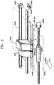
- Printing unit 250 has a line feed (LF) motor 250a which generates a rotating force used to feed document 200a or print media for printing out facsimile or print data thereon upon application of the control signal from print driver 240 or for feeding back test pattern 200a-1 to the scanning position after printing; an LF roller 250b which either feeds the print media or document 200a or feeds it back upon application of the rotating force from LF motor 250a; and a print head 250c that sprays ink particles for printing on the print media fed to LF roller 250b or for printing test pattern 200a-1 on document 200a.
- LF line feed
- Printing unit 250 also has shuttle scanner module 270 mounted on one side of print head 250c for scanning document 200a or test pattern 200a-1 printed on document 200a; a carriage return (CR) motor 250e providing the rotating force moving print head 250c or shuttle scanner module 270 to right or left in order to spray ink particles on document 200a or the print media; a time belt 250f transmitting the rotating force from CR motor 250e; a guide shaft 250d which guides print head 250c and shuttle scanner module 270 moved to right or left by time belt 250f; and a shuttle position sensor 250g that senses the position of shuttle scanner module 270.
- CR carriage return
- the following description relates to the deviation correcting program stored in system memory 220 of multi-tasking system 200.
- control sequence of deviation correction includes the steps of printing (S210) test pattern 200a-1 stored in system memory 220 (FIG. 2); once test pattern 200a-1 has been printed out, scanning (S220) test pattern 200a-1; calculating (S230) a deviation degree of scanned test pattern 200a-1; determining (S240) a direction in which test pattern 200a-1 is deviated; and correcting (S250) the scanning deviation in response to the result.
- Step S250 includes sub-steps of correcting (S250a) the left deviation if scanned test pattern 200a-1 is deviated to left during scanning in step S240; and correcting (S250b) the right deviation if scanned test pattern 200a-1 is deviated to right during scanning in step S240.
- PC 100 applies print data and facsimile data to CPU 230 through ECP 210 upon receipt of a facsimile signal sent from the outside, and ECP 210 is used as a parallel interface module for two-way communication.
- CPU 230 lets rasterizer 290 rasterize the applied facsimile date, and applies the rasterized data to print driver 240.
- the print data, applied to COU 230 of multi-tasking system 200, is also transmitted to print driver 240.
- Print driver 240 produces a print head fire/enable control signal, a CR motor phase/position control signal, or a print data handling/LF motor control signal upon application of the facsimile data or print data.
- Each control signal, output from print driver 240, is received from printing unit 250.
- Printing unit 250 feeds the print media with LF roller 250b, controlled by LF motor 250a, upon application of one of various control signals. Feeding the print media follows the printing operation with respect to data applied through print head 250c under the control of CR motor 250e and time belt 250f.
- Print head 250c sprays ink particles moving the print media, directed by a guide shaft 250d, to right or left, thus forming an image thereon corresponding to the facsimile data or print data.
- Document 200a is moved to an initial scanning position of shuttle scanner module 270 mounted on one side of print head 250d and using guide shaft 250d as a shaft for lateral shift.
- Shuttle scanner module 270 scans document 200a moved to its initial scanning position.
- a charge coupled device (CCD) used for shuttle scanner module 270 is of 128-dot size, and document 200a of A4 (2551 x 2507; 300 DPI) is divided into 27 blocks for scanning.
- CCD charge coupled device
- document 200a of A4 2551 x 2507; 300 DPI
- Shuttle scanner module 270's horizontal and vertical shifts are made by LF motor 250a and CR motor 250e.
- Shuttle scanner module 270 scans 27 blocks divided to scan A4 document 200a.
- the image data scanned by shuttle scanner module 270 is converted into digital data by ADC 260a of image processing unit 260.
- Image processing unit 260 corrects the image data in shading, gamma correction, dot per inch (DPI) conversion, edge emphasis, error diffusion, etc.
- the image data converted into digital data by image processing unit 260, is rasterized by rasterizer 290 and temporarily stored in image memory 280.
- Image memory 280 is used as a temporary buffer.
- the image data rasterized by rasterizer 290 and stored in image memory 280 is transmitted to print driver 240 or PC 100 through ECP 210 under the control of CPU 210.
- the data, sent to print driver 240, is re-printed out by printing portion 250, and if the date is transmitted to PC 100, it is stored through PC 100 or processed by a given program for storing.
- the data is shifted by the arrow indicative of an address and data bus, and shuttle scanner module 270 scans document 200a under the control of a clock CLK from image processing unit 260. If a signal is applied to CPU 230 through selection means (not shown) for checking or correcting shuttle scanner module 270's deviation according to a user's selecting one of the general functions of multi-tasking system 200, CPU 230 executes the deviation correcting program from system memory 220. According to this program, CPU 230 performs step S210 first. After loading test pattern 200a-1 from system memory 220, CPU 230 transmits that pattern to print driver 240 through ECP 210.
- Print driver 240 sends a print control signal to printing unit 250 upon application of test pattern 200a-1 from CPU 230.
- Printing unit 250 prints out test pattern 200a-1, as shown in FIG 3, by the use of ink particles from print head 250c upon receipt of the print control signal.
- shuttle scanner module scans documents 200a with printed test pattern 200a-1 through step S220. If completing the printing operation to scan document 200a with test pattern 200a-1, document 200a is fed back by LF roller 250b turned reversely by LF motor 250a. That is, test pattern 200a-1 of document 200a is fed back to the initial scanning position of shuttle scanner module 270, and scanned by shuttle scanner module 270.
- Test pattern 200a-1 scanned by shuttle scanner module 270 is converted into digital data, thus producing image data under the control of image processing unit 260.
- the image data is stored in image memory 280 through address and data bus under the control of image processing unit 260. If the image data is completely stored in image memory 280, CPU 230 executes step S230.
- step S230 an interval of adjacent dots in a predetermined spot of test pattern 200a-1 is calculated.
- a value of tilt is calculated from the interval of dots, and dot averages in the range of the calculated value of tilt are compared to compute a deviation degree of the scanned image data.
- CPU 230 determines if the scanned data is deviated to right or left in step S240. When the data is deviated to left, CPU 230 executes step S250a, thus correcting the image data's deviation to left during scanning. In addition, if CPU 230 determines (S240) that the scanned data is deviated to right, it executes step S250b, thus correcting the image data's deviation to right during scanning.
- the deviation correcting process in step S250 is carried out by clock CLK applied to shuttle scanner module 270, which is described in more detail with reference to the drawings.
- FIG. 5 depicts a process of correcting one-dot deviation between a first dot and a 128 th dot within a single slice ("a") of FIG.3).
- a single slice
- FIG. 5 depicts a process of correcting one-dot deviation between a first dot and a 128 th dot within a single slice ("a") of FIG.3).
- FIG. 5 when each of the first dot and the 128 th dot is divided into 32 dots and converted into 8-bit ADC 260a (FIG. 2), thus having 256 values.
- the state 256 values 16 is expressed in a hexadecimal number and divided into 00H to FFH.
- Step S230 includes the sub-steps of finding an average on the basis of the last dot in a second section 2 of quartered test pattern 200a-1 and calculating a deviation degree, finding an average on the basis of the last dot in a third section 3 of quartered test pattern 200-1 and calculating a deviation degree, finding an average on the basis of the last dot in a first section 1 of quartered test pattern 200a-1 and calculating a deviation degree; and finding an average on the basis of the last dot in a half part of first section 1 of quartered test pattern 200a-1 and calculating a deviation degree.
- an average of ⁇ 2 dot is obtained on the basis of a 64th dot, the last dot in second section 2,
- Test pattern 200a-1 is scanned through the steps, and a deviation value is calculated by using the scanned image data. If finding a deviation value through step S230 of scanned test pattern 200a-1, CPU 230 determines (step S240) if scanned test pattern 200a-1 is deviated to right or left.
- CPU 230 determines (step S240) that an average of 238 dots in test pattern 200a-1 equals FFH, it sets a reference value so as to determine that test pattern 200a-1 is deviated to right. If CPU 230 determines that it is deviated to left by using the reference value, it executes step S250a to correct the left deviation.
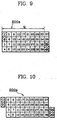
- CPU 230 determines (S230) that scanned test pattern 200a-1 is deviated to one-dot left, shaded data blocks 3, 4, 37 and 38 are moved to right for correction in order to scan data blocks 1 to 40 within a range of a length Q of a document 200a to be actually scanned (FIG 6). Shaded data blocks 3, 4, 37 and 38 are scanned to correct the deviation, as shown in FIG 7. If CPU 230 determines (S240) that scanned test pattern 200a-1 is deviated to right, it executes step S250b.
Landscapes
- Engineering & Computer Science (AREA)
- Multimedia (AREA)
- Signal Processing (AREA)
- Facsimile Scanning Arrangements (AREA)
- Accessory Devices And Overall Control Thereof (AREA)
- Ink Jet (AREA)
Applications Claiming Priority (4)
| Application Number | Priority Date | Filing Date | Title |
|---|---|---|---|
| KR19970019893 | 1997-05-22 | ||
| KR9719893 | 1997-05-22 | ||
| KR1019970070905A KR100328307B1 (ko) | 1997-05-22 | 1997-12-19 | 스케너의틀어짐보정장치및방법 |
| KR9770905 | 1997-12-19 |
Publications (2)
| Publication Number | Publication Date |
|---|---|
| EP0881819A2 true EP0881819A2 (de) | 1998-12-02 |
| EP0881819A3 EP0881819A3 (de) | 2000-11-15 |
Family
ID=26632752
Family Applications (1)
| Application Number | Title | Priority Date | Filing Date |
|---|---|---|---|
| EP98304115A Withdrawn EP0881819A3 (de) | 1997-05-22 | 1998-05-22 | Verschiebungskorrektursystem für Abtasten |
Country Status (3)
| Country | Link |
|---|---|
| US (1) | US6175428B1 (de) |
| EP (1) | EP0881819A3 (de) |
| JP (1) | JP2968520B2 (de) |
Cited By (4)
| Publication number | Priority date | Publication date | Assignee | Title |
|---|---|---|---|---|
| EP1011260A3 (de) * | 1997-12-08 | 2001-09-05 | Samsung Electronics Co., Ltd. | Abtastfehlerkorrektion in einem Pendelabtaster |
| WO2002091729A3 (en) * | 2001-05-03 | 2004-02-26 | Hewlett Packard Co | Apparatus and method for calibration of scan position for a peripheral device with document feeder |
| EP0883278B1 (de) * | 1997-06-03 | 2004-09-08 | Samsung Electronics Co., Ltd. | Positionskompensationsverfahren beim Zweirichtungsdruck und -Abtasten |
| EP1418745A3 (de) * | 2002-11-07 | 2005-10-12 | Xerox Corporation | System zur Kompensation der Nichtlinarität von Rasterzeilen zur Verwendung in einer Rasterabtastvorrichtung |
Families Citing this family (8)
| Publication number | Priority date | Publication date | Assignee | Title |
|---|---|---|---|---|
| US7387253B1 (en) * | 1996-09-03 | 2008-06-17 | Hand Held Products, Inc. | Optical reader system comprising local host processor and optical reader |
| US6643035B1 (en) * | 1999-11-24 | 2003-11-04 | Xerox Corporation | Method and apparatus for measuring scanner registration |
| US6967735B2 (en) * | 2001-04-06 | 2005-11-22 | Agfa Corporation | Enhanced networked pre-press imaging |
| KR100580183B1 (ko) * | 2004-01-09 | 2006-05-15 | 삼성전자주식회사 | 스캔영역의 좌우 위치 보정 방법 및 장치 |
| US7525702B2 (en) * | 2004-08-02 | 2009-04-28 | Seiko Epson Corporation | Methods and systems for correcting color distortions |
| US7949950B2 (en) * | 2005-04-22 | 2011-05-24 | Microsoft Corporation | Systems and methods for enhanced document composition features |
| US8154771B2 (en) * | 2008-01-29 | 2012-04-10 | K-Nfb Reading Technology, Inc. | Training a user on an accessiblity device |
| JP5283685B2 (ja) * | 2010-12-17 | 2013-09-04 | 富士フイルム株式会社 | 不良記録素子の検出装置及び方法、並びに画像形成装置及び方法 |
Family Cites Families (18)
| Publication number | Priority date | Publication date | Assignee | Title |
|---|---|---|---|---|
| US4135664A (en) * | 1977-03-04 | 1979-01-23 | Hurletronaltair, Inc. | Lateral register control system and method |
| DE2950650A1 (de) | 1979-12-15 | 1981-06-19 | M.A.N.- Roland Druckmaschinen AG, 6050 Offenbach | Vorrichtung zur opto- elektronischen messung der flaechendeckung einer offset-druckplatte oder einer der offset-druckplattenherstellung dienenden druckvorlage |
| EP0257570A3 (de) * | 1986-08-25 | 1988-11-30 | Siemens Aktiengesellschaft | Verfahren zum Abgleich der Schreibdüsen eines Tintendruckkopfes in Tintenschreibeinrichtungen und Schaltungsanordnung zur Durchührung des Verfahrens |
| NL8603173A (nl) * | 1986-12-12 | 1988-07-01 | Daisy Syst Holland | Tekstverwerkingssysteem, alsmede afdrukeenheid voor een dergelijk tekstverwerkingssysteem. |
| JPS63169871A (ja) * | 1987-01-08 | 1988-07-13 | Dainippon Screen Mfg Co Ltd | 副走査方向読取り位置ずれ補正方法 |
| US5011413A (en) | 1989-07-19 | 1991-04-30 | Educational Testing Service | Machine-interpretable figural response testing |
| US5410620A (en) | 1989-08-02 | 1995-04-25 | Teiryo Sangyo Co., Ltd. | Digital data reader of digital data recording sheet |
| US5144448A (en) * | 1990-07-31 | 1992-09-01 | Vidar Systems Corporation | Scanning apparatus using multiple CCD arrays and related method |
| US5231663A (en) | 1991-03-18 | 1993-07-27 | Earl Joseph G | Image processing system |
| JP2567276Y2 (ja) | 1991-06-19 | 1998-04-02 | 旭光学工業株式会社 | 電子写真プリンタの試験装置 |
| US5715105A (en) | 1992-09-28 | 1998-02-03 | Hitachi, Ltd. | Method of and apparatus for recording on and reproducing from disk-type recording medium having recording tracks with sectors each having an ID area and a data area |
| JP3157063B2 (ja) * | 1993-05-19 | 2001-04-16 | 株式会社リコー | カラー画像入力装置 |
| US5546165A (en) | 1994-10-05 | 1996-08-13 | Eastman Kodak Company | Scanner as test print densitometer for compensating overall process drift and nonuniformity |
| US5642202A (en) * | 1994-12-01 | 1997-06-24 | Xerox Corporation | Scan image target locator system for calibrating a printing system |
| JP3461402B2 (ja) * | 1995-02-28 | 2003-10-27 | 株式会社リコー | ファクシミリ装置 |
| US5745658A (en) | 1995-11-16 | 1998-04-28 | Datastrip Products Inc. | Method of aligning one dimensional or two dimensional codes to printer pixels |
| US5978506A (en) * | 1995-12-28 | 1999-11-02 | Ricoh & Company, Ltd. | Colorant-independent color balancing methods and systems |
| US5706409A (en) | 1996-07-01 | 1998-01-06 | Xerox Corporation | Image shifting system for use in a document processing system |
-
1998
- 1998-05-22 EP EP98304115A patent/EP0881819A3/de not_active Withdrawn
- 1998-05-22 JP JP10141898A patent/JP2968520B2/ja not_active Expired - Fee Related
- 1998-05-22 US US09/083,080 patent/US6175428B1/en not_active Expired - Fee Related
Cited By (7)
| Publication number | Priority date | Publication date | Assignee | Title |
|---|---|---|---|---|
| EP0883278B1 (de) * | 1997-06-03 | 2004-09-08 | Samsung Electronics Co., Ltd. | Positionskompensationsverfahren beim Zweirichtungsdruck und -Abtasten |
| EP1011260A3 (de) * | 1997-12-08 | 2001-09-05 | Samsung Electronics Co., Ltd. | Abtastfehlerkorrektion in einem Pendelabtaster |
| EP1583344A3 (de) * | 1997-12-08 | 2005-11-30 | Samsung Electronics Co., Ltd. | Abtastfehlerkorrektion in einem Pendelabtaster |
| EP1583345A3 (de) * | 1997-12-08 | 2005-11-30 | Samsung Electronics Co., Ltd. | Bildfehlerkorrektur in Pendelabtaster |
| WO2002091729A3 (en) * | 2001-05-03 | 2004-02-26 | Hewlett Packard Co | Apparatus and method for calibration of scan position for a peripheral device with document feeder |
| US6813573B2 (en) | 2001-05-03 | 2004-11-02 | Hewlett-Packard Development Company, L.P. | Apparatus and method for calibration of scan position for a peripheral device with document feeder |
| EP1418745A3 (de) * | 2002-11-07 | 2005-10-12 | Xerox Corporation | System zur Kompensation der Nichtlinarität von Rasterzeilen zur Verwendung in einer Rasterabtastvorrichtung |
Also Published As
| Publication number | Publication date |
|---|---|
| US6175428B1 (en) | 2001-01-16 |
| EP0881819A3 (de) | 2000-11-15 |
| JP2968520B2 (ja) | 1999-10-25 |
| JPH1127483A (ja) | 1999-01-29 |
Similar Documents
| Publication | Publication Date | Title |
|---|---|---|
| US7494204B2 (en) | Correction of paper feed error during interlace printing using a representative correction value | |
| JP5139876B2 (ja) | 画像形成装置及び画像形成方法 | |
| US7874634B2 (en) | Image forming apparatus and image forming method | |
| EP0881819A2 (de) | Verschiebungskorrektursystem für Abtasten | |
| JPH1120238A (ja) | ドット記録方法および装置、並びに、そのためのプログラムを記録した記録媒体 | |
| US8976416B2 (en) | Image processing apparatus and method thereof | |
| US6467866B1 (en) | Print control method and apparatus, and printing apparatus using the same | |
| JP2011259121A (ja) | 画像処理装置及びプログラム | |
| US8289571B2 (en) | Bidirectional multi-pass inkjet printer suppressing density unevenness based on interval between scans | |
| US6497467B2 (en) | Inkjet printer, and method and apparatus for controlling inkjet printer | |
| US6353481B1 (en) | Technique for correcting printing errors in a shuttle type multifunctional apparatus | |
| EP0883278A2 (de) | Positionskompensationsverfahren beim Zweirichtungsdruck und -Abtasten | |
| JP5682126B2 (ja) | 印刷装置、印刷方法およびプログラム | |
| JPH1199638A (ja) | インクジェット画像記録方法及び装置 | |
| JP2010120267A (ja) | 印刷制御装置および印刷装置 | |
| JP3397059B2 (ja) | 印刷装置および画像記録方法 | |
| US6147766A (en) | Printing apparatus for increasing efficiency in transmitting image data between internal control units | |
| JP2004216615A (ja) | 印刷装置、プログラム及びコンピュータシステム | |
| US6115130A (en) | Method of recognizing printing region | |
| JP5343504B2 (ja) | インクジェット記録装置、画像形成システム、画像形成方法、及びプログラム | |
| US6024437A (en) | Method and apparatus for recording color images in both interlaced and non-interlaced modes | |
| JP2003231246A (ja) | プリンタにおける紙送り誤差の補正 | |
| JPH05305733A (ja) | 画像記録方法及び装置 | |
| JP2023115489A (ja) | 記録装置および記録方法 | |
| EP0917094B1 (de) | Druckersteuerungssystem und -Verfahren |
Legal Events
| Date | Code | Title | Description |
|---|---|---|---|
| PUAI | Public reference made under article 153(3) epc to a published international application that has entered the european phase |
Free format text: ORIGINAL CODE: 0009012 |
|
| 17P | Request for examination filed |
Effective date: 19980522 |
|
| AK | Designated contracting states |
Kind code of ref document: A2 Designated state(s): DE FR GB IT |
|
| AX | Request for extension of the european patent |
Free format text: AL;LT;LV;MK;RO;SI |
|
| PUAL | Search report despatched |
Free format text: ORIGINAL CODE: 0009013 |
|
| AK | Designated contracting states |
Kind code of ref document: A3 Designated state(s): AT BE CH CY DE DK ES FI FR GB GR IE IT LI LU MC NL PT SE |
|
| AX | Request for extension of the european patent |
Free format text: AL;LT;LV;MK;RO;SI |
|
| AKX | Designation fees paid |
Free format text: DE FR GB IT |
|
| 17Q | First examination report despatched |
Effective date: 20011109 |
|
| STAA | Information on the status of an ep patent application or granted ep patent |
Free format text: STATUS: THE APPLICATION IS DEEMED TO BE WITHDRAWN |
|
| 18D | Application deemed to be withdrawn |
Effective date: 20030819 |