EP0882539A2 - Appareil de jonction par diffusion pour tubes - Google Patents
Appareil de jonction par diffusion pour tubes Download PDFInfo
- Publication number
- EP0882539A2 EP0882539A2 EP98106407A EP98106407A EP0882539A2 EP 0882539 A2 EP0882539 A2 EP 0882539A2 EP 98106407 A EP98106407 A EP 98106407A EP 98106407 A EP98106407 A EP 98106407A EP 0882539 A2 EP0882539 A2 EP 0882539A2
- Authority
- EP
- European Patent Office
- Prior art keywords
- pipes
- pipe
- diffusion bonding
- bonding apparatus
- upper pipe
- Prior art date
- Legal status (The legal status is an assumption and is not a legal conclusion. Google has not performed a legal analysis and makes no representation as to the accuracy of the status listed.)
- Withdrawn
Links
- 238000009792 diffusion process Methods 0.000 title claims abstract description 46
- 238000003825 pressing Methods 0.000 claims abstract description 31
- 230000007246 mechanism Effects 0.000 claims description 52
- 210000000078 claw Anatomy 0.000 claims description 22
- 238000010438 heat treatment Methods 0.000 description 11
- 230000006698 induction Effects 0.000 description 10
- 230000005540 biological transmission Effects 0.000 description 3
- 238000000034 method Methods 0.000 description 3
- 239000003129 oil well Substances 0.000 description 3
- 230000000694 effects Effects 0.000 description 2
- 238000003780 insertion Methods 0.000 description 2
- 230000037431 insertion Effects 0.000 description 2
- 238000007689 inspection Methods 0.000 description 2
- 238000005520 cutting process Methods 0.000 description 1
- 238000012840 feeding operation Methods 0.000 description 1
- 239000000945 filler Substances 0.000 description 1
- 238000004519 manufacturing process Methods 0.000 description 1
Images


Classifications
-
- B—PERFORMING OPERATIONS; TRANSPORTING
- B23—MACHINE TOOLS; METAL-WORKING NOT OTHERWISE PROVIDED FOR
- B23K—SOLDERING OR UNSOLDERING; WELDING; CLADDING OR PLATING BY SOLDERING OR WELDING; CUTTING BY APPLYING HEAT LOCALLY, e.g. FLAME CUTTING; WORKING BY LASER BEAM
- B23K20/00—Non-electric welding by applying impact or other pressure, with or without the application of heat, e.g. cladding or plating
- B23K20/26—Auxiliary equipment
-
- B—PERFORMING OPERATIONS; TRANSPORTING
- B23—MACHINE TOOLS; METAL-WORKING NOT OTHERWISE PROVIDED FOR
- B23K—SOLDERING OR UNSOLDERING; WELDING; CLADDING OR PLATING BY SOLDERING OR WELDING; CUTTING BY APPLYING HEAT LOCALLY, e.g. FLAME CUTTING; WORKING BY LASER BEAM
- B23K20/00—Non-electric welding by applying impact or other pressure, with or without the application of heat, e.g. cladding or plating
- B23K20/02—Non-electric welding by applying impact or other pressure, with or without the application of heat, e.g. cladding or plating by means of a press ; Diffusion bonding
- B23K20/028—Butt welding
-
- B—PERFORMING OPERATIONS; TRANSPORTING
- B23—MACHINE TOOLS; METAL-WORKING NOT OTHERWISE PROVIDED FOR
- B23K—SOLDERING OR UNSOLDERING; WELDING; CLADDING OR PLATING BY SOLDERING OR WELDING; CUTTING BY APPLYING HEAT LOCALLY, e.g. FLAME CUTTING; WORKING BY LASER BEAM
- B23K37/00—Auxiliary devices or processes, not specially adapted for a procedure covered by only one of the other main groups of this subclass
- B23K37/04—Auxiliary devices or processes, not specially adapted for a procedure covered by only one of the other main groups of this subclass for holding or positioning work
- B23K37/053—Auxiliary devices or processes, not specially adapted for a procedure covered by only one of the other main groups of this subclass for holding or positioning work aligning cylindrical work; Clamping devices therefor
- B23K37/0533—External pipe alignment clamps
-
- Y—GENERAL TAGGING OF NEW TECHNOLOGICAL DEVELOPMENTS; GENERAL TAGGING OF CROSS-SECTIONAL TECHNOLOGIES SPANNING OVER SEVERAL SECTIONS OF THE IPC; TECHNICAL SUBJECTS COVERED BY FORMER USPC CROSS-REFERENCE ART COLLECTIONS [XRACs] AND DIGESTS
- Y10—TECHNICAL SUBJECTS COVERED BY FORMER USPC
- Y10T—TECHNICAL SUBJECTS COVERED BY FORMER US CLASSIFICATION
- Y10T279/00—Chucks or sockets
- Y10T279/12—Chucks or sockets with fluid-pressure actuator
- Y10T279/1274—Radially reciprocating jaws
- Y10T279/1291—Fluid pressure moves jaws via mechanical connection
-
- Y—GENERAL TAGGING OF NEW TECHNOLOGICAL DEVELOPMENTS; GENERAL TAGGING OF CROSS-SECTIONAL TECHNOLOGIES SPANNING OVER SEVERAL SECTIONS OF THE IPC; TECHNICAL SUBJECTS COVERED BY FORMER USPC CROSS-REFERENCE ART COLLECTIONS [XRACs] AND DIGESTS
- Y10—TECHNICAL SUBJECTS COVERED BY FORMER USPC
- Y10T—TECHNICAL SUBJECTS COVERED BY FORMER US CLASSIFICATION
- Y10T279/00—Chucks or sockets
- Y10T279/18—Pivoted jaw
Definitions
- the present invention relates to a diffusion bonding apparatus for pipes, more particularly a diffusion bonding apparatus for pipes capable of diffusion bonding a pipe that is supplied from above with a pipe that is placed in position therebelow by evenly pressing them against each other.
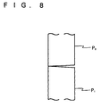
- an apparatus A' for achieving diffusion bonding by vertically holding a pipe (lower pipe) P1 to be bonded, supplying the other pipe (upper pipe) P2 to be bonded therewith downward from above in the vertical direction, allowing an end surface of the upper pipe P2 to be pressed against an end surface of the lower pipe P1 that is held vertically therebelow, then heating the relevant joint for diffusion bonding them, it is considered that such pipe as an oil well pipe extending as far as several kilometers after bonding can be produced.
- An apparatus of above constitution is herein referred to as a vertical diffusion bonding apparatus A'.
- the invention has been achieved in view of such problems of the prior art, and it is an object of the invention to provide a diffusion bonding apparatus for pipes capable of achieving diffusion bonding by evenly pressing pipes against each other even when the perpendicularity of end surfaces of the pipes to be bonded with respect to a longitudinal center thereof is somehow low in accuracy.
- a diffusion bonding apparatus for pipes allows pipes to be supplied downward from above, and comprises a lower block for holding a lower pipe and an upper block for holding and pressing an upper pipe against the lower pipe, wherein three or more hydraulic cylinders are provided in a lifting member of the upper block about a position where the upper pipe is held in such manner that the cylinders are located in a circumference of a circle.
- a diffusion bonding apparatus for pipes of the invention it is preferable that three of said hydraulic cylinders are provided, and an angle between the hydraulic cylinders is set within a range of 110 degree to 130 degree with respect to a point of center.
- the upper block comprises horizontal position adjusting means for adjusting a position of the upper pipe that is held by the upper block in a horizontal surface.
- the upper block comprises inclination adjusting means for adjusting inclination of the upper pipe.
- the lifting member comprises an outer element and an inner element for holding the upper pipe, held in an inner side of the outer element in such manner that it can be horizontally moved and adjusted in inclination.
- the horizontal position adjusting means comprises, for example, a horizontally moving member for holding the inner element, held in an inner side of the outer element in such manner that it can be horizontally moved, a first driving screw member provided for spirally moving inward and outward the outer element and a second driving screw member provided at an angle of 90 degree to the first driving screw member for spirally moving inward and outward with respect to the outer element, and a horizontal position of the inner element is adjusted by adjusting a driving amount of the horizontally moving member by means of the first driving screw member and or second driving screw member so that a horizontal position of the upper pipe is thereby adjusted.
- the inclination adjusting means comprises, for example, a cylindrical member rotatably held by the horizontally moving member for supporting flange elements that are provided in an outer circumference of the inner element, disc cam members provided concentrically at an angle of 120 degree to the cylindrical member for supporting the flange elements that are provided in the outer circumference of the inner element and a driving mechanism for driving the disc cam members, and a height of the disc cam members supporting the flange elements is adjusted by means of the driving mechanism so that inclination of the upper pipe that is held by the inner element is thereby adjusted.
- the inner element comprises, for example, upper clamp means provided in an upper part thereof and lower clamp means provided in an lower part thereof, so that the upper pipe is clamped by the upper clamp means at a desired clamping force, and deformation of a bonded surface of the upper pipe is prevented by the lower clamp means.
- a distance between the upper clamp means and lower clamp means is three times or more of a diameter of the upper pipe that is clamped, and the upper clamp means and lower clamp means preferably comprise first, second and third claw blocks that are provided at an angle of 120 degree to each other.
- a bonding apparatus for pipes according to the invention is constituted as described above, an upper pipe is bonded with a lower pipe while they are evenly pressed against each other. As a result, a quality of bonded joint and a bonding strength are increased.
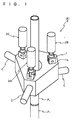
- FIG. 1 An embodiment of a pressing device F employed in a vertical bonding apparatus of the invention is shown in a conceptual view in Fig. 1.
- the pressing device F is employed in a vertical diffusion bonding apparatus for diffusion bonding pipes P.
- the pressing device F consists of three sets of hydraulic cylinders 2, that is, a first hydraulic cylinder 2A, a second hydraulic cylinder 2B and a third hydraulic cylinder 2C provided in an upper surface 1a of a lifting member 1 that incorporates clamp means (not clearly shown) for clamping an upper pipe P2 in an upper mechanism (not shown) for supplying vertically from above the pipe (upper pipe) P2 to be bonded with a pipe (lower pipe) P1 that is held and placed in position by a lower mechanism (not shown) of the vertical diffusion bonding apparatus at a same distance from a center of the lifting member about which the upper pipe P2 is clamped and an angle of 120 degree from each other.
- a reference symbol C shows a driving cylinder of the clamp means.
- the end surface of upper pipe P2 can be evenly pressed against the end surface of lower pipe P1 by such simple operation of using a same hydraulic pressure for the hydraulic cylinders 2.
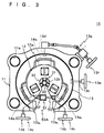
- Fig. 2 a schematic view of a diffusion bonding apparatus with the pressing device F is shown, where the diffusion bonding apparatus is so-called vertical diffusion bonding apparatus A for vertically supplying pipes P to be bonded from above, and diffusion bonding them, and mainly comprises an upper block U vertically movable for supplying the pipes P and a lower block L for holding the lower pipe P1 that is bonded with the upper pipe P2 supplied by the upper block U.
- vertical diffusion bonding apparatus A for vertically supplying pipes P to be bonded from above, and diffusion bonding them, and mainly comprises an upper block U vertically movable for supplying the pipes P and a lower block L for holding the lower pipe P1 that is bonded with the upper pipe P2 supplied by the upper block U.
- the upper block U mainly comprises a main body (lifting member) 10 of the upper block, a lifting and pressing mechanism 20 for lifting and pressing the main body 10, a first clamping mechanism (upper clamping mechanism) 30 provided in an upper part of the main body 10 and a second clamping mechanism (lower clamping mechanism) 40 provided in a lower part of the main body 10.
- the lifting and pressing mechanism 20 mainly comprises, in detail, four cylindrical guide posts 21 arranged in a rectangular shape on a base B, four main beams 22 arranged in a rectangular shape over top parts of the guide posts 21, the pressing device F with three sets of hydraulic cylinders 23, that is, the first hydraulic cylinder 23A, second hydraulic cylinder 23B and third hydraulic cylinder 23C provided concentrically at an angle of 120 degree from each other and support beams (not clearly shown) connected in an appropriate arrangement with the main beams 22 for supporting the hydraulic cylinders 23A, 23B and 23C of the pressing device F downward through support members 24.
- three sets of hydraulic cylinders 23 at a regular interval, three-point pressing is achieved, and a pressure can be evenly distributed in a circumference of an end surface of the pipe P to be bonded, as described above.
- the main body (lifting member) 10 of the upper block mainly comprises an outer element 11 and an inner element 12 with a main part thereof provided inside the outer element 11, and incorporates a horizontal position adjusting mechanism 13 for adjusting a horizontal position of the inner element 12 and an inclination adjusting mechanism 14 for adjusting inclination of the inner element 12.
- the outer element 11 is in the shape of a rectangular parallelepiped with a hollow area for housing the inner element 12 provided in the inside and a lengthwise surface cut off through a specified width.
- guide post through holes 11a for slidably attaching the guide posts 21 to the outer element 11 are formed.
- An upper end 11b and a lower end 11c of the guide post receiver 11a are projected to a specified height from upper and lower surfaces of the rectangular parallelepiped that constitutes the outer element 11, and an outer circumference thereof is also projected in an arcuate shape from a corner of the rectangular parallelepiped (see Fig. 3).
- an inner surface of the rectangular parallelepiped constituting the outer element 11 is cut off to a specified depth through a specified width, and a groove-like cavity 11d is formed in the inner surface thereof.
- a horizontally moving member 13a of the horizontal position adjusting mechanism 13 is provided in the groove-like cavity 11d, and multiple bearing balls 13b are placed in a space between upper and lower surfaces of the horizontally moving member 13a and upper and bottom surfaces of the groove-like cavity 11d in the outer element 11 through an entire circumference thereof in order to allow horizontal movement of the horizontally moving member 13a.
- the upper and lower surfaces of horizontally moving member 13a is provided with a concave joint of an appropriate depth in an area where the bearing balls 13b are placed.
- the upper and bottom surfaces of the groove-like cavity 11d in the outer element 11 may be also provided with a concave joint of such width that assures horizontal movement of the horizontally moving member 13a in an area where the bearing balls 13b are placed.
- a part formed with the concave joint of an upper part of the outer element 11 is formed as a lid 11e for removability. Because of such constitution of the outer element 11, placement of the bearing balls 13b and attachment of the horizontally moving member 13a is facilitated.
- the horizontally moving member 13a is horizontally moved by means of driving screw members 13c and 13d that are, provided in appropriate positions in widthwise and lengthwise sides of the outer element 11, respectively, as shown in Figs. 2 to 3 and 6, and physically connected at an end thereof with the horizontally moving member 13a (see Fig. 6).
- driving screw members 13c and 13d that are, provided in appropriate positions in widthwise and lengthwise sides of the outer element 11, respectively, as shown in Figs. 2 to 3 and 6, and physically connected at an end thereof with the horizontally moving member 13a (see Fig. 6).
- the handle 13f of driving screw member (Y-axis driving screw member) 13d provided in the lengthwise side is located in the vicinity of the handle 13e of driving screw member (X-axis driving screw member) 13c provided in the widthwise side, and the driving screw member 13d is adapted to be rotated by a driving force transmission mechanism 13g.
- a groove-like cavity 13h is provided in an inner surface of a lower part of the horizontally moving element 13a. Then, in an upper part of the groove-like cavity 13h, three flange elements 12a formed in a side of the inner element 12 are provided with a specified spacing from the upper surface of groove-like cavity 13h. These three flange elements 12a are a first flange element 12a1 formed in consistency with the direction of Y-axis, and a second flange element 12a2 and a third flange element 12a3 formed at an angle of 120 degree from the first flange element 12a1 respectively.
- a first inclination adjusting member 14a1, a second inclination adjusting member 14a2 and a third inclination adjusting member 14a3 of the inclination adjusting mechanism 14 are provided in contact with a lower surface of the flange members 12a1, 12a2 and 12a3.
- the second and third inclination adjusting members 14a2 and 14a3 are disc cams. By rotating the disc cams to a specified extent in the specified direction through driving force transmission mechanisms 14b, an angle of inclination of the inner element 12 is adjusted (see Fig. 6).
- Handles 14c of the driving force transmission mechanisms 14b are provided in a same lengthwise side for operating convenience thereof (see Fig. 3).
- the inner element 12 is cut out in a sectoral shape in a part corresponding to the cut-out joint of the outer element 11, is in the shape of a hollow cylinder with a circular through-hole 12b provided in the upper and lower surfaces for insertion of the upper pipe P2, and is formed in a side thereof with the first, second and third flange elements 12a1, 12a2 and 12a3 in positions corresponding to the groove-like cavities 13h of the horizontally moving member 13a, as described above.
- three connecting members 12c connected with front ends of piston rods 24 of the hydraulic cylinders 23 in the lifting and pressing mechanism 20 are concentrically provided at a regular interval.
- These three connecting members 12c are a first connecting member 12c1 provided in consistency with the direction of Y-axis and a second connecting member 12c2 and a third connecting member 12c3 provided at an angle of 120 degree from the first connecting member 12c1, respectively.
- the first clamping mechanism 30 serves for clamping the upper pipe P2 in such manner that a specified clamping force can be obtained during diffusion bonding, and comprises, in detail, a first clamping claw 31 provided in consistency with the direction of Y-axis, movable together with the inner element 12 and capable of being advanced and retracted with respect to the upper pipe P2 and a second clamping claw 32 and a third clamping claw 33 provided, respectively, at an angle of 120 degree from the first clamping claw 31, also movable together with the inner element 12 and capable of being advanced and retracted with respect to the upper pipe P2.
- first, second and third clamping claws 31, 32 and 33 Advancing and retracting movement of the first, second and third clamping claws 31, 32 and 33 is achieved, for example, as they are driven by the hydraulic cylinders 34 (see Fig. 2).
- first, second and third clamping claws 31, 32 and 33 are driven by the hydraulic cylinders, for allowing projection of the hydraulic cylinders 12 beyond the outer circumference of inner element 12, cavities 13i for accommodating the hydraulic cylinders are provided in the horizontally moving member 13a in correspondence with the hydraulic cylinders 34 (see Fig. 2).
- the second clamping mechanism 40 is for preventing deformation of an end to be bonded of the upper pipe P2, and comprises, similarly to the first clamping mechanism 30, a first clamping claw provided in consistency with the direction of Y-axis, movable together with the inner element and capable of being advanced and retracted and a second clamping claw 42 and a third clamping claw 43 provided, respectively, at an angle of 120 degree from the first clamping claw, also movable together with the inner element 12 and capable of being advanced and retracted.
- positions of attachment of the first clamping claw, second clamping claw 42 and third clamping claw 43 to the inner element 12 is adjusted such that hydraulic cylinders 44 for driving the first clamping claw, second clamping claw 42 and third clamping claw 43 is located below the bottom surface of rectangular parallelepiped constituting the outer element 11.
- a spacing between the first clamping mechanism 32 and second clamping mechanism 40 is set at three times or more, preferably five times or more of the diameter of upper pipe P2. By providing such spacing, a clamping force of the first clamping mechanism 30 has almost no effect on deformation the end surface of upper pipe P2.
- a deformation preventing mechanism 50A is provided at two, upper and lower, locations in a side of the cut-out joint for preventing the cut-out joint from being enlarged by a reactive force when the upper pipe P2 is clamped by the first and second clamping mechanisms 30 and 40.
- the deformation preventing mechanism 50A practically consists of a hydraulic cylinder 51, and a base 52 of the hydraulic cylinder 51 is pivotally attached to an end of the cut-out joint, while a leading end of piston rod 53 thereof is secured to the other end so that deformation the inner element 12 as it is clamped by the first and second clamping mechanisms 30 and 40 is prevented by a tensile force thereof.
- the lower block L mainly comprises a main body 60 of the lower block, a third clamping mechanism 70 provided in an upper part of the main body 60, an induction heating device 80 placed above the main body 60 and an end surface finishing device 90 positioned in a side of the main body 60.
- the end surface finishing device 90 is also applicable to the pipe P with an unfinished end surface, it is mainly used for repairing such damage as nick caused in an end surface of the pipe P that is supplied after the end surface is finished.
- the main body 60 of lower block consists of a hat-shaped member 61 with a through-hole 62 provided in a central joint of upper surface thereof for allowing insertion of the pipe P, and a flange 63 of the main body is placed on a lower clamping device G for clamping the lower pipe P1, and fixed thereto.
- the hat-shaped member 61 is formed with a cut-out joint similar to the cut-out joint in the inner element 12 of the main body 60 of upper block at a location corresponding thereto and a deformation preventing mechanism 50B constituted similarly to the deformation preventing mechanism 50A in an upper part thereof for preventing deformation of the main body 60 when the lower pipe P1 is clamped by the third clamping mechanism 70.
- the third clamping mechanism 70 comprises a first clamping claw 71 provided in consistency with the direction of Y-axis and capable of being advanced and retracted with respect to the lower pipe P1 and a second clamping claw 72 and a third clamping claw 73 provided, respectively at an angle of 120 degree from the first clamping claw 71 and capable of being advanced and retracted with respect to the lower pipe P1.
- the induction heating device 80 mainly comprises two halves of induction heating coils 81 and 82, and the halves of induction heating coils 81 and 82 are placed in opposition to each other, and held by a holding member 64 employed in an upper surface of the main body 60.
- the induction heating coils 81, 82 are movable toward and away from the pipe P. Constitution of the induction heating device 80 with two halves of induction heating coils 81 and 82 is disclosed in the prior application (Japanese Patent Application No. 9-74582) of the applicant.
- the end surface finishing device 90 comprises, as shown in Figs. 4 and 5, a rail 91 of a specified length placed toward the pipe P on the lower clamping device C and fixed thereto, a radial carriage 92 movable along the rail 91, a transverse carriage 93 provided in the radial carriage 92 and movable transversely to the moving direction of the radial carriage 92, a lifting member 94 located in a front part of the transverse carriage 93 for vertical movement and an end surface finishing mechanism 95 projected forward from the lifting member 94.
- the end surface finishing device 95 mainly comprises, as shown in Fig. 5, a rotary-type finishing tool 96 with cutting blades 97 provided at upper and lower ends thereof, a motor 98 for rotating the rotary-type finishing tool 96 and torque transmitting means (not clearly shown) consisting of a timing belt and the like that transmit a torque of the motor 98 to the rotary-type finishing tool 96.
- the invention has been described by referring to an embodiment above, the invention is not limited to the embodiment, and can be modified in various manners.
- three sets of hydraulic cylinders are placed at a regular interval of an angle of 120 degree, they may not be positioned exactly at a regular interval of 120 degree, and the spacing between them may slightly vary.
- they may be placed at an appropriate angle within a range of 110 degree to 130 degree from each other.
- a spacing between the first and second hydraulic cylinders may be 110 degree
- a spacing between the second and third hydraulic cylinders may be 130 degree
- a spacing between the third and first hydraulic cylinders may be 120 degree.
- Provision of three sets of hydraulic cylinders is not restrictive, and four or five sets of hydraulic cylinders may be provided.
- the end surface of upper pipe can be more evenly pressed against the end surface of lower pipe as more hydraulic cylinders are provided, it is not preferable to employ too many hydraulic cylinders, because increase in the number of hydraulic cylinders results in a more complicated structure.
- a vertical diffusion bonding apparatus is provided as a bonding apparatus, the invention is not limited to a vertical diffusion bonding apparatus, can be applied to a lateral diffusion bonding apparatus, is not limited to a diffusion bonding apparatus either, and can be applied to various bonding apparatuses.
Landscapes
- Engineering & Computer Science (AREA)
- Mechanical Engineering (AREA)
- Physics & Mathematics (AREA)
- Optics & Photonics (AREA)
- Pressure Welding/Diffusion-Bonding (AREA)
Applications Claiming Priority (6)
| Application Number | Priority Date | Filing Date | Title |
|---|---|---|---|
| JP165076/97 | 1997-06-06 | ||
| JP16507697A JPH11771A (ja) | 1997-06-06 | 1997-06-06 | 接合装置 |
| JP31626397 | 1997-10-31 | ||
| JP316263/97 | 1997-10-31 | ||
| JP60524/98 | 1998-02-24 | ||
| JP6052498A JPH11192563A (ja) | 1997-10-31 | 1998-02-24 | 配管材の拡散接合装置 |
Publications (1)
| Publication Number | Publication Date |
|---|---|
| EP0882539A2 true EP0882539A2 (fr) | 1998-12-09 |
Family
ID=27297224
Family Applications (1)
| Application Number | Title | Priority Date | Filing Date |
|---|---|---|---|
| EP98106407A Withdrawn EP0882539A2 (fr) | 1997-06-06 | 1998-04-07 | Appareil de jonction par diffusion pour tubes |
Country Status (4)
| Country | Link |
|---|---|
| US (1) | US6098866A (fr) |
| EP (1) | EP0882539A2 (fr) |
| CA (1) | CA2234596C (fr) |
| NO (1) | NO981936L (fr) |
Cited By (2)
| Publication number | Priority date | Publication date | Assignee | Title |
|---|---|---|---|---|
| US6184493B1 (en) | 1998-08-19 | 2001-02-06 | Daido Tokushuko Kabushiki Kaisha | Vertical diffusion bonding apparatus |
| CN111468847A (zh) * | 2020-05-22 | 2020-07-31 | 昆山允可精密工业技术有限公司 | 一种管材、棒料气动夹持装置 |
Families Citing this family (20)
| Publication number | Priority date | Publication date | Assignee | Title |
|---|---|---|---|---|
| CN100411819C (zh) * | 2005-12-23 | 2008-08-20 | 昆山市华恒焊接设备技术有限责任公司 | 柔性自动定心夹具 |
| US8123104B1 (en) * | 2010-04-06 | 2012-02-28 | United Launch Alliance, Llc | Friction welding apparatus, system and method |
| US8141764B1 (en) | 2010-04-06 | 2012-03-27 | United Launch Alliance, Llc | Friction stir welding apparatus, system and method |
| US7866532B1 (en) | 2010-04-06 | 2011-01-11 | United Launch Alliance, Llc | Friction stir welding apparatus, system and method |
| DE102012109782A1 (de) * | 2012-10-15 | 2014-04-17 | Karlsruher Institut für Technologie | Schichtverbund |
| US10695876B2 (en) | 2013-05-23 | 2020-06-30 | Crc-Evans Pipeline International, Inc. | Self-powered welding systems and methods |
| US10589371B2 (en) | 2013-05-23 | 2020-03-17 | Crc-Evans Pipeline International, Inc. | Rotating welding system and methods |
| US11767934B2 (en) | 2013-05-23 | 2023-09-26 | Crc-Evans Pipeline International, Inc. | Internally welded pipes |
| US10040141B2 (en) | 2013-05-23 | 2018-08-07 | Crc-Evans Pipeline International, Inc. | Laser controlled internal welding machine for a pipeline |
| US9821415B2 (en) | 2014-03-28 | 2017-11-21 | Crc-Evans Pipeline International, Inc. | Internal pipeline cooler |
| US10480862B2 (en) | 2013-05-23 | 2019-11-19 | Crc-Evans Pipeline International, Inc. | Systems and methods for use in welding pipe segments of a pipeline |
| EP4230337A3 (fr) | 2013-12-18 | 2023-11-15 | Aster Co., Ltd. | Appareil de fabrication d'une bobine et procédé de fabrication d'une bobine |
| JP5592554B1 (ja) | 2013-12-18 | 2014-09-17 | 武延 本郷 | 冷間圧接装置、コイル製造装置、コイルおよびその製造方法 |
| CN104191059B (zh) * | 2014-08-29 | 2016-01-20 | 中核(天津)机械有限公司 | 一种异型管件焊接设备 |
| AU2015308646A1 (en) | 2014-08-29 | 2017-02-09 | Crc-Evans Pipeline International Inc. | Method and system for welding |
| DE202014105432U1 (de) * | 2014-11-12 | 2016-01-25 | Kuka Systems Gmbh | Pressschweißvorrichtung |
| US10260291B2 (en) * | 2016-04-27 | 2019-04-16 | Broco, Inc. | Portable drill pipe hard banding machine |
| US11458571B2 (en) | 2016-07-01 | 2022-10-04 | Crc-Evans Pipeline International, Inc. | Systems and methods for use in welding pipe segments of a pipeline |
| US10668577B2 (en) | 2016-09-01 | 2020-06-02 | Crc-Evans Pipeline International Inc. | Cooling ring |
| FR3092155B1 (fr) * | 2019-01-30 | 2021-01-29 | Saipem Sa | Dispositif et procédé de mise à joint d’éléments de conduite sous-marine pour le transport de fluides |
Family Cites Families (13)
| Publication number | Priority date | Publication date | Assignee | Title |
|---|---|---|---|---|
| US3088746A (en) * | 1960-12-08 | 1963-05-07 | Whiton Machine Company | Radially adjustable chuck |
| US3890482A (en) * | 1970-03-24 | 1975-06-17 | Gurtler Hebert & Co Inc | Apparatus for welding together substantially vertically extending pipe sections |
| FR2481173A1 (fr) * | 1980-04-25 | 1981-10-30 | Petroles Cie Francaise | Chambre de soudage par faisceau d'electrons pour l'assemblage bout a bout de pieces allongees |
| US4414454A (en) * | 1981-08-13 | 1983-11-08 | H. A. Schlatter Ag | Method of welding continuous rails and apparatus therefor |
| US4459727A (en) * | 1981-10-29 | 1984-07-17 | Robert Burton | Machine for fabricating driveshafts |
| US4490081A (en) * | 1982-04-13 | 1984-12-25 | Institut Elektrosvarki Imeni E.O. Patona Akademit Nauk Ukrainskoi Ssr | Arrangement for removing burrs in butt resistance welding of workpieces |
| US4565003A (en) * | 1984-01-11 | 1986-01-21 | Phillips Petroleum Company | Pipe alignment apparatus |
| JPS60177978A (ja) * | 1984-02-22 | 1985-09-11 | Japanese National Railways<Jnr> | ガス圧接機 |
| US4753424A (en) * | 1986-03-05 | 1988-06-28 | Nippon Kokan Kabushiki Kaisha | Method of clamping rails for pressure welding the same and clamping apparatus therefor |
| DE3834482A1 (de) * | 1988-12-16 | 1990-04-12 | Inst Elektroswarki Patona | Maschine zum widerstandsstumpfschweissen von rohren |
| JPH0743305B2 (ja) * | 1990-04-21 | 1995-05-15 | 日本碍子株式会社 | 有底中空管の底部接合強度検査装置 |
| CA2140203C (fr) * | 1995-01-13 | 1998-08-25 | Burns Stevenson And Associates Ltd. | Appareil de centrage de tuyaux destines a une tour de forage |
| US5883361A (en) * | 1995-11-29 | 1999-03-16 | Ipsen International, Inc. | Diffusion bonding furnace having a novel press arrangement |
-
1998
- 1998-03-31 US US09/050,463 patent/US6098866A/en not_active Expired - Fee Related
- 1998-04-07 EP EP98106407A patent/EP0882539A2/fr not_active Withdrawn
- 1998-04-09 CA CA002234596A patent/CA2234596C/fr not_active Expired - Fee Related
- 1998-04-29 NO NO981936A patent/NO981936L/no not_active Application Discontinuation
Cited By (3)
| Publication number | Priority date | Publication date | Assignee | Title |
|---|---|---|---|---|
| US6184493B1 (en) | 1998-08-19 | 2001-02-06 | Daido Tokushuko Kabushiki Kaisha | Vertical diffusion bonding apparatus |
| EP0980736A3 (fr) * | 1998-08-19 | 2003-02-12 | Daido Tokushuko Kabushiki Kaisha | Appareil de jonction par diffusion |
| CN111468847A (zh) * | 2020-05-22 | 2020-07-31 | 昆山允可精密工业技术有限公司 | 一种管材、棒料气动夹持装置 |
Also Published As
| Publication number | Publication date |
|---|---|
| CA2234596C (fr) | 2001-08-07 |
| NO981936D0 (no) | 1998-04-29 |
| CA2234596A1 (fr) | 1998-12-06 |
| US6098866A (en) | 2000-08-08 |
| NO981936L (no) | 1998-12-07 |
Similar Documents
| Publication | Publication Date | Title |
|---|---|---|
| US6098866A (en) | Diffusion bonding apparatus for pipes | |
| KR101769318B1 (ko) | 케이블트레이 자동용접장치 | |
| JPS6232042B2 (fr) | ||
| JP2014184470A (ja) | バーリング加工後に両端部を潰したパイプの端部折曲装置 | |
| KR100905967B1 (ko) | 자동차의 자동변속기용 슬리브 가공지그 | |
| US7815094B2 (en) | Method of manufacturing cylindrical body, and friction stir welding method | |
| EP0510076B1 (fr) | Procede et appareil pour former des electrodes dans un pistolet a souder par points ou dans un dispositif semblable | |
| KR101902550B1 (ko) | 자동 용접 장치 | |
| CN118321804B (zh) | 用于车桥半轴壳的加工装置及其加工工艺 | |
| CN218612409U (zh) | 一种对中定位装置 | |
| CN217433108U (zh) | 一种扭力梁纵臂主定位孔的钻孔机构 | |
| JPS62130138A (ja) | 回転機器のシヤフトへのベアリング圧入方法及びその装置 | |
| ITTO970469A1 (it) | Attrezzaggio a cassetta per macchine di forgiatura | |
| JPH11207548A (ja) | 部材の加工装置と加工方法 | |
| JP2005066791A (ja) | 可撓性部材の固定装置 | |
| CN119057197B (zh) | 一种地源热泵连接组件成型加工设备 | |
| JPH11192563A (ja) | 配管材の拡散接合装置 | |
| CN221363486U (zh) | 一种反变形焊接工作台及焊接设备 | |
| KR102149738B1 (ko) | 부재 정렬-삽입 장치 | |
| JPH11771A (ja) | 接合装置 | |
| CN114825804B (zh) | 异步电机转子铜块装配装置 | |
| CN119609430A (zh) | 履带梁的焊接工装和焊接方法 | |
| CN219725085U (zh) | 一种定位工装 | |
| CN118478157A (zh) | 支撑箱体的自动焊接生产线及自动组对装置 | |
| JP2776389B2 (ja) | 板材加工機の加工範囲変更方法、及びその装置 |
Legal Events
| Date | Code | Title | Description |
|---|---|---|---|
| PUAI | Public reference made under article 153(3) epc to a published international application that has entered the european phase |
Free format text: ORIGINAL CODE: 0009012 |
|
| 17P | Request for examination filed |
Effective date: 19980617 |
|
| AK | Designated contracting states |
Kind code of ref document: A2 Designated state(s): AT BE CH CY DE DK ES FI FR GB GR IE IT LI LU MC NL PT SE |
|
| AX | Request for extension of the european patent |
Free format text: AL;LT;LV;MK;RO;SI |
|
| STAA | Information on the status of an ep patent application or granted ep patent |
Free format text: STATUS: THE APPLICATION HAS BEEN WITHDRAWN |
|
| 18W | Application withdrawn |
Effective date: 20040702 |