EP0882553B1 - Couteau - Google Patents
Couteau Download PDFInfo
- Publication number
- EP0882553B1 EP0882553B1 EP98105812A EP98105812A EP0882553B1 EP 0882553 B1 EP0882553 B1 EP 0882553B1 EP 98105812 A EP98105812 A EP 98105812A EP 98105812 A EP98105812 A EP 98105812A EP 0882553 B1 EP0882553 B1 EP 0882553B1
- Authority
- EP
- European Patent Office
- Prior art keywords
- knife
- blade carrier
- actuating part
- blade
- knife according
- Prior art date
- Legal status (The legal status is an assumption and is not a legal conclusion. Google has not performed a legal analysis and makes no representation as to the accuracy of the status listed.)
- Expired - Lifetime
Links
- 230000033001 locomotion Effects 0.000 claims description 59
- 230000008878 coupling Effects 0.000 claims description 49
- 238000010168 coupling process Methods 0.000 claims description 49
- 238000005859 coupling reaction Methods 0.000 claims description 49
- 239000000463 material Substances 0.000 claims description 14
- 230000005540 biological transmission Effects 0.000 claims description 7
- 229920003023 plastic Polymers 0.000 claims description 4
- 239000004033 plastic Substances 0.000 claims description 4
- 229910000639 Spring steel Inorganic materials 0.000 claims description 3
- 239000002184 metal Substances 0.000 claims description 3
- 238000006243 chemical reaction Methods 0.000 description 8
- 239000000969 carrier Substances 0.000 description 2
- 230000001681 protective effect Effects 0.000 description 2
- 208000012260 Accidental injury Diseases 0.000 description 1
- 229910000831 Steel Inorganic materials 0.000 description 1
- 238000006073 displacement reaction Methods 0.000 description 1
- 238000002347 injection Methods 0.000 description 1
- 239000007924 injection Substances 0.000 description 1
- 238000004806 packaging method and process Methods 0.000 description 1
- 238000000926 separation method Methods 0.000 description 1
- 239000010959 steel Substances 0.000 description 1
Images

Classifications
-
- B—PERFORMING OPERATIONS; TRANSPORTING
- B26—HAND CUTTING TOOLS; CUTTING; SEVERING
- B26B—HAND-HELD CUTTING TOOLS NOT OTHERWISE PROVIDED FOR
- B26B5/00—Hand knives with one or more detachable blades
- B26B5/001—Hand knives with one or more detachable blades with blades being slid out of handle immediately prior to use
- B26B5/003—Hand knives with one or more detachable blades with blades being slid out of handle immediately prior to use comprising retraction means for the blade or the blade holder
Definitions
- the invention relates to a knife according to the Preamble of claim 1.
- DE 36 22 342 A1 discloses such a safety knife, a so-called cardboard knife, known which is used for cutting packaging boxes becomes.
- a translatable blade carrier is against a restoring force, namely against a spring restoring force, by means of an actuation area, which represents a push handle handle the knife housing can be extended and into the cutting position the interchangeable steel blade he picked up movable.
- an actuation area which represents a push handle handle the knife housing can be extended and into the cutting position the interchangeable steel blade he picked up movable.
- the invention has the object based on the well-known knife in terms of its Improve safety function.
- the invention solves this problem in that the Operating handle from one relative to the blade carrier movable separate actuating part is formed, which counter to the extension movement of the blade carrier with a separate restoring force, e.g. with a separate spring restoring force, is loaded that Blade carrier and actuating part in their starting position by a primary coupling element of the actuating part or the blade carrier and by a corresponding secondary coupling element of the Blade carrier or the actuating part only in the direction of extension the blade carrier is motion-coupled to be carried along, however in the entry direction of the blade holder are disengaged from each other that the movement of the Operating part limited in the sense of extension of the blade carrier is, and that the blade carrier an additional Relative movement in the extension direction is permitted, which the two coupling elements out of engagement with each other added.
- a separate restoring force e.g. with a separate spring restoring force
- Safety knife at first essential, that the operating handle from a relative to Blade carrier movable separate operating part is formed.
- Both the blade carrier and the separate one Actuating part are in the invention Knife with a separate force, preferably with a separate spring force, in their starting position reset load. That is the invention Actuating part against the extension movement of the Blade carrier resiliently loaded with a separate spring force.
- Safety knife Another remarkable peculiarity of the invention Safety knife is that Blade carrier and actuator in their reset or retracted starting position a primary coupling element of the actuating part or of the blade holder and by a corresponding secondary Coupling element of the blade carrier or Actuating part only in the direction of extension of the blade carrier are coupled with movement, but in the direction of entry the blade carrier out of engagement with each other are.
- This additional relative movement is e.g. to used, the secondary coupling element of the blade carrier out of engagement with the primary coupling element to move the actuating part, whereby the first existing, one-sided in the direction of extension of the blade carrier existing motion clutch is disconnected.
- the definition "the movement of the operating part in the sense of extension of the blade carrier” is to be defined that the shape, shape and direction of this movement are indifferent if only the movement of the actuating part the movement of the blade carrier in the direction of extension causes.
- a simple design of the knife according to the invention is in any case due to a translational rectilinear To achieve movement of the moving part.
- a variant of the knife according to the invention can in a translationally curved movement of the actuating part consist.
- the switching movement can be prepared that the trajectories of the two Coupling elements or the movement paths of blade carriers and actuating part including those assigned to them Coupling elements run differently.
- An advantageous way to prepare the switching movement consists in the use of a backdrop control, which in particular the actuator and the Knife housing can be assigned.
- At least one slot or at least one Guide groove with a respective assigned guide pin provided is at least one slot or at least one Guide groove with a respective assigned guide pin provided, the longitudinal course of the slot slot or the guide groove in the direction of the actuating part with respect to the direction of extension of the blade carrier diverges.
- One embodiment can be that the link slot or the guide groove along one arranged transversely to a main surface of the knife blade Level extends.
- Another advantageous embodiment e.g. in that the backdrop slot or the guide groove along an in or parallel arranged to a main surface of the knife blade Extend level.
- Another embodiment variant according to the invention consists in that the assigned to the actuating part Link control two link slots or guide grooves with two corresponding guide pins for Has generation of the switching movement. Is expedient the respective link slot or the guide groove formed by the knife housing while the respective Guide pin is formed by the actuating part.
- a particularly essential embodiment of the invention is that the switching movement to Preparatory separation of the two coupling elements initially just a potential spring energy generated that only in the course of the additional relative movement of the blade carrier effective in the direction of extension becomes.
- the two coupling elements disengaged so that the potential previously generated Spring energy is capable of a separating movement bring about, at least on a coupling element relates and both coupling elements from each other distant.
- the distance is done in such a way that those stored by the blade carrier and operating part two coupling elements move past each other can, if the cutting reaction force in one reduced to such an extent that the spring return force in is able to retract the blade carrier into its Starting position to move.
- the Distance between the two coupling elements also Possibility to create that regardless of position the blade carrier the released actuator of the spring restoring force assigned to it in its starting position can be moved back.
- the pressure transmission element (or more generally: Power transmission element) can, for example, by a link-controlled and / or spring-loaded jack (Pressure pawl or pull pawl) are formed, which too Start of the additional relative movement of the blade carrier disengaged from the recess in the direction of extension becomes. Basically, it is the same whether the transmission element the actuating part or the recess Blade carrier or in reverse the blade carrier or are assigned to the actuating part.
- a simple safe uncomplicated design is given that the pressure transmission element a one side clamped buckling bar forms its movable free end the lead as primary or secondary Coupling element, which with a Recess as a secondary or primary coupling element interacts.
- the invention also has the Possibility provided that already in the free buckling bar a particularly effective spring force integrated is by making the free buckling bar from a spring metal, in particular from spring steel.
- the Buckling bar the blade carrier or the actuating part is integrally formed and in particular from one plastic has elastic properties.
- a particularly practical one according to the invention Embodiment is that blade carriers and Actuator side by side in one to a main surface the knife blade parallel or inclined plane are arranged.
- the actuating part prefferably be designed so that this on a Long side one the blade carrier on its narrow side overarching approach, which at its the inner side facing the narrow side of the blade carrier forms one or the other coupling element, while the narrow side of the blade carrier is the other or that carries a coupling element.
- a further development according to the invention exists in that the push handle handle on the above-described approach attached with one long side, in particular is integrally connected, such that the actuating part a total of one encompassing the blade carrier C-shaped cross section.
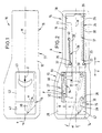
- a knife 10 has a knife housing 11, which from an upper housing shell 12 and from one lower housing shell 13 is composed. Both housing shells 12, 13 face each other with their hollow sides and are more appropriate in unspecified Attached to each other (e.g. detachable), for example by screwing or by clipping.
- Knife blade 14 Inside the cavity 46 of the lower shell 13 is a knife blade 14 Blade carrier 15 along the central axis labeled M, in the extension direction x and in the retraction direction z, translationally displaceable.
- the a partially visible main area (broad area) of the Knife blade 14 bears the reference number 47.
- the blade carrier 15 points in the area of the rear Handle extension 16 of the knife housing 11 a Guide extension 17 with a guide projection 18, which on the rectilinear inner surface 19 of the knife housing 11 is performed.
- the guide extension 17 On its two long sides the guide extension 17 each form a longitudinal recess 20, 21.
- the blade carrier has an eyelet 22 into which the front End 23 of a tension spring 24 is hooked.
- the back End 25 of the tension spring 24 is on one of the knife housing 11 formed pin 26 attached.
- the blade carrier 15 is partially from an operating part 27 subordinate, which is a separate Represents component.
- the actuator 27 is independent by the blade carrier 15 translationally linearly movable namely along a dash-dotted line Straight line L, which is also dash-dotted with represent central axis M an angle ⁇ forms.
- the actuating part 27 is along the straight line L. in the exit direction of the blade carrier 15 in the direction a and movable in direction e of the blade carrier 15 in the direction e.
- this has two guide pins to be addressed as link pins 28 on the underside of the actuating part 27 for Project the bottom 29 of the lower housing shell 13.
- the guide pins 28 protrude in the form of slot grooves to be addressed guide grooves 30, 31, which extend straight and into the bottom 29 of the bottom Housing shell 13 are embedded.
- the two Longitudinal axes LN of the two guide grooves 30, 31 are related the central axis M also at an angle ⁇ inclined.
- the actuating part 27 has on one long side one the blade carrier 15 on its narrow side H comprehensive approach 32, shown in longitudinal section is.
- the approach 32 forms on its narrow side H of the blade carrier 15 facing the inside K a primary coupling element P, while the narrow side H of the blade support 15 is a secondary coupling element S has.
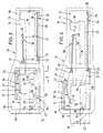
- the secondary coupling part S is according to the Fig. 2-7 from a recess on the narrow side H of the Blade carrier 15.
- the opening 36 of the recess has backwards in the direction of retreat z. So that the himself straight extending kink rod 34 in the unloaded Condition with its free end P in the undercut Can engage recess, the buckling bar 34th in the clamping point 33 a little towards the narrow side H of the blade carrier 15 arranged inclined.
- the operating part has 27 an eyelet 37 into which the front end 35 a tension spring 38 is hooked.
- the back end 39 of the tension spring 38 is on a pin 40 of the lower Housing shell 13 of the knife housing 11 attached.
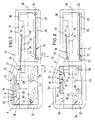
- the knife 10 shown functions as follows:
- the actuating part 27 is described above Way by means of its guide pin 28 in the housing side rectilinear guide grooves 30, 31 in one Angle ⁇ led to the central axis M.
- the actuator 27 is by means of the in the longitudinal recess 21st of the extension 17 arranged tension spring 38 in held its rear starting position A.
- the actuating part 27 has an actuating recess 41 of the upper housing shell 12 accessible Push handle handle 42, which the blade carrier 15 overlaps on the top and which with a Handle recess 43 is provided.
- the arrangement is like this met that on the neck 32 of the actuating part 27th the push handle handle 42 is fastened with one long side, is cohesively connected, such that the actuating part 27 a total Blade carrier 15 encompassing a C-shaped cross section having.
- the components 12, 13, 15, 27 and 42 form cast parts, So plastic injection or metal die-cast parts.
- Fig. 8 shows an alternative embodiment, at which, in geometrical inversion, the buckling bar 34 intrinsically elastic plastic and the blade carrier 15 is integrally formed.
- the recess is from the approach 32 of the actuator 27th educated.
Landscapes
- Life Sciences & Earth Sciences (AREA)
- Forests & Forestry (AREA)
- Engineering & Computer Science (AREA)
- Mechanical Engineering (AREA)
- Knives (AREA)
- Folding Of Thin Sheet-Like Materials, Special Discharging Devices, And Others (AREA)
- Nonmetal Cutting Devices (AREA)
Claims (28)
- Couteau (10) avec un boítier de couteau (11), dans lequel un support de lame (15), recevant une lame de couteau (14), est guidé avec possibilité de déplacement relatif, support de couteau déplaçable, à l'aide d'une manette d'actionnement (42), à l'encontre d'une force de rappel (ressort de traction 24) d'une position initiale (A), rétractée, protégée dans le boítier de couteau (11) de la lame de couteau (14), en une position de coupe, en saillie hors du boítier de couteau (11), de la lame de couteau (14), caractérisé en ce que la manette d'actionnement (42) est formée d'une partie d'actionnement (27) séparée, mobile par rapport au support de lame (15), et chargée, à l'encontre du déplacement de déploiement du support de lame (15), par une force de rappel (38) séparée, en ce que le support de lame (15) et la partie d'actionnement (27) à leur position initiale (A) sont couplés cinématiquement en entraínement au moyen d'un élément d'accouplement primaire (P) de la partie d'actionnement (27) ou du support de lame (15) et au moyen d'un élément d'accouplement secondaire (S) correspondant du support de lame (15) ou de la partie d'actionnement (27), uniquement dans le sens du déploiement (x) du support de lame (15), alors que, cependant, dans le sens de l'introduction du support de lame (15), elles sont hors de prise mutuelle, en ce que le déplacement de la partie d'actionnement (27) dans le sens du déploiement du support de lame (15) est limité et en ce que le support de lame (15) peut effectuer un déplacement relatif supplémentaire dans la direction de déploiement (x), déplacement plaçant hors de prise mutuelle les deux éléments d'accouplement (P, S).
- Couteau selon la revendication 1, caractérisé par un déplacement rectiligne de translation du support de lame (15).
- Couteau selon la revendication 1 ou selon la revendication 2, caractérisé par un déplacement rectiligne en translation de la partie d'actionnement (27).
- Couteau selon la revendication 1 ou selon la revendication 2, caractérisé par un déplacement en translation à trajectoire incurvée de la partie d'actionnement (27).
- Couteau selon l'une des revendications 1 à 4, caractérisé en ce que le déplacement de la partie d'actionnement (27) dans le sens du déploiement du support de lame (15) est limité par une butée (44).
- Couteau selon la revendication 5, caractérisé en ce que la butée (44) est formée par le boítier de couteau (11).
- Couteau selon l'une des revendications 1 à 6, caractérisé en ce que, suite au déplacement commun de la partie d'actionnement (27) et du support de lame (15) dans le sens du déploiement de ce dernier (15), un déplacement de commutation est préparé, au moyen duquel les deux parties d'accouplement (P, S) sont séparables l'une de l'autre.
- Couteau selon la revendication 7, caractérisé en ce que les deux éléments d'accouplement (P, S) sont séparables l'un de l'autre transversalement par rapport à leur trajectoire de déplacement.
- Couteau selon la revendication 7 ou la revendication 8, caractérisé en ce que le déplacement de commutation est préparé par le fait que l'allure des trajectoires de déplacement des deux éléments d'accouplement (P, S) est différente.
- Couteau selon la revendication 7 ou selon la revendication 8, caractérisé en ce que le déplacement de commutation est préparé au moyen de l'allure différente des trajectoires de déplacement du support de lame (15) et de la partie d'actionnement (27), y compris des éléments d'accouplement (S, P) leur étant associés.
- Couteau selon l'une des revendications 7 à 10, caractérisé en ce que le déplacement de commutation est préparé au moyen d'une commande à coulisse (30, 31, 28).
- Couteau selon la revendication 11, caractérisé en ce que la commande à coulisse (30, 31, 28) est associée à la partie d'actionnement (27) et au boítier de couteau (11).
- Couteau selon la revendication 12, caractérisé par au moins une fente de coulisse ou par au moins une rainure de guidage (30, 31), avec des tétons de guidage (28), chaque fois associés, l'allure longitudinale de la fente de coulisse ou bien la rainure de guidage (30, 31) dans la direction (a) de la partie d'actionnement (27) allant en divergeant par rapport à la direction de déploiement (x) du support de lame (15).
- Couteau selon la revendication 13, caractérisé en ce que la fente de coulisse ou bien la rainure de coulisse (30, 31) s'étend le long d'un plan disposé transversalement par rapport à une face principale (47) de la lame de couteau (14).
- Couteau selon la revendication 13, caractérisé en ce que la fente de coulisse ou la rainure de guidage (30, 31) s'étend le long d'un plan (10) posée dans ou parallèlement à la face principale (47) de la lame de couteau (14).
- Couteau selon l'une des revendications 12 à 15, caractérisé en ce que la commande de coulisse (30, 31, 28) associée à la partie d'actionnement (27) présente deux fentes de coulisse ou rainures de guidage (30, 31), avec deux tétons de guidage (28) correspondants, pour produire le déplacement de commutation.
- Couteau selon l'une des revendications 12 à 16, caractérisé en ce que la fente de coulissé respective ou la rainure de guidage (30, 31) respective est formée par le boítier de couteau (11), tandis que le téton de guidage (28) respectif est formé par la partie d'actionnement (27).
- Couteau selon l'une des revendications 7 à 17, caractérisé en ce que le déplacement de commutation pour assurer la séparation mutuelle des deux éléments d'accouplement (P, S) produit à titre préparatoire d'abord uniquement une énergie élastique potentielle qui, ensuite, est mise en oeuvre au cours du déplacement relatif supplémentaire du support de lame (15) dans la direction de déploiement (x).
- Couteau selon l'une des revendications 1 à 18, caractérisé en ce que l'un des deux éléments d'accouplement (S) est formé par un évidement, et l'autre des deux éléments d'accouplement (P) est formé par une saillie, encliquetable avec l'évidement, d'un élément de transmission de force et/ou de pression (34).
- Couteau selon la revendication 19, caractérisé en ce que l'élément de transmission de pression forme une tige à fléchissement (34) enserrée sur un côté, dont l'extrémité libre mobile constitue la saillie, réalisée sous la forme d'élément d'accouplement primaire (P) ou secondaire, coopérant avec un évidement réalisé sous la forme d'élément d'accouplement secondaire (S) et primaire.
- Couteau selon la.revendication 20, caractérisé en ce que la tige à fléchissement (34) est formée en métal élastique, en particulier en acier à ressort.
- Couteau selon la revendication 20, caractérisé en ce que la tige à fléchissement (34) est formée d'un seul tenant par la matière sur le support de lame (15) ou la partie d'actionnement (27) et, en particulier, est formée d'une matière synthétique présentant des propriétés élastiques.
- Couteau selon l'une des revendications 19 à 22, caractérisé en ce que l'évidement est prévu sur le support de lame (15) ou sur la partie d'actionnement (27).
- Couteau selon la revendication 23, caractérisé en ce que l'évidemen est formé d'un seul tenant sur le support de lame (15) ou la partie d'actionnement (27).
- Couteau selon l'une des revendications 1 à 24, caractérisé en ce que le support de lame (15) et la partie d'actionnement (27) sont disposés l'un à côté de l'autre dans des pans parallèles aux faces principales (47) de la lame de couteau (14).
- Couteau selon la revendication 24, caractérisé en ce que le support de lame (15) et la partie d'actionnement (27) sont disposés l'un à côté de l'autre dans des plans inclinés par rapport aux faces principales (47) de la lame de couteau (14).
- Couteau selon la revendication 25 ou selon la revendication 26, caractérisé en ce que la partie d'actionnement (27) forme sur un côté longitudinal un appendice (32) dépassant du support de lame (15) sur son côté étroit (H), appendice qui, forme sur sa face intérieure (K) tournée vers le côté étroit (H) du support de lame (15), le premier (P) ou l'autre (S) élément d'accouplement, tandis que le côté étroit (H) du support de lame (15) porte l'autre (S) ou le premier (P) élément d'accouplement.
- Couteau selon la revendication 27, caractérisé en ce que, sur l'appendice (32), la manette de prise de coulissement (42) est fixée par un côté longitudinal, en particulier et liée d'un seul tenant par la matière, de manière que la partie d'actionnement (27) présente une section en forme de C entourant le support de lame (15).
Applications Claiming Priority (2)
| Application Number | Priority Date | Filing Date | Title |
|---|---|---|---|
| DE19723279 | 1997-06-04 | ||
| DE19723279A DE19723279C1 (de) | 1997-06-04 | 1997-06-04 | Messer |
Publications (4)
| Publication Number | Publication Date |
|---|---|
| EP0882553A2 EP0882553A2 (fr) | 1998-12-09 |
| EP0882553A3 EP0882553A3 (fr) | 1998-12-23 |
| EP0882553B1 true EP0882553B1 (fr) | 2002-08-14 |
| EP0882553B8 EP0882553B8 (fr) | 2005-08-31 |
Family
ID=7831285
Family Applications (1)
| Application Number | Title | Priority Date | Filing Date |
|---|---|---|---|
| EP98105812A Expired - Lifetime EP0882553B8 (fr) | 1997-06-04 | 1998-03-31 | Couteau |
Country Status (6)
| Country | Link |
|---|---|
| US (1) | US6148520A (fr) |
| EP (1) | EP0882553B8 (fr) |
| JP (1) | JP3409177B2 (fr) |
| CN (1) | CN1091405C (fr) |
| DE (2) | DE19723279C1 (fr) |
| ES (1) | ES2181081T3 (fr) |
Families Citing this family (54)
| Publication number | Priority date | Publication date | Assignee | Title |
|---|---|---|---|---|
| DE19915934C1 (de) * | 1999-04-09 | 1999-12-09 | Beermann Kg Martor Argentax | Messer mit einem im wesentlichen hohlen Griffkörper zur Aufnahme und Führung eines Schiebers |
| US6560873B1 (en) * | 1999-11-12 | 2003-05-13 | Mel Wayne Ortner | Automatic safety knife |
| FR2810574B1 (fr) | 2000-06-27 | 2002-10-31 | Mure & Peyrot | Cutter a lame retractable automatiquement |
| FR2826898B1 (fr) * | 2001-07-06 | 2003-09-19 | Gerard Tremblay | Dispositif de coupe a lame retractable |
| DE10208345C1 (de) * | 2002-02-27 | 2003-08-21 | Beermann Kg Martor Argentax | Messer |
| USD499629S1 (en) | 2003-10-08 | 2004-12-14 | Rick Alvarez | Compact disc (CD)/box opener having an appearance of a CD case |
| US7467735B2 (en) * | 2004-10-29 | 2008-12-23 | Minuteman International, Inc. | Proportioning container |
| US20060130338A1 (en) * | 2004-12-17 | 2006-06-22 | Dzubak Donald J | Disposable box cutter |
| DE102004063046B3 (de) * | 2004-12-22 | 2006-03-09 | Martor Kg | Messer |
| DE102004063045B3 (de) * | 2004-12-22 | 2006-06-08 | Martor Kg | Messer |
| DE102005015962B3 (de) * | 2005-04-07 | 2006-10-19 | Wietscher, Norbert | Sicherheits-Schneidegerät (Kartonöffner) |
| US7797836B2 (en) * | 2005-08-02 | 2010-09-21 | The Stanley Works | Compact utility knife |
| US7316070B2 (en) * | 2005-11-15 | 2008-01-08 | Irwin Industrial Tool Company | Self-retracting utility knife |
| US20070157765A1 (en) * | 2006-01-09 | 2007-07-12 | Gabe Neiser | Package opener |
| JP4851242B2 (ja) * | 2006-06-06 | 2012-01-11 | オルファ株式会社 | セーフティカッターナイフ |
| US20080222900A1 (en) * | 2007-03-16 | 2008-09-18 | Anthony Lee | Apparatus for Emergency Seatbelt Release |
| US8250764B2 (en) * | 2007-04-16 | 2012-08-28 | Adco Industries-Technologies, L.P. | Adjustable utility knife |
| DE102007052060A1 (de) * | 2007-10-30 | 2009-05-07 | Martor Kg | Messer |
| DE102008019441A1 (de) * | 2008-04-17 | 2009-10-22 | Martor Kg | Messer |
| DE102008007090B3 (de) * | 2008-01-31 | 2009-05-07 | Martor Kg | Messer |
| AU2009208188B2 (en) * | 2008-01-31 | 2014-09-18 | Martor Kg | Knife |
| US7797838B2 (en) * | 2008-03-18 | 2010-09-21 | Taylor Brands, Llc | Retractable blade knife with opening assisted mechanism |
| DE102009050380A1 (de) | 2009-10-22 | 2011-04-28 | Martor Kg | Messer |
| US8732957B2 (en) * | 2008-04-17 | 2014-05-27 | Martor Kg | Retractile-blade utility knife |
| US9840013B2 (en) | 2008-04-29 | 2017-12-12 | Pacific Handy Cutter, Inc. | Safety cutter with blade change/storage mechanism |
| US8201336B2 (en) | 2008-05-02 | 2012-06-19 | Olympia Tools International, Inc. | Retractable utility knife |
| US20090277016A1 (en) * | 2008-05-07 | 2009-11-12 | Yuewei Wu | Utility knife with an auto-retractable blade |
| US8695221B2 (en) | 2008-08-21 | 2014-04-15 | Wen Hao | Utility knife with extended travel carriage |
| US8056241B2 (en) * | 2008-10-13 | 2011-11-15 | ADCO Industries—Technologies, L.P. | Utility cutter |
| WO2010096454A1 (fr) * | 2009-02-19 | 2010-08-26 | Liqui-Box Corporation | Dispositif de découpe de film à deux lames |
| US8375588B2 (en) * | 2009-04-27 | 2013-02-19 | Allway Tools, Inc. | Automatically retracting safety carton cutter |
| US8307556B2 (en) * | 2009-06-19 | 2012-11-13 | ADCO Industries—Technologies, L.P. | Utility cutter |
| DE102010023680A1 (de) | 2010-06-14 | 2011-12-15 | Martor Kg | Messer |
| DE102011007234B3 (de) * | 2011-04-12 | 2012-09-20 | Martor Kg | Sicherheits-Messer |
| US8732956B2 (en) | 2011-06-15 | 2014-05-27 | Aaron Paul McGushion | Safety locking mechanism for a utility knife |
| CN102825614B (zh) * | 2012-03-23 | 2016-04-06 | 上海美瑞实业有限公司 | 安全裁切刀 |
| US8769826B2 (en) * | 2012-07-11 | 2014-07-08 | Yuewei Wu | Cutting device |
| TWI466763B (zh) * | 2012-08-21 | 2015-01-01 | Hacksaw & Knife Manufactory Co Ltd | The blade automatically retracts the utility knife |
| US8782909B1 (en) | 2013-02-12 | 2014-07-22 | ADCO Industries—Technologies, L.P. | Utility cutter |
| DE102014208473B4 (de) * | 2014-05-06 | 2019-06-19 | Martor Kg | Messer mit automatischer Klingenrückstellung |
| US10814505B2 (en) * | 2014-05-06 | 2020-10-27 | Martor Kg | Knife with automatic blade retraction |
| CN104654308B (zh) * | 2015-01-09 | 2017-01-25 | 浙江理工大学 | 一种动物尸体处理装置 |
| TWM511938U (zh) * | 2015-08-21 | 2015-11-11 | 禾龍有限公司 | 能在刀柄同側面操控刀刃彈出及收合之彈簧輔助式刀具 |
| US9808941B2 (en) * | 2016-01-15 | 2017-11-07 | Klever Kutter Llc | Safety utility knife assemblies, and components for use within safety utility knifes |
| US10300615B2 (en) | 2016-04-06 | 2019-05-28 | Earl Votolato | Utility knife with improved safety features |
| US10245736B2 (en) * | 2017-04-28 | 2019-04-02 | Orange Hardware Company | Automatically retractable cutter |
| DE202017104154U1 (de) | 2017-07-12 | 2017-11-03 | Orange Hardware Company | Cuttermesser |
| US20190031135A1 (en) * | 2017-07-29 | 2019-01-31 | Wilson Gutierrez | Seat Belt Buckle With Built-in Cutter |
| US10632964B2 (en) | 2017-07-29 | 2020-04-28 | Wilson Gutierrez | Seatbelt buckle with built-in cutter |
| US11097434B2 (en) * | 2017-12-21 | 2021-08-24 | Mark Gordon Hooper | Utility knife |
| DE102018117203B4 (de) * | 2018-07-17 | 2024-02-01 | Martor Kg | Messer |
| DE102019131546B4 (de) * | 2019-11-21 | 2025-03-27 | Martor Kg | Messer |
| JP2024062303A (ja) * | 2022-10-24 | 2024-05-09 | まさみ 黒田 | 粘着テープ剥がし具 |
| US12600047B2 (en) * | 2023-02-27 | 2026-04-14 | Ritesafety Products International, Llc | Safety knife |
Family Cites Families (6)
| Publication number | Priority date | Publication date | Assignee | Title |
|---|---|---|---|---|
| US3999290A (en) * | 1976-03-15 | 1976-12-28 | Wood Jess W | Safety knife |
| DE3622342A1 (de) * | 1986-07-03 | 1988-01-14 | Beermann Kg Martor Argentax | Messer |
| DE4310037C1 (de) * | 1993-03-27 | 1993-12-09 | Beermann Kg Martor Argentax | Messer mit verschiebbarer Messerklinge |
| DE19507272C1 (de) * | 1995-03-03 | 1995-09-28 | Beermann Kg Martor Argentax | Kartonmesser |
| US5581890A (en) * | 1995-11-06 | 1996-12-10 | Great Neck Saw Manufacturers, Inc. | Utility knife |
| US5813121A (en) * | 1996-06-17 | 1998-09-29 | Allway Tools, Inc. | Automatically retractable utility knife |
-
1997
- 1997-06-04 DE DE19723279A patent/DE19723279C1/de not_active Expired - Lifetime
-
1998
- 1998-03-31 DE DE59805157T patent/DE59805157D1/de not_active Expired - Fee Related
- 1998-03-31 ES ES98105812T patent/ES2181081T3/es not_active Expired - Lifetime
- 1998-03-31 EP EP98105812A patent/EP0882553B8/fr not_active Expired - Lifetime
- 1998-05-06 JP JP15979498A patent/JP3409177B2/ja not_active Expired - Fee Related
- 1998-05-12 CN CN98108316A patent/CN1091405C/zh not_active Expired - Lifetime
- 1998-06-02 US US09/088,927 patent/US6148520A/en not_active Expired - Lifetime
Also Published As
| Publication number | Publication date |
|---|---|
| CN1091405C (zh) | 2002-09-25 |
| HK1016529A1 (en) | 1999-11-05 |
| CN1200973A (zh) | 1998-12-09 |
| EP0882553A3 (fr) | 1998-12-23 |
| JP3409177B2 (ja) | 2003-05-26 |
| EP0882553B8 (fr) | 2005-08-31 |
| DE19723279C1 (de) | 1998-04-23 |
| JPH114979A (ja) | 1999-01-12 |
| EP0882553A2 (fr) | 1998-12-09 |
| US6148520A (en) | 2000-11-21 |
| ES2181081T3 (es) | 2003-02-16 |
| DE59805157D1 (de) | 2002-09-19 |
Similar Documents
| Publication | Publication Date | Title |
|---|---|---|
| EP0882553B1 (fr) | Couteau | |
| DE19915934C1 (de) | Messer mit einem im wesentlichen hohlen Griffkörper zur Aufnahme und Führung eines Schiebers | |
| EP1340599B1 (fr) | Couteau | |
| DE69822160T2 (de) | Verbesserte injektionsspritze | |
| DE69218646T2 (de) | Injektionsvorrichtung | |
| EP0549847B1 (fr) | Couteau muni d'un porte-lame guidé pour déplacement longitudinal | |
| DE69401640T2 (de) | Haltevorrichtung mit Handgriff für Aerosolbehälter | |
| DE102004063045B3 (de) | Messer | |
| DE3051048C2 (de) | Klemmenmagazin zur Verwendung mit einem chirurgischen Instrument | |
| DE2736395B1 (de) | Messer mit einer laengsverschieblich gefuehrten zugfederbelasteten Messerklingenhalterung | |
| EP0252319A1 (fr) | Couteau à manche creux | |
| EP3319483B1 (fr) | Dispositif d'entraînement destiné à un élément de meuble mobile | |
| DE69010198T2 (de) | Rasierverfahren. | |
| EP0349870B1 (fr) | Appareil distributeur pour unités de rasage | |
| DE19750557A1 (de) | Einrichtung zum Einschlagen, Eintreiben und/oder Eindrehen von Schrauben | |
| DE19964314C2 (de) | Schlüssel, insbesondere für Kfz | |
| DE69318413T2 (de) | Zurückziehbares schreibgerät mit auswechselbarer patrone | |
| DE2951823A1 (de) | Ratschenschluessel | |
| DD295583A5 (de) | Vorrichtung zur ausgabe von plast-befestigungselementen | |
| DE202004017974U1 (de) | Chirurgisches Stanzinstrument | |
| DE3512747A1 (de) | Verfahren zum anbringen von befestigungseinrichtungen an gegenstaenden und vorrichtung zur durchfuehrung dieses anbringens | |
| DE69312834T2 (de) | Nadel für ein Ausgabegerät von Kunststoff-Befestigungselementen | |
| DE69418094T2 (de) | Trennbarer unterer Endanschlag für verdeckte Reissverschlüsse | |
| DE29709671U1 (de) | Messer | |
| DE202007008561U1 (de) | Entkoppelungsvorrichtung |
Legal Events
| Date | Code | Title | Description |
|---|---|---|---|
| PUAI | Public reference made under article 153(3) epc to a published international application that has entered the european phase |
Free format text: ORIGINAL CODE: 0009012 |
|
| PUAL | Search report despatched |
Free format text: ORIGINAL CODE: 0009013 |
|
| AK | Designated contracting states |
Kind code of ref document: A2 Designated state(s): BE DE ES FR GB NL |
|
| AX | Request for extension of the european patent |
Free format text: AL;LT;LV;MK;RO;SI |
|
| AK | Designated contracting states |
Kind code of ref document: A3 Designated state(s): AT BE CH DE DK ES FI FR GB GR IE IT LI LU MC NL PT SE |
|
| AX | Request for extension of the european patent |
Free format text: AL;LT;LV;MK;RO;SI |
|
| 17P | Request for examination filed |
Effective date: 19981209 |
|
| AKX | Designation fees paid |
Free format text: BE DE ES FR GB NL |
|
| GRAG | Despatch of communication of intention to grant |
Free format text: ORIGINAL CODE: EPIDOS AGRA |
|
| GRAG | Despatch of communication of intention to grant |
Free format text: ORIGINAL CODE: EPIDOS AGRA |
|
| GRAH | Despatch of communication of intention to grant a patent |
Free format text: ORIGINAL CODE: EPIDOS IGRA |
|
| 17Q | First examination report despatched |
Effective date: 20020207 |
|
| GRAH | Despatch of communication of intention to grant a patent |
Free format text: ORIGINAL CODE: EPIDOS IGRA |
|
| GRAA | (expected) grant |
Free format text: ORIGINAL CODE: 0009210 |
|
| AK | Designated contracting states |
Kind code of ref document: B1 Designated state(s): BE ES FR GB NL |
|
| REG | Reference to a national code |
Ref country code: GB Ref legal event code: FG4D Free format text: NOT ENGLISH |
|
| GBT | Gb: translation of ep patent filed (gb section 77(6)(a)/1977) |
Effective date: 20020814 |
|
| REF | Corresponds to: |
Ref document number: 59805157 Country of ref document: DE Date of ref document: 20020919 |
|
| ET | Fr: translation filed | ||
| RBV | Designated contracting states (corrected) |
Designated state(s): BE ES FR GB NL |
|
| REG | Reference to a national code |
Ref country code: ES Ref legal event code: FG2A Ref document number: 2181081 Country of ref document: ES Kind code of ref document: T3 |
|
| PLBE | No opposition filed within time limit |
Free format text: ORIGINAL CODE: 0009261 |
|
| STAA | Information on the status of an ep patent application or granted ep patent |
Free format text: STATUS: NO OPPOSITION FILED WITHIN TIME LIMIT |
|
| 26N | No opposition filed |
Effective date: 20030515 |
|
| NLT1 | Nl: modifications of names registered in virtue of documents presented to the patent office pursuant to art. 16 a, paragraph 1 |
Owner name: MARTOR KG |
|
| REG | Reference to a national code |
Ref country code: FR Ref legal event code: CD |
|
| REG | Reference to a national code |
Ref country code: FR Ref legal event code: PLFP Year of fee payment: 18 |
|
| REG | Reference to a national code |
Ref country code: FR Ref legal event code: PLFP Year of fee payment: 19 |
|
| REG | Reference to a national code |
Ref country code: FR Ref legal event code: PLFP Year of fee payment: 20 |
|
| PGFP | Annual fee paid to national office [announced via postgrant information from national office to epo] |
Ref country code: NL Payment date: 20170323 Year of fee payment: 20 Ref country code: FR Payment date: 20170323 Year of fee payment: 20 |
|
| PGFP | Annual fee paid to national office [announced via postgrant information from national office to epo] |
Ref country code: GB Payment date: 20170327 Year of fee payment: 20 Ref country code: BE Payment date: 20170323 Year of fee payment: 20 |
|
| PGFP | Annual fee paid to national office [announced via postgrant information from national office to epo] |
Ref country code: ES Payment date: 20170323 Year of fee payment: 20 |
|
| REG | Reference to a national code |
Ref country code: NL Ref legal event code: MK Effective date: 20180330 |
|
| REG | Reference to a national code |
Ref country code: BE Ref legal event code: MK Effective date: 20180331 |
|
| REG | Reference to a national code |
Ref country code: GB Ref legal event code: PE20 Expiry date: 20180330 |
|
| PG25 | Lapsed in a contracting state [announced via postgrant information from national office to epo] |
Ref country code: GB Free format text: LAPSE BECAUSE OF EXPIRATION OF PROTECTION Effective date: 20180330 |
|
| REG | Reference to a national code |
Ref country code: ES Ref legal event code: FD2A Effective date: 20200724 |
|
| PG25 | Lapsed in a contracting state [announced via postgrant information from national office to epo] |
Ref country code: ES Free format text: LAPSE BECAUSE OF EXPIRATION OF PROTECTION Effective date: 20180401 |