EP0882554A2 - Vorrichtung zum Schneiden von Zuschnitten aus einer blattförmigen Materialbahn - Google Patents
Vorrichtung zum Schneiden von Zuschnitten aus einer blattförmigen Materialbahn Download PDFInfo
- Publication number
- EP0882554A2 EP0882554A2 EP98830329A EP98830329A EP0882554A2 EP 0882554 A2 EP0882554 A2 EP 0882554A2 EP 98830329 A EP98830329 A EP 98830329A EP 98830329 A EP98830329 A EP 98830329A EP 0882554 A2 EP0882554 A2 EP 0882554A2
- Authority
- EP
- European Patent Office
- Prior art keywords
- anvil
- cutter
- cutting
- cutting position
- strip
- Prior art date
- Legal status (The legal status is an assumption and is not a legal conclusion. Google has not performed a legal analysis and makes no representation as to the accuracy of the status listed.)
- Withdrawn
Links
Images
Classifications
-
- B—PERFORMING OPERATIONS; TRANSPORTING
- B26—HAND CUTTING TOOLS; CUTTING; SEVERING
- B26D—CUTTING; DETAILS COMMON TO MACHINES FOR PERFORATING, PUNCHING, CUTTING-OUT, STAMPING-OUT OR SEVERING
- B26D1/00—Cutting through work characterised by the nature or movement of the cutting member or particular materials not otherwise provided for; Apparatus or machines therefor; Cutting members therefor
- B26D1/01—Cutting through work characterised by the nature or movement of the cutting member or particular materials not otherwise provided for; Apparatus or machines therefor; Cutting members therefor involving a cutting member which does not travel with the work
- B26D1/04—Cutting through work characterised by the nature or movement of the cutting member or particular materials not otherwise provided for; Apparatus or machines therefor; Cutting members therefor involving a cutting member which does not travel with the work having a linearly-movable cutting member
- B26D1/06—Cutting through work characterised by the nature or movement of the cutting member or particular materials not otherwise provided for; Apparatus or machines therefor; Cutting members therefor involving a cutting member which does not travel with the work having a linearly-movable cutting member wherein the cutting member reciprocates
- B26D1/08—Cutting through work characterised by the nature or movement of the cutting member or particular materials not otherwise provided for; Apparatus or machines therefor; Cutting members therefor involving a cutting member which does not travel with the work having a linearly-movable cutting member wherein the cutting member reciprocates of the guillotine type
- B26D1/09—Cutting through work characterised by the nature or movement of the cutting member or particular materials not otherwise provided for; Apparatus or machines therefor; Cutting members therefor involving a cutting member which does not travel with the work having a linearly-movable cutting member wherein the cutting member reciprocates of the guillotine type with a plurality of cutting members
- B26D1/095—Cutting through work characterised by the nature or movement of the cutting member or particular materials not otherwise provided for; Apparatus or machines therefor; Cutting members therefor involving a cutting member which does not travel with the work having a linearly-movable cutting member wherein the cutting member reciprocates of the guillotine type with a plurality of cutting members for thin material, e.g. for sheets, strips or the like
-
- B—PERFORMING OPERATIONS; TRANSPORTING
- B26—HAND CUTTING TOOLS; CUTTING; SEVERING
- B26D—CUTTING; DETAILS COMMON TO MACHINES FOR PERFORATING, PUNCHING, CUTTING-OUT, STAMPING-OUT OR SEVERING
- B26D3/00—Cutting work characterised by the nature of the cut made; Apparatus therefor
- B26D3/10—Making cuts of other than simple rectilinear form
-
- B—PERFORMING OPERATIONS; TRANSPORTING
- B65—CONVEYING; PACKING; STORING; HANDLING THIN OR FILAMENTARY MATERIAL
- B65H—HANDLING THIN OR FILAMENTARY MATERIAL, e.g. SHEETS, WEBS, CABLES
- B65H29/00—Delivering or advancing articles from machines; Advancing articles to or into piles
- B65H29/24—Delivering or advancing articles from machines; Advancing articles to or into piles by air blast or suction apparatus
- B65H29/241—Suction devices
- B65H29/242—Suction bands or belts
-
- B—PERFORMING OPERATIONS; TRANSPORTING
- B65—CONVEYING; PACKING; STORING; HANDLING THIN OR FILAMENTARY MATERIAL
- B65H—HANDLING THIN OR FILAMENTARY MATERIAL, e.g. SHEETS, WEBS, CABLES
- B65H2301/00—Handling processes for sheets or webs
- B65H2301/40—Type of handling process
- B65H2301/44—Moving, forwarding, guiding material
- B65H2301/445—Moving, forwarding, guiding material stream of articles separated from each other
- B65H2301/4454—Merging two or more streams
-
- B—PERFORMING OPERATIONS; TRANSPORTING
- B65—CONVEYING; PACKING; STORING; HANDLING THIN OR FILAMENTARY MATERIAL
- B65H—HANDLING THIN OR FILAMENTARY MATERIAL, e.g. SHEETS, WEBS, CABLES
- B65H2406/00—Means using fluid
- B65H2406/30—Suction means
- B65H2406/32—Suction belts
- B65H2406/323—Overhead suction belt, i.e. holding material against gravity
-
- Y—GENERAL TAGGING OF NEW TECHNOLOGICAL DEVELOPMENTS; GENERAL TAGGING OF CROSS-SECTIONAL TECHNOLOGIES SPANNING OVER SEVERAL SECTIONS OF THE IPC; TECHNICAL SUBJECTS COVERED BY FORMER USPC CROSS-REFERENCE ART COLLECTIONS [XRACs] AND DIGESTS
- Y10—TECHNICAL SUBJECTS COVERED BY FORMER USPC
- Y10T—TECHNICAL SUBJECTS COVERED BY FORMER US CLASSIFICATION
- Y10T83/00—Cutting
- Y10T83/202—With product handling means
- Y10T83/2092—Means to move, guide, or permit free fall or flight of product
- Y10T83/2192—Endless conveyor
- Y10T83/2194—And means to remove product therefrom
-
- Y—GENERAL TAGGING OF NEW TECHNOLOGICAL DEVELOPMENTS; GENERAL TAGGING OF CROSS-SECTIONAL TECHNOLOGIES SPANNING OVER SEVERAL SECTIONS OF THE IPC; TECHNICAL SUBJECTS COVERED BY FORMER USPC CROSS-REFERENCE ART COLLECTIONS [XRACs] AND DIGESTS
- Y10—TECHNICAL SUBJECTS COVERED BY FORMER USPC
- Y10T—TECHNICAL SUBJECTS COVERED BY FORMER US CLASSIFICATION
- Y10T83/00—Cutting
- Y10T83/485—Cutter with timed stroke relative to moving work
- Y10T83/49—Traveling cutter
-
- Y—GENERAL TAGGING OF NEW TECHNOLOGICAL DEVELOPMENTS; GENERAL TAGGING OF CROSS-SECTIONAL TECHNOLOGIES SPANNING OVER SEVERAL SECTIONS OF THE IPC; TECHNICAL SUBJECTS COVERED BY FORMER USPC CROSS-REFERENCE ART COLLECTIONS [XRACs] AND DIGESTS
- Y10—TECHNICAL SUBJECTS COVERED BY FORMER USPC
- Y10T—TECHNICAL SUBJECTS COVERED BY FORMER US CLASSIFICATION
- Y10T83/00—Cutting
- Y10T83/485—Cutter with timed stroke relative to moving work
- Y10T83/494—Uniform periodic tool actuation
-
- Y—GENERAL TAGGING OF NEW TECHNOLOGICAL DEVELOPMENTS; GENERAL TAGGING OF CROSS-SECTIONAL TECHNOLOGIES SPANNING OVER SEVERAL SECTIONS OF THE IPC; TECHNICAL SUBJECTS COVERED BY FORMER USPC CROSS-REFERENCE ART COLLECTIONS [XRACs] AND DIGESTS
- Y10—TECHNICAL SUBJECTS COVERED BY FORMER USPC
- Y10T—TECHNICAL SUBJECTS COVERED BY FORMER US CLASSIFICATION
- Y10T83/00—Cutting
- Y10T83/869—Means to drive or to guide tool
- Y10T83/8745—Tool and anvil relatively positionable
- Y10T83/8746—Straight line
Definitions
- the present invention relates to a device for cutting a strip of sheet material into blanks.
- the present invention relates to a device for cutting strip paper material, and finds application to advantage in the tobacco industry for the fabrication of internal reinforcing frames for cigarette packets, to which reference is made directly in the following specification albeit with no limitation in scope implied.
- the cutter is operated by a relative drive or actuator device in such a manner as to pass across the anvil in a direction transverse to that followed by the advancing strip and through the cutting station.
- the action of the cutter may be either continuous or reciprocating; if continuous, the cutter will be mounted generally to the periphery of a roller set in rotation about its own axis in such a way that the cutting edge is caused to describe a circular trajectory passing tangentially to the anvil at the cutting position.
- a relatively short active cutting step is accompanied by a relatively long passive feed step in which the cutting edge advances toward the cutting position, since the edge has to complete one full revolution about its axis of rotation between two successive cutting strokes.
- the cutter completes a forward stroke and a return stroke away from and back toward an at-rest position, passing through the cutting position each time.
- the forward stroke constitutes an operating step in which the cutting edge severs the paper strip by translating toward and striking against a corresponding edge of the anvil that coincides with the cutting position, whereas the return stroke is a passive movement serving simply to return the knife to the at-rest position.
- the object of the present invention is to provide a cutting device such as will be more efficient than devices of the prior art type described above.
- a device for cutting a strip of sheet material into blanks, of the type comprising an anvil, a cutter, first drive means by which the anvil and the cutter are set in relative cutting motion along a first predetermined direction and through a cutting position, and second drive means by which the strip is advanced toward the cutting position along a second predetermined direction substantially transverse to the first direction, characterized in that the anvil affords a central passage proportioned to accommodate the advancing strip, extending along the second direction and exhibiting an exit end that coincides with the cutting position, also in that the relative cutting motion is a reciprocating movement, and the first drive means are designed in such a way that the cutter can be halted relative to the anvil in two limit positions located on opposite sides of the central passage, in which the passage is vacated by the cutter.
- the cutter is reciprocated through a forward stroke and a return stroke, passing through the cutting position and severing the strip on the forward stroke and on the return stroke alike.
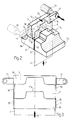
- 1 denotes a cutting device, in its entirety, comprising a cutter 2 and an anvil 3 coupled slidably in such a way as to cut through a strip 4 of paper material at a cutting position denoted 5.
- the anvil 3 is composed of two identical sections, denoted 3a and 3b, matched one to the other and disposed symmetrically on either side of a vertical plane A.
- the two anvil sections 3a and 3b afford respective flat surfaces breasted one with another parallel to the vertical plane A and separated by a distance marginally greater than the thickness of the paper strip 4, thus creating a passage 6 through which the strip 4 is made to advance when moving along a first predetermined direction 7, fed forward by a pinch roll device 8 of conventional embodiment.
- the passage 6 extends along the first direction 7 from an entry end 9 toward an exit end 10 that coincides with the cutting position 5.
- Each of the two anvil sections 3a and 3b exhibits a respective top surface 11a and 11b coupled slidably with a bottom surface 12 of the cutter 2, allowing movement along a second direction 13 transverse to the vertical plane A and to the first direction 7. More exactly, the cutter 2 appears substantially prismatic in embodiment with a trapezoidal profile, and the aforementioned bottom surface 12 exhibits a central recess proportioned to couple slidably with a matching central projection afforded by each of the two corresponding top surfaces 11a and 11b of the anvil.
- the same bottom surface 12 also combines with two lateral faces 14 of the cutter 2, disposed transversely to the second direction 13, to create two respective cutting edges 15 angled and shaped in such a way as to slice through the paper at the cutting position 5 and divide up the strip 4 into discrete blanks 16 each presenting the flat outline of an internal reinforcing frame as incorporated into cigarette packets of the type having a hinged lid (not illustrated).
- each arm 17 denotes one of two arms associated rigidly with the cutter 2, extending parallel to the vertical plane A from two opposite surfaces 18 of the cutter disposed transversely to the selfsame plane A.
- Each arm 17 is secured to the moving output member of a respective linear actuator 19.
- the function of the actuators is to reciprocate the cutter 2 along the second direction 13, through the cutting position 5 and between two limit positions in which both the cutting edges 15 are disposed on one side of the vertical plane A; that is to say, when occupying either one of the two limit positions, the cutter 2 remains coupled slidably with one only of the two anvil sections 3a or 3b, so that the exit end 10 of the passage 6 is left exposed.
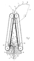
- the device 1 further comprises two aspirating type belt conveyors 20 of conventional embodiment, each extending through a respective transfer point 21 coinciding with one of the two aforementioned limit positions in such a way as to take up a blank 16 advanced by the corresponding face 14 of the cutter along the second direction 13 after passing through the cutting position 5.
- the two belt conveyors 20 extend substantially along the first direction 7, and combine geometrically with the anvil 3 to form an isosceles triangle in which the conveyors are the equal sides and the anvil provides the base.
- the function of the aspirating conveyors 20, which are also power driven, is to take up the discrete blanks 16 from the respective transfer points 21 and direct them toward a single transfer station 22 disposed at the vertex of the aforementioned triangle opposite to the base.
- the device 1 comprises a pocket conveyor 23 extending through the transfer station 22, which is power driven synchronously with the two aspirating belt conveyors 20 in such a way as to take up the blanks 16 singly and in alternation from these same two conveyors 20 at the transfer station 22.
- the strip 4 is advanced by the pinch roll device 8 along the first direction 7, through the passage 6 and out of the exit end 10 in such a way as to reach the cutting position 5 at a moment when the cutter 2 occupies either one of the two limit positions.
- the cutter 2 is now traversed by the actuators 19 along the second direction 13, through the cutting position 5 and toward the vacant limit position, with the result that the strip 4 is severed as the leading cutting edge 15 interacts with the relative anvil section 3a or 3 encountered along the second direction 13.
- the separated blank 16 will be carried by the advancing face 14 of the cutter 2 toward the corresponding transfer point 21, where it is taken up by the relative aspirating conveyor 20, carried toward the transfer station 22 and deposited in a pocket of the final conveyor 23.
- the successive step of returning the cutter 2 to the opposite limit position occurs in the same way as described above and therefore needs no further comment, other than to reiterate that the cutter 2, advantageously, separates two blanks from the strip during each full cycle of reciprocating movement.
- the operation of the pocket conveyor 23 is timed with that of the two aspirating belt conveyors 20 in such a manner that each two blanks 16 cut by two successive strokes of the cutter 2, away from and toward a given limit position, will be deposited in two successive pockets.
Landscapes
- Engineering & Computer Science (AREA)
- Mechanical Engineering (AREA)
- Life Sciences & Earth Sciences (AREA)
- Forests & Forestry (AREA)
- Making Paper Articles (AREA)
- Advancing Webs (AREA)
- Labeling Devices (AREA)
- Perforating, Stamping-Out Or Severing By Means Other Than Cutting (AREA)
Applications Claiming Priority (2)
| Application Number | Priority Date | Filing Date | Title |
|---|---|---|---|
| ITBO970328 | 1997-06-02 | ||
| IT97BO000328A IT1292593B1 (it) | 1997-06-02 | 1997-06-02 | Dispositivo per il taglio di un nastro di materiale in foglio in spezzoni |
Publications (2)
| Publication Number | Publication Date |
|---|---|
| EP0882554A2 true EP0882554A2 (de) | 1998-12-09 |
| EP0882554A3 EP0882554A3 (de) | 1999-11-24 |
Family
ID=11342304
Family Applications (1)
| Application Number | Title | Priority Date | Filing Date |
|---|---|---|---|
| EP98830329A Withdrawn EP0882554A3 (de) | 1997-06-02 | 1998-05-27 | Vorrichtung zum Schneiden von Zuschnitten aus einer blattförmigen Materialbahn |
Country Status (4)
| Country | Link |
|---|---|
| US (1) | US5974928A (de) |
| EP (1) | EP0882554A3 (de) |
| CN (1) | CN1200981A (de) |
| IT (1) | IT1292593B1 (de) |
Families Citing this family (3)
| Publication number | Priority date | Publication date | Assignee | Title |
|---|---|---|---|---|
| US6595216B1 (en) * | 2001-03-20 | 2003-07-22 | Brown & Williamson Tobacco Corporation | Method of cutting sheets of reconstituted tobacco |
| US8302457B2 (en) * | 2010-05-04 | 2012-11-06 | Carmanah Design And Manufacturing Inc. | Collision sensor for wood processing equipment |
| CN107399104B (zh) * | 2017-08-31 | 2018-11-27 | 重庆三创印刷有限公司 | 一种模切装置 |
Family Cites Families (10)
| Publication number | Priority date | Publication date | Assignee | Title |
|---|---|---|---|---|
| DE489561C (de) * | 1925-06-23 | 1930-01-20 | Saechsische Cartonnagen Maschi | Vorrichtung zum Abtrennen von Bogen, einzelnen Werkstuecken o. dgl. von einer fortlaufend oder absatzweise zugefuehrten Materialbahn, wie Papier, Pappe o. dgl. |
| US2757733A (en) * | 1948-03-24 | 1956-08-07 | Standard Brands Inc | Double edged reciprocable cutting device |
| US3483780A (en) * | 1967-07-19 | 1969-12-16 | Nypel Inc | Cutter |
| DE2258574A1 (de) * | 1972-11-30 | 1974-06-06 | Hilbert Paetzold | Gesteuerte wendemesser-traverse fuer heb- und senkschnitt an fliessendem material |
| IT1001427B (it) * | 1973-12-20 | 1976-04-20 | Gd Spa | Dispositivo per la produzione dei cosidetti elementi interni o col letti nelle macchine condizionatri ci di sigarette in pacchetti rigidi del tipo a coperchio incernierato |
| GB1441993A (en) * | 1974-01-02 | 1976-07-07 | Simon Ltd Henry | Device for cutting sheet material |
| DE3216770A1 (de) * | 1982-05-05 | 1983-11-10 | Rose Verpackungsmaschinenfabrik Theegarten GbmH & Co, 5000 Köln | Vorrichtung zum abschneiden von stuecken, insbesondere von bonbons, von einem insbesondere weichplastischen massestrang |
| GB8309038D0 (en) * | 1983-03-31 | 1983-05-11 | Chambon Ltd | Guide apparatus for carton blank delivery system |
| DE4323732C2 (de) * | 1993-07-15 | 1995-08-10 | Heil Gmbh & Co Kg Geb | Einrichtung zur gleichzeitigen Herstellung einer Anzahl von gefalteten Tüchern |
| JPH08257982A (ja) * | 1995-03-22 | 1996-10-08 | Ryowa Kk | 食品スライス機 |
-
1997
- 1997-06-02 IT IT97BO000328A patent/IT1292593B1/it active IP Right Grant
-
1998
- 1998-05-27 EP EP98830329A patent/EP0882554A3/de not_active Withdrawn
- 1998-05-29 CN CN98109386A patent/CN1200981A/zh active Pending
- 1998-06-02 US US09/089,139 patent/US5974928A/en not_active Expired - Fee Related
Also Published As
| Publication number | Publication date |
|---|---|
| ITBO970328A0 (it) | 1997-06-02 |
| IT1292593B1 (it) | 1999-02-08 |
| CN1200981A (zh) | 1998-12-09 |
| US5974928A (en) | 1999-11-02 |
| ITBO970328A1 (it) | 1998-12-02 |
| EP0882554A3 (de) | 1999-11-24 |
Similar Documents
| Publication | Publication Date | Title |
|---|---|---|
| US4671152A (en) | Apparatus for cutting out windows in envelopes | |
| US4922775A (en) | Device for cutting contoured labels | |
| US7896792B2 (en) | Packaging machine and method for cutting packages | |
| CA1176123A (en) | Envelope processing machine and method | |
| US5974928A (en) | Device for cutting a strip of sheet material into blanks | |
| CN110650892B (zh) | 用于卧式自动包装机的机头 | |
| EP1153836B1 (de) | Vorrichtung zum Schneiden von Blisterverpackungen in einer Blisterverpackungsmaschine | |
| JPH11347828A (ja) | 帯刃加工方法 | |
| JPH0155957B2 (de) | ||
| US2636423A (en) | Machine for making partitions | |
| US8584562B2 (en) | Method and device for cutting a bone containing material string into slices | |
| US4209956A (en) | Forming overlapped wrappers | |
| US6719679B1 (en) | Perforation device | |
| US4299151A (en) | Cutting mechanism for a packaging machine | |
| US4648299A (en) | Apparatus for cutting off a tear-open strip | |
| US4173161A (en) | Trim press | |
| US3824907A (en) | Synchronized paper web transport and connecting strap cutting and positioning apparatus | |
| JP5080684B1 (ja) | 耳落とし装置 | |
| JP7381431B2 (ja) | スクラップカッター | |
| US5138861A (en) | Method and apparatus for cutting corrugated webs | |
| CN212581116U (zh) | 一种口罩打片机 | |
| CN108749134A (zh) | 双飞刀去边装置和包装袋生产线 | |
| JPH01133613A (ja) | 非円形断面を有する箱体の製造方法および製造装置 | |
| EP1588833A1 (de) | Schneideinheit zum Abtrennen von Zuschnitten für Krägen von steifen Zigarettenverpackungen | |
| US5699709A (en) | Device for severing packing strips having blisters from a continuous film |
Legal Events
| Date | Code | Title | Description |
|---|---|---|---|
| PUAI | Public reference made under article 153(3) epc to a published international application that has entered the european phase |
Free format text: ORIGINAL CODE: 0009012 |
|
| AK | Designated contracting states |
Kind code of ref document: A2 Designated state(s): AT BE CH CY DE DK ES FI FR GB GR IE IT LI LU MC NL PT SE |
|
| AX | Request for extension of the european patent |
Free format text: AL;LT;LV;MK;RO;SI |
|
| PUAL | Search report despatched |
Free format text: ORIGINAL CODE: 0009013 |
|
| AK | Designated contracting states |
Kind code of ref document: A3 Designated state(s): AT BE CH CY DE DK ES FI FR GB GR IE IT LI LU MC NL PT SE |
|
| AX | Request for extension of the european patent |
Free format text: AL;LT;LV;MK;RO;SI |
|
| STAA | Information on the status of an ep patent application or granted ep patent |
Free format text: STATUS: THE APPLICATION HAS BEEN WITHDRAWN |
|
| 18W | Application withdrawn |
Withdrawal date: 20000219 |