EP0882665A2 - Regelung von Fördereinrichtungen in einer Aufzeichnungsvorrichtung - Google Patents
Regelung von Fördereinrichtungen in einer Aufzeichnungsvorrichtung Download PDFInfo
- Publication number
- EP0882665A2 EP0882665A2 EP98109807A EP98109807A EP0882665A2 EP 0882665 A2 EP0882665 A2 EP 0882665A2 EP 98109807 A EP98109807 A EP 98109807A EP 98109807 A EP98109807 A EP 98109807A EP 0882665 A2 EP0882665 A2 EP 0882665A2
- Authority
- EP
- European Patent Office
- Prior art keywords
- recording medium
- recording
- conveying means
- roller
- pinching
- Prior art date
- Legal status (The legal status is an assumption and is not a legal conclusion. Google has not performed a legal analysis and makes no representation as to the accuracy of the status listed.)
- Granted
Links
Images





Classifications
-
- B—PERFORMING OPERATIONS; TRANSPORTING
- B41—PRINTING; LINING MACHINES; TYPEWRITERS; STAMPS
- B41J—TYPEWRITERS; SELECTIVE PRINTING MECHANISMS, i.e. MECHANISMS PRINTING OTHERWISE THAN FROM A FORME; CORRECTION OF TYPOGRAPHICAL ERRORS
- B41J11/00—Devices or arrangements of selective printing mechanisms, e.g. ink-jet printers or thermal printers, for supporting or handling copy material in sheet or web form
- B41J11/0095—Detecting means for copy material, e.g. for detecting or sensing presence of copy material or its leading or trailing end
-
- B—PERFORMING OPERATIONS; TRANSPORTING
- B41—PRINTING; LINING MACHINES; TYPEWRITERS; STAMPS
- B41J—TYPEWRITERS; SELECTIVE PRINTING MECHANISMS, i.e. MECHANISMS PRINTING OTHERWISE THAN FROM A FORME; CORRECTION OF TYPOGRAPHICAL ERRORS
- B41J11/00—Devices or arrangements of selective printing mechanisms, e.g. ink-jet printers or thermal printers, for supporting or handling copy material in sheet or web form
- B41J11/007—Conveyor belts or like feeding devices
Definitions
- the present invention relates to a recording apparatus for recording an image on a recording medium supplied one by one.
- Fig. 10 shows a conventional color recording apparatus of ink jet recording type.
- the recording apparatus serves to record a color image on a small size recording medium from a visiting card to a post card.
- the recording apparatus includes a sheet supply portion 200 for supplying recording media S one by one to a main body 100 of the recording apparatus, a recording convey portion 300 for conveying the recording medium S supplied from the sheet supply portion 200 at a predetermined speed in a horizontal direction, an image recording portion 400 for recording an image on the recording medium S being conveyed by the recording convey portion 300, and a discharge stacking portion 500 for discharging and stacking the recording media S on which the images were recorded in the image recording portion 400.
- the sheet supply portion 200 comprises a sheet supply tray 201, a pick-up roller 202, a separation pad 203, a pair of separation supply rollers 204, 205, and a shutter 206.
- the pick-up roller 202 is rotated in a clockwise direction to feed out the recording media S stacked on the sheet supply tray 201 from an uppermost one.
- the sheet supply tray 201 is lifted by a predetermined amount whenever a predetermined number of recording media S are fed out, so that the uppermost recording medium S is contacted with the pick-up roller 202 with predetermined pressure.
- the recording media S fed out by the pick-up roller 202 are pre-separated by the inclined separation pad 203 and then are separated and supplied one by one by the pair of separation supply rollers 204, 205.
- the supply roller 205 is rotated in a clockwise direction.
- the separation roller 204 is normally rotated in an anti-clockwise direction. However, if a plurality of recording media S are supplied in a nip between the supply roller 205 and the separation roller 204, the separation roller is rotated in a clockwise direction by the action of a torque limiter (not shown). Skew-feed of the recording medium S fed by the pair of separation supply rollers 204, 205 is corrected by abutting the recording medium against the shutter a tip end of which blocks a sheet path. After the skew-feed of the recording medium is corrected, the shutter 206 is retarded from the sheet path.
- the recording convey portion 300 includes an endless convey belt 301, a driven roller 302 cooperating with the convey belt 301 to pinch the recording medium S therebetween at a most upstream end of the convey belt, and a plurality of spur wheels 303 to 307 for holding down the recording medium S on the convey belt 301 at a downstream area of the driven roller 302.
- the convey belt 301 is mounted and wound around a drive roller 308 rotated in an anti-clockwise direction and a driven roller 308 and extends in a horizontal direction.
- the driven roller 302 is opposed to the drive roller 308 and is biased toward the drive roller 308 by a biasing means (not shown) such as a spring so that the driven roller 302 is contacted with the convey belt 301 with predetermined pressure.
- the tip end of the recording sheet S the skew-feed of which was corrected by the shutter 206 enters into a nip between the convey belt 301 rotated in the anti-clockwise direction and the driven roller 302 rotatingly driven by the rotation of the convey belt 301.
- the recording medium S is conveyed onto the convey belt 301 while being pinched between the convey belt 301 and the driven roller 302.
- the recording medium S on the convey belt 301 rotated in the anticlockwise direction is conveyed toward a downstream side while being held down by the spur wheels 303 to 307 rotatingly driven by the rotation of the convey belt 301.
- the image recording portion 400 includes a plurality of ink jet recording heads 400B, 400C, 400M and 400Y spaced apart from each other by a predetermined distance along a recording medium conveying direction.
- the recording head 400B serves to discharge black color ink
- recording head 400C serves to discharge cyan color ink
- recording head 400M serves to discharge magenta color ink
- recording head 400Y serves to discharge yellow color ink.
- the recording head 400B discharges the black color ink, thereby recording a black color image. Then, when the recording medium S reaches the recording head 400C, the recording head 400C discharges the cyan color ink, thereby recording a cyan color image. Then, when the recording medium S reaches the recording head 400M, the recording head 400M discharges the magenta color ink, thereby recording a magenta color image. Then, when the recording medium S reaches the recording head 400Y, the recording head 400Y discharges the yellow color ink, thereby recording an yellow color image.
- the discharge stacking portion 500 includes a sheet discharge tray 501, a first discharge roller 502, and a second discharge roller 503.
- the recording medium S on which the image was recorded is discharged out of the apparatus while being pinched between the first discharge roller 502 and a spurred roller 504.
- the recording medium S discharged out of the apparatus is discharged onto the sheet discharge tray 501 while being pinched between the second discharge roller 503 and a spurred roller 505.
- the recording medium S-2 being conveyed by the convey belt 301 and being recorded is subjected to conveyance resistance at a time when a trail end of the recording medium leaves the nip between the convey belt 301 and the driven roller 302, thereby worsening the recording quality.
- the above first and second problems are noticeable particularly when the recording medium S is a thick sheet having a thickness of 200 microns or more.
- the present invention aims to eliminate the above-mentioned conventional drawbacks, and an object of the present invention is to provide a recording apparatus in which a recording medium can be stably conveyed to a recording portion.
- the present invention relates to a recording apparatus having a first recording medium conveying means for conveying the recording medium received in a pinched condition to the recording portion in a pinched condition, and a second recording medium conveying means for conveying the recording medium to the first recording medium conveying means in a born condition.
- a recording apparatus wherein, when a tip end of a recording medium conveyed by the second recording medium conveying means is passed through a pinching portion of the first recording medium conveying means, a recording medium pinching condition of the second recording medium conveying means is released.
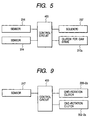
- Fig. 1 shows a main portion of a recording apparatus to which the present invention is applied and which is similar to the recording apparatus as shown in Fig. 10. Further, Fig. 5 shows a control block diagram.
- a recording medium pinching condition between a separation roller 204 and a supply roller 205-1 which serve to convey a recording medium S while pinching the recording medium therebetween and a recording medium pinching condition between a convey belt 301 and a driven roller 302-1 which serve to convey a recording medium S while pinching the recording medium therebetween can be released.
- the recording medium pinching condition is released by disengaging the supply roller 205-1 from the separation roller 204.
- the recording medium pinching condition is released by disengaging the driven roller 302-1 from the convey belt 301.
- the supply roller (roller A) 205-1 is disengaged from the separation roller (roller B) 204 by means of a solenoid 207.
- the supply roller 205-1 can be shifted in an up-and-down direction and is biased toward the separation roller 204 by an endless coil spring 210 mounted around a bearing 208 of the supply roller 205-1 and a bearing 209 of the separation roller 204 so that the supply roller 205-1 is contacted with the separation roller 204 with predetermined pressure.
- An iron core 211 of the solenoid 207 is connected to a rotary shaft 214 supported by a bearing 213 at a predetermined position via a link 212.
- the link 212 is supported for rotation with respect to the iron core 211 and is fixed with respect to the rotary shaft 214 not to be rotated relative to the latter.
- a lever 215 for transmitting movement of the rotary shaft 214 to the supply roller 205-1 is disposed between the rotary shaft 214 and the bearing 208. One end of the lever 215 is fixed to the rotary shaft 214 and the other end of the lever is fixed to the bearing 208.
- Fig. 1 shows a condition that the solenoid 207 is turned OFF.
- the supply roller 205-1 is contacted with the separation roller 204 by the biasing force of the coil spring 210 so that the iron core 211 of the solenoid 207 is extended.
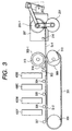
- Fig. 3 shows a condition that the solenoid 207 is turned ON.
- the driven roller (roller D) 302-1 is disengaged from the convey belt by a dome-shaped cam 310 attached to one lateral end of a drive roller shaft 311 (refer to Fig. 2).
- a driving force of the shaft 311 is transmitted to the cam 310 through a cam drive clutch 310a (Fig. 2).
- a sub-roller 313 is attached to a driven roller shaft 312 in an opposed relation to the cam 310.
- Fig. 1 shows a condition that the cam drive clutch 310a is in an OFF condition, and, in this condition, the cam 310 is in a stand-by condition directing downwardly (six o'clock position).
- the cam drive clutch 310a When the cam drive clutch 310a is turned ON, the cam 310 to which the driving force of the shaft 311 was transmitted is rotated in an anti-clockwise direction to gradually lift the sub-roller 313.
- the cam 310 is rotated by 180 degrees to occupy an upwardly directed position (twelve o'clock position), the cam drive clutch is turned OFF.
- Fig. 4 shows a condition that the cam drive clutch 310a is turned ON.
- recording medium detect sensors (optical sensors) 216, 314 for detecting the recording medium S are disposed between the nip of the separation roller 204/supply roller 205-1 and the nip of the convey belt 301/driven roller 302-1 and immediately at a downstream side of the nip of the convey belt 301/driven roller 302-1, respectively.
- the solenoid 207 is turned OFF and the cam drive clutch 310a is turned OFF, with the result that, as shown in Fig. 1, the supply roller 205-1 is contacted with the separation roller 204 to form the nip therebetween and the driven roller 302-1 is contacted with the convey belt 301 to form the nip therebetween.
- the recording medium fed out from the sheet supply tray 201 passes through the nip between the separation roller 204 and the supply roller 205-1 and then passes through the nip between the convey belt 301 and the driven roller 302-1.
- a control circuit 400 turns the solenoid 207 ON, thereby disengaging the supply roller 205-1 from the separation roller 204.
- the convey belt 301 is not subjected to the influence of the pair of separation supply rollers 204, 205-1 via the recording medium S-1, and, thus, the recording medium S-2 being conveyed by the convey belt 301 and being recorded is conveyed stably at a predetermined speed.
- the trail end of the recording medium S-1 is detected by the recording medium detect sensor (recording medium detect means B) 216, the control circuit 400 turns the solenoid 207 OFF and at the same time turns the cam drive clutch 310a ON for a predetermined time period.
- Fig. 4 shows a condition when the predetermined time period is elapsed after the cam drive clutch 310a was turned ON.
- the cam 310 is stopped at the upwardly directing position, with the result that the driven roller 302-1 is disengaged from the convey belt 301.
- the trail end of the recording medium S-2 being conveyed by the convey belt 301 and being recorded is not yet passed through the nip between the convey belt 301 and the driven roller 302-1. Accordingly, when the trail end of the recording medium S-2 leaves the nip between the convey belt 301 and the driven roller 302-1, the recording medium is not subjected to the conveyance resistance from the driven roller 302-1.
- the control circuit 400 turns the cam drive clutch 310a ON for the predetermined time period.
- the cam 310 is rotated in the anti-clockwise direction up to the downwardly directing position (refer to Fig. 1), thereby contacting the driven roller 302-1 with the convey belt 301.
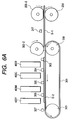
- Fig. 6A shows a main portion of a recording apparatus to which the present invention is applied and which is similar to the recording apparatus as shown in Fig. 10.
- semi-circular or D-cut rollers each having a flat surface at a portion of the periphery thereof are used as a supply roller (roller C) 205-2 cooperating with a separation roller 204 to pinch and convey a recording medium S therebetween, and a driven roller (roller E) 302-2 cooperating with a convey belt 301 204 to pinch and convey a recording medium S therebetween.
- the driven roller 302-2 shaped as a cam having a radius gradually decreasing in an anti-clockwise direction.
- a driving force is transmitted to the supply roller 205-2 and the driven roller 302-2 through one revolution clutches 205-2a, 302-2a, respectively (refer to Figs. 6B and 6C).
- a recording medium detect sensor (recording medium detect means C) 217 for detecting the recording medium S is disposed between a nip of the separation roller 204/supply roller 205-2 and a nip of he convey roller 301/driven roller 302-2.
- the semi-circular supply roller 205-2 and the semi-circular driven roller 302-2 are in their stand-by conditions where the flat surfaces faces downwardly (becomes parallel with the recording medium).
- the one revolution clutch 205-2a one revolution clutch A
- the control circuit 400 thereby rotating the supply roller 205-2 in a clockwise direction.
- the recording medium fed out from a sheet supply tray 201 is passed through the nip between the separation roller 204 and the supply roller 205-2.
- the one revolution clutch 302-2a (one revolution clutch B) is turned ON by the control circuit 400, thereby rotating the driven roller 302-2 in a clockwise direction.
- the tip end of the recording medium S-1 is passed through the nip between the convey belt 301 and the driven roller 302-2.
- Figs. 6A to 6C show conditions immediately after the tip end of the recording medium S-1 is passed through the nip between the convey belt 301 and the driven roller 302-2.
- the supply roller 205-2 has already been rotated by one revolution to return to the stand-by condition. That is to say, the recording medium pinching condition between the separation roller 204 and the supply roller 205-2 has been released.
- the convey belt 301 is not subjected to the influence of the pair of separation supply rollers 204, 205-2 via the recording medium S-1, and, thus, the recording medium S-2 being conveyed by the convey belt 301 and being recorded is conveyed stably at a predetermined speed.
- Fig. 7 shows a condition immediately before one revolution of the driven roller 302-2 is completed.
- the recording medium S-1 which starts to be conveyed by the convey belt 301 is held down by a spur wheel 303. Since the radius of the driven roller 302-2 is decreased as the driven roller is rotated, at the condition shown in Fig. 7, the driven roller 302-2 is contacted with the recording medium S-1 with weak pressure.
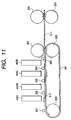
- Fig. 8 shows a condition that the driven roller 302-2 has been rotated by one revolution to return the stand-by condition.
- the trail end of the recording medium S-1 is not yet passed through the nip between the convey belt 301 and the driven roller 302-2, since the recording medium pinching condition between the convey belt 301 and the driven roller 302-2 is released, the recording medium S-1 is not subjected to the conveyance resistance from the driven roller 302-2.
- the recording medium pinching condition of the second recording medium conveying means is released when the recording medium conveyed from the second recording medium conveying means is pinched by the first recording medium conveying means for pinching and conveying the recording medium to the recording portion, the first recording medium conveying means is not subjected to the influence of the second recording medium conveying means via the recording medium.
- the recording medium pinching condition of the first recording medium conveying means is released before the trail end of the recording medium conveyed from the second recording medium conveying means is passed through the pinching portion of the first recording medium conveying means, the recording medium being conveyed by the first recording medium conveying means is not subjected to the conveyance resistance from the pinching portion.
- the recording medium being conveyed by the first recording medium conveying means is stably conveyed at the predetermined speed.
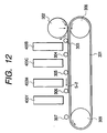
- the recording medium (not shown) is passed through a nip of a pair of separation supply rollers 204, 205-1 and enters into a nip between a convey belt 301 and a driven roller 302-1. Thereafter, the recording medium is conveyed by the convey belt 301 while being held down by spur wheels 303 to 307 and is passed through a recording portion including various color recording heads 400B, 400C, 400M and 400Y.
- the supply roller 205-1 is disengaged from the separation roller 204, so that the convey belt 301 is not subjected to the influence of the pair of separation supply rollers 204, 205-1 via the recording medium. Further, when a trail end of the recording medium is detected by a recording medium detect sensor 216, the driven roller 302-1 is disengaged from the convey belt 301, so that the recording medium is not subjected to conveyance resistance from the driven roller 302-1.
Landscapes
- Delivering By Means Of Belts And Rollers (AREA)
- Handling Of Cut Paper (AREA)
- Handling Of Sheets (AREA)
- Ink Jet (AREA)
Applications Claiming Priority (3)
| Application Number | Priority Date | Filing Date | Title |
|---|---|---|---|
| JP9142779A JPH10329972A (ja) | 1997-05-30 | 1997-05-30 | 記録装置 |
| JP142779/97 | 1997-05-30 | ||
| JP14277997 | 1997-05-30 |
Publications (3)
| Publication Number | Publication Date |
|---|---|
| EP0882665A2 true EP0882665A2 (de) | 1998-12-09 |
| EP0882665A3 EP0882665A3 (de) | 1999-03-24 |
| EP0882665B1 EP0882665B1 (de) | 2003-08-13 |
Family
ID=15323403
Family Applications (1)
| Application Number | Title | Priority Date | Filing Date |
|---|---|---|---|
| EP98109807A Expired - Lifetime EP0882665B1 (de) | 1997-05-30 | 1998-05-28 | Regelung von Fördereinrichtungen in einer Aufzeichnungsvorrichtung |
Country Status (4)
| Country | Link |
|---|---|
| US (1) | US6137600A (de) |
| EP (1) | EP0882665B1 (de) |
| JP (1) | JPH10329972A (de) |
| DE (1) | DE69817083T2 (de) |
Cited By (2)
| Publication number | Priority date | Publication date | Assignee | Title |
|---|---|---|---|---|
| EP1693219A1 (de) * | 2005-02-21 | 2006-08-23 | Brother Kogyo Kabushiki Kaisha | Bilderzeugungsgerät |
| US10792936B2 (en) * | 2018-02-23 | 2020-10-06 | Ricoh Company, Ltd. | Coating device, image forming apparatus, and image forming system |
Families Citing this family (10)
| Publication number | Priority date | Publication date | Assignee | Title |
|---|---|---|---|---|
| US6749721B2 (en) | 2000-12-22 | 2004-06-15 | Kimberly-Clark Worldwide, Inc. | Process for incorporating poorly substantive paper modifying agents into a paper sheet via wet end addition |
| US6916402B2 (en) | 2002-12-23 | 2005-07-12 | Kimberly-Clark Worldwide, Inc. | Process for bonding chemical additives on to substrates containing cellulosic materials and products thereof |
| US7670459B2 (en) | 2004-12-29 | 2010-03-02 | Kimberly-Clark Worldwide, Inc. | Soft and durable tissue products containing a softening agent |
| JP2006231862A (ja) * | 2005-02-28 | 2006-09-07 | Brother Ind Ltd | 画像形成装置 |
| JP2006272772A (ja) * | 2005-03-29 | 2006-10-12 | Brother Ind Ltd | 画像記録装置 |
| DE102006014091A1 (de) * | 2006-03-24 | 2007-10-11 | Eastman Kodak Co. | Vorrichtung zum Transport von Bögen |
| JP4329835B2 (ja) * | 2007-03-28 | 2009-09-09 | ブラザー工業株式会社 | 画像記録装置 |
| JP6149465B2 (ja) * | 2013-03-29 | 2017-06-21 | ブラザー工業株式会社 | 液体吐出装置 |
| JP6358439B2 (ja) * | 2015-05-28 | 2018-07-18 | 京セラドキュメントソリューションズ株式会社 | 画像形成装置、画像形成方法及び制御プログラム |
| EP3571054B1 (de) * | 2017-01-23 | 2020-10-07 | Koenig & Bauer AG | Verfahren zum betreiben einer bogenbearbeitungsmaschine und eine bogenbearbeitungsmaschine |
Family Cites Families (16)
| Publication number | Priority date | Publication date | Assignee | Title |
|---|---|---|---|---|
| JPS57141941U (de) * | 1981-02-28 | 1982-09-06 | ||
| JP2689469B2 (ja) * | 1988-04-08 | 1997-12-10 | セイコーエプソン株式会社 | プリンタ紙送り機構 |
| US5091754A (en) * | 1989-04-26 | 1992-02-25 | Canon Kabushiki Kaisha | Image forming apparatus comprising lateral movement means |
| US5183347A (en) * | 1989-12-15 | 1993-02-02 | Kabushiki Kaisha Toshiba | Apparatus for printing images on booklets |
| JPH04213537A (ja) * | 1990-12-11 | 1992-08-04 | Ricoh Co Ltd | 電子写真装置 |
| US5298959A (en) * | 1991-11-08 | 1994-03-29 | Canon Kabushiki Kaisha | Image forming apparatus with re-feeding means |
| JPH0568991U (ja) * | 1991-12-17 | 1993-09-17 | 株式会社新興製作所 | 印字媒体搬送装置 |
| DE4205777C2 (de) * | 1992-02-21 | 1994-10-13 | Mannesmann Ag | Drucker für die Verarbeitung von Aufzeichnungsträgern unterschiedlicher Dicke in Form von Einzelblättern und Endlosbahnen |
| US5499091A (en) * | 1993-04-19 | 1996-03-12 | Canon Kabushiki Kaisha | Image forming apparatus having a counting device to facilitate two-sided copying |
| JPH0733279A (ja) * | 1993-07-16 | 1995-02-03 | Canon Inc | 記録装置 |
| JP3307472B2 (ja) * | 1993-08-06 | 2002-07-24 | キヤノンアプテックス株式会社 | 印刷装置及び用紙搬送装置 |
| JP3098369B2 (ja) * | 1993-12-15 | 2000-10-16 | キヤノン株式会社 | シート給送装置及び記録装置 |
| JPH08259101A (ja) * | 1995-03-27 | 1996-10-08 | Fujitsu Ltd | 用紙搬送装置 |
| US5918873A (en) * | 1995-03-30 | 1999-07-06 | Canon Kabushiki Kaisha | Sheet supplying apparatus which regulates tip end of sheet by first and second abutment means |
| JP3145608B2 (ja) * | 1995-05-24 | 2001-03-12 | キヤノン株式会社 | シート搬送装置および原稿読取装置 |
| JP3451472B2 (ja) * | 1998-02-24 | 2003-09-29 | 株式会社リコー | 画像形成装置 |
-
1997
- 1997-05-30 JP JP9142779A patent/JPH10329972A/ja active Pending
-
1998
- 1998-05-27 US US09/086,309 patent/US6137600A/en not_active Expired - Lifetime
- 1998-05-28 DE DE69817083T patent/DE69817083T2/de not_active Expired - Lifetime
- 1998-05-28 EP EP98109807A patent/EP0882665B1/de not_active Expired - Lifetime
Cited By (3)
| Publication number | Priority date | Publication date | Assignee | Title |
|---|---|---|---|---|
| EP1693219A1 (de) * | 2005-02-21 | 2006-08-23 | Brother Kogyo Kabushiki Kaisha | Bilderzeugungsgerät |
| US7744209B2 (en) | 2005-02-21 | 2010-06-29 | Brother Kogyo Kabushiki Kaisha | Media conveyance system of an ink ejection image forming apparatus |
| US10792936B2 (en) * | 2018-02-23 | 2020-10-06 | Ricoh Company, Ltd. | Coating device, image forming apparatus, and image forming system |
Also Published As
| Publication number | Publication date |
|---|---|
| EP0882665A3 (de) | 1999-03-24 |
| JPH10329972A (ja) | 1998-12-15 |
| DE69817083D1 (de) | 2003-09-18 |
| DE69817083T2 (de) | 2004-06-09 |
| EP0882665B1 (de) | 2003-08-13 |
| US6137600A (en) | 2000-10-24 |
Similar Documents
| Publication | Publication Date | Title |
|---|---|---|
| US6137600A (en) | Recording apparatus | |
| US4532525A (en) | Image forming device | |
| CN101497280B (zh) | 喷墨记录装置 | |
| JPH0365862A (ja) | 原稿搬送読取装置 | |
| JP7559577B2 (ja) | インクジェット記録装置 | |
| US8167109B2 (en) | Medium processing apparatus | |
| JPH11349188A (ja) | 通帳類取扱装置 | |
| JPH04313528A (ja) | 自動給紙装置 | |
| US4451834A (en) | Transfer type heat sensitive recording device | |
| JP4249050B2 (ja) | 給紙装置および画像形成装置 | |
| US20060017212A1 (en) | Paper feeding unit for image forming apparatus | |
| JP2735504B2 (ja) | 発券プリンタ | |
| JPH1148557A (ja) | 画像形成装置 | |
| JPH09301577A (ja) | 用紙搬送装置 | |
| JPH09277628A (ja) | 記録装置 | |
| JP3928757B2 (ja) | 媒体分離機構 | |
| JP2580668Y2 (ja) | カード印字部の送り装置 | |
| JPS61211255A (ja) | 整合トレイ装置 | |
| JP3328528B2 (ja) | 複数枚媒体の分離機構 | |
| JP2005040961A (ja) | インクジェットプリンタ | |
| JPH07214843A (ja) | 熱転写カードプリンタ | |
| JPH03284556A (ja) | 自動給紙装置 | |
| JPH02110580A (ja) | 搬送制御装置 | |
| KR20030058301A (ko) | 프린터의 용지 이송시스템 | |
| JPS63212630A (ja) | カツトシ−トフイ−ダのピツクアツプ機構 |
Legal Events
| Date | Code | Title | Description |
|---|---|---|---|
| PUAI | Public reference made under article 153(3) epc to a published international application that has entered the european phase |
Free format text: ORIGINAL CODE: 0009012 |
|
| AK | Designated contracting states |
Kind code of ref document: A2 Designated state(s): DE FR GB IT |
|
| AX | Request for extension of the european patent |
Free format text: AL;LT;LV;MK;RO;SI |
|
| PUAL | Search report despatched |
Free format text: ORIGINAL CODE: 0009013 |
|
| AK | Designated contracting states |
Kind code of ref document: A3 Designated state(s): AT BE CH CY DE DK ES FI FR GB GR IE IT LI LU MC NL PT SE |
|
| AX | Request for extension of the european patent |
Free format text: AL;LT;LV;MK;RO;SI |
|
| 17P | Request for examination filed |
Effective date: 19990923 |
|
| AKX | Designation fees paid |
Free format text: DE FR GB IT |
|
| 17Q | First examination report despatched |
Effective date: 20011107 |
|
| GRAH | Despatch of communication of intention to grant a patent |
Free format text: ORIGINAL CODE: EPIDOS IGRA |
|
| RAP1 | Party data changed (applicant data changed or rights of an application transferred) |
Owner name: CANON FINETECH INC. |
|
| GRAH | Despatch of communication of intention to grant a patent |
Free format text: ORIGINAL CODE: EPIDOS IGRA |
|
| GRAA | (expected) grant |
Free format text: ORIGINAL CODE: 0009210 |
|
| RAP3 | Party data changed (applicant data changed or rights of an application transferred) |
Owner name: CANON FINETECH INC. |
|
| AK | Designated contracting states |
Designated state(s): DE FR GB IT |
|
| REG | Reference to a national code |
Ref country code: GB Ref legal event code: FG4D |
|
| REF | Corresponds to: |
Ref document number: 69817083 Country of ref document: DE Date of ref document: 20030918 Kind code of ref document: P |
|
| ET | Fr: translation filed | ||
| PLBE | No opposition filed within time limit |
Free format text: ORIGINAL CODE: 0009261 |
|
| STAA | Information on the status of an ep patent application or granted ep patent |
Free format text: STATUS: NO OPPOSITION FILED WITHIN TIME LIMIT |
|
| 26N | No opposition filed |
Effective date: 20040514 |
|
| REG | Reference to a national code |
Ref country code: FR Ref legal event code: PLFP Year of fee payment: 19 |
|
| PGFP | Annual fee paid to national office [announced via postgrant information from national office to epo] |
Ref country code: GB Payment date: 20160525 Year of fee payment: 19 Ref country code: DE Payment date: 20160524 Year of fee payment: 19 |
|
| PGFP | Annual fee paid to national office [announced via postgrant information from national office to epo] |
Ref country code: FR Payment date: 20160412 Year of fee payment: 19 Ref country code: IT Payment date: 20160524 Year of fee payment: 19 |
|
| REG | Reference to a national code |
Ref country code: DE Ref legal event code: R119 Ref document number: 69817083 Country of ref document: DE |
|
| GBPC | Gb: european patent ceased through non-payment of renewal fee |
Effective date: 20170528 |
|
| REG | Reference to a national code |
Ref country code: FR Ref legal event code: ST Effective date: 20180131 |
|
| PG25 | Lapsed in a contracting state [announced via postgrant information from national office to epo] |
Ref country code: DE Free format text: LAPSE BECAUSE OF NON-PAYMENT OF DUE FEES Effective date: 20171201 Ref country code: GB Free format text: LAPSE BECAUSE OF NON-PAYMENT OF DUE FEES Effective date: 20170528 |
|
| PG25 | Lapsed in a contracting state [announced via postgrant information from national office to epo] |
Ref country code: FR Free format text: LAPSE BECAUSE OF NON-PAYMENT OF DUE FEES Effective date: 20170531 Ref country code: IT Free format text: LAPSE BECAUSE OF NON-PAYMENT OF DUE FEES Effective date: 20170528 |