EP0882971B1 - Messvorrichtung und Verfahren für Material für einen Organismus, der eine pH-Änderung einer Substratlösung hervorrufen kann - Google Patents
Messvorrichtung und Verfahren für Material für einen Organismus, der eine pH-Änderung einer Substratlösung hervorrufen kann Download PDFInfo
- Publication number
- EP0882971B1 EP0882971B1 EP98110209A EP98110209A EP0882971B1 EP 0882971 B1 EP0882971 B1 EP 0882971B1 EP 98110209 A EP98110209 A EP 98110209A EP 98110209 A EP98110209 A EP 98110209A EP 0882971 B1 EP0882971 B1 EP 0882971B1
- Authority
- EP
- European Patent Office
- Prior art keywords
- thin
- solid phase
- type solid
- tube type
- electrode
- Prior art date
- Legal status (The legal status is an assumption and is not a legal conclusion. Google has not performed a legal analysis and makes no representation as to the accuracy of the status listed.)
- Expired - Lifetime
Links
Images


Classifications
-
- G—PHYSICS
- G01—MEASURING; TESTING
- G01N—INVESTIGATING OR ANALYSING MATERIALS BY DETERMINING THEIR CHEMICAL OR PHYSICAL PROPERTIES
- G01N33/00—Investigating or analysing materials by specific methods not covered by groups G01N1/00 - G01N31/00
- G01N33/48—Biological material, e.g. blood, urine; Haemocytometers
- G01N33/50—Chemical analysis of biological material, e.g. blood, urine; Testing involving biospecific ligand binding methods; Immunological testing
- G01N33/53—Immunoassay; Biospecific binding assay; Materials therefor
- G01N33/543—Immunoassay; Biospecific binding assay; Materials therefor with an insoluble carrier for immobilising immunochemicals
- G01N33/54366—Apparatus specially adapted for solid-phase testing
-
- G—PHYSICS
- G01—MEASURING; TESTING
- G01N—INVESTIGATING OR ANALYSING MATERIALS BY DETERMINING THEIR CHEMICAL OR PHYSICAL PROPERTIES
- G01N27/00—Investigating or analysing materials by the use of electric, electrochemical, or magnetic means
- G01N27/26—Investigating or analysing materials by the use of electric, electrochemical, or magnetic means by investigating electrochemical variables; by using electrolysis or electrophoresis
- G01N27/416—Systems
- G01N27/4166—Systems measuring a particular property of an electrolyte
- G01N27/4167—Systems measuring a particular property of an electrolyte pH
-
- G—PHYSICS
- G01—MEASURING; TESTING
- G01N—INVESTIGATING OR ANALYSING MATERIALS BY DETERMINING THEIR CHEMICAL OR PHYSICAL PROPERTIES
- G01N2333/00—Assays involving biological materials from specific organisms or of a specific nature
- G01N2333/90—Enzymes; Proenzymes
- G01N2333/914—Hydrolases (3)
- G01N2333/978—Hydrolases (3) acting on carbon to nitrogen bonds other than peptide bonds (3.5)
Definitions
- the invention relates to an apparatus and a method for, in a diagnosis, a food inspection, or the like, measuring a material (for example, an enzyme) or an organism (for example, a cell or a microorganism) which decomposes a substrate in a solution and induces a pH-change of the solution.
- a material for example, an enzyme
- an organism for example, a cell or a microorganism
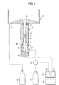
- a measurement cell 1 has a cylindrical shape in which an opening is formed at each of the upper and lower ends.
- a through hole is formed in the peripheral wall in the vicinity of the lower end and functions as a substrate solution inlet 2.
- the interior of the measurement cell 1 is composed, in the sequence starting from the lower end, of a portion filled with fresh substrate solution 3 of a large diameter, a pH electrode body accommodating portion 5 of a small diameter, and a thin-tube type solid phase insertion portion 7 which is slightly larger in diameter than the pH electrode body accommodating portion 5.
- a pH electrode 30 is inserted into the whole of the interior of the measurement cell.
- a pH electrode body portion 4 of the pH electrode 30 is accommodated in the portion filled with fresh substrate solution 3 and the pH electrode body accommodating portion 5.
- a pH electrode sensing portion 6 of the pH electrode 30 is accommodated in the thin-tube type solid phase insertion portion 7.
- a pH electrode connector 13 is attached to the basal end of the pH electrode 30. The opening of the lower end of the measurement cell 1 is hermetically sealed by the pH electrode connector 13.
- a reference electrode 12 is attached to the pH electrode connector 13 so as to be accommodated in the portion filled with fresh substrate solution 3.
- An annular groove is formed in the peripheral wall of the thin-tube type solid phase insertion portion 7 of the measurement cell 1.
- An O-ring 8 is fitted into the groove. The O-ring 8 is used for, when a thin-tube type solid phase 19 shown in Fig. 5 is inserted into the thin-tube type solid phase insertion portion 7, hermetically sealing a gap between the thin-tube type solid phase 19 and the peripheral wall of the thin-tube type solid phase insertion portion 7.
- the upper end opening of the measurement cell 1 serves as a thin-tube type solid phase insertion port 9 through which the thin-tube type solid phase 19 shown in Fig. 5 is to be inserted into the thin-tube type solid phase insertion portion 7.
- the outside of the upper end of the measurement cell 1 is a substrate solution overflow portion 10 from which an overflowing substrate solution is recovered.
- the substrate solution which is recovered from the substrate solution overflow portion 10 reaches a waste solution vessel 16 via a substrate solution outlet 11.
- the supply of the substrate solution to the measurement cell 1 is performed by supplying a substrate solution contained in a substrate solution vessel 15, by a solution feed pump 14 via the substrate solution inlet 2.
- An electric circuit unit 17 has a data processing function which performs calculations on the basis of electric signals from the pH electrode 30 and the reference electrode 12, to calculate a pH-change and supplies the calculation result to a display unit, and a drive controlling function which controls the driving of the solution feed pump 14.
- the display unit 18 performs a display corresponding to the signal supplied from the electric circuit unit 17.
- a monoclonal antibody to urease secreted by Helicobacter pylori serving as a receptor is previously fixed to the inner and outer walls of the thin-tube type solid phase 19.
- the operator then soaks one end portion of the thin-tube type solid phase 19 in a sample solution for a given time period and takes out it from the sample solution.
- the one end portion is accommodated in the thin-tube type solid phase insertion portion 7 through the thin-tube type solid phase insertion port 9 of the measurement cell 1.
- a so-called coupling state in which the pH electrode sensing portion 6 is inserted into the thin-tube type solid phase 19 is established.
- the operator instructs the electric circuit unit 17 to start the operation, so that the solution feed pump 14 is driven and the substrate solution is supplied to the interior of the thin-tube type solid phase 19 to wash the interior.
- the solution feed pump 14 is stopped and there occurs a pH-change in the substrate solution in the thin-tube type solid phase 19.
- the electric circuit unit 17 detects the change on the basis of the output voltage of the pH electrode 30, and the value of the detected change is displayed on the display unit 18.
- the present invention provides a measuring apparatus for either a material or an organism which can induce a pH change in a substrate solution, said measuring apparatus comprising:
- the present invention further provides a method for measuring either a material or an organism which can induce a pH change in a substrate solution, said method comprising the steps of:
- the operator soaks one end of the thin-tube type solid phase in the sample solution.
- the thin-tube type solid phase is then held in the cell by the holding means.
- a pH-change occurs in the substrate solution in the thin-tube type solid phase.
- the substrate solution in the thin-tube type solid phase is moved to the sensing portion of the pH electrode by the substrate solution moving means.
- the pH electrode detects the pH of the substrate solution at this timing.
- a volume of a space between a basal end of said sensing portion of said pH electrode and said one end of said thin-tube type solid phase excluding a volume occupied by said sensing portion is preferably 10 microliters or less.
- said receptor may be an antibody to urease secreted by Helicobacter pylori
- said substrate solution is a solution containing urea. According to the apparatus, it is possible to measure the concentration of urease secreted by Helicobacter pylori.
- said pH electrode may be a pH sensitive field effect transistor.
- This apparatus is small in size. A measurement using this apparatus can be performed with a high sensitivity and a high spewed.
- said thin-tube type solid phase may have a fibrous material in which the receptor specific to the material or the organism immobilized to the interior of said thin tube.
- the specific surface area of the solid phase can be increased as compared with the case using a simple thin tube, whereby the detection limit for the material or the organism to be measured can be lowered.
- one end of a thin-tube type solid phase comprising a thin tube is soaked in a sample solution and then taken out from said sample solution, a receptor specific for the material or the organism being immobilized at least to an interior of said thin tube; said one end of said thin-tube type solid phase is disposed in a substrate solution and in the vicinity of a sensing portion of a pH electrode detecting a pH-change of a solution, said substrate solution containing a substrate for the material or the organism; and said substrate solution in said thin-tube type solid phase after a reaction of induction of a pH-change is moved to said sensing portion of said pH electrode.
- the pH electrode outputs a result which is identical with that measured by inserting a sensing portion into a thin-tube type solid phase.
- Fig. 1 shows the configuration of the apparatus
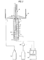
- Fig. 2 shows a state in which the apparatus is used.
- the apparatus is different from that of the prior art shown in Figs. 4 and 5 in that a pH electrode sensing portion accommodating portion 21 is disposed between the pH electrode body accommodating portion 5 and thin-tube type solid phase insertion portion 7 in the measurement cell 1 of the prior art apparatus.
- the pH electrode sensing portion 6 is accommodated in the pH electrode sensing portion accommodating portion.
- the solution feed pump 14 supplies the substrate solution to the measurement cell 1 in a one-way manner.
- a solution feed pump 40 operates also so as to suck the substrate solution in the measurement cell 1 although the sucking amount is very smaller than the supplying amount of the substrate solution.
- an electric circuit unit 70 is configured in a slightly different manner from the electric circuit unit 17 of the prior art apparatus, so that the solution feed pump 40 can rotate in both the forward and rearward directions.
- the other portions are configured in the same manner as those of the prior art apparatus and hence designated by the same reference numerals. Hereinafter, the main portions will be described in detail.
- the operator soaks one end portion of the thin-tube type solid phase 19 in the sample solution so that the sample solution is sucked into the thin tube.
- the sample solution is naturally sucked by the capillary phenomenon into the thin tube without intentionally performing a sucking operation.
- the material or the organism which can induce a pH-change of a substrate solution, which is in the sample solution, and which is to be measured is captured by the receptor in the thin tube.
- the operator inserts the one end portion of the thin-tube type solid phase 19 which has undergone the above-mentioned operation, into the thin-tube type solid phase insertion portion 7 through the thin-tube type solid phase insertion port 9 of the measurement cell 1.
- the state at this time is shown in Fig. 2.
- the operator instructs the electric circuit unit 70 to start the operation, so that the solution feed pump 40 is driven and the substrate solution accommodated in substrate solution vessel 15 is supplied to the measurement cell 1, thereby sufficiently washing the interior of the thin-tube type solid phase 19.
- the data processing unit 71 reads the output voltage V0 of the pH electrode 30 at the timing when the washing operation is ended, and stores the output voltage.
- the drive controlling unit 72 then stops the solution feed pump 40 for a predetermined time period. During this period, in the thin-tube type solid phase 19, the reaction between the substrate and the captured material or organism which can induce a pH-change of a substrate solution proceeds. As a result of the reaction, the substrate in the substrate solution is decomposed and the pH of the substrate solution in the thin-tube type solid phase 19 becomes changed.
- the drive controlling unit 72 controls the solution feed pump 40 to slightly rotate in the rearward direction so that the substrate solution reversely flows, and then stops the solution feed pump 40.
- the substrate solution in the thin-tube type solid phase 19 which solution has undergone the reaction reaches the pH electrode sensing portion accommodating portion 21.
- the output voltage of the pH electrode 30 is varied.
- the data processing unit 71 reads and stores the output voltage V of the pH electrode 30. This voltage corresponds to the pH of the substrate solution after the reaction.
- the data processing unit 71 calculates the following expression by using the stored data V0 and V to obtain a pH-change of the substrate solution due to the material or the organism which can induce a pH-change of a substrate solution.
- the obtained value is displayed on the display unit 18.
- ⁇ pH (V - V0)/S where S is the sensitivity of the pH electrode 30.
- the value of ⁇ pH is increased (in the case of minus, decreased) as the measuring object, or the concentration of the material or the organism which can induce a pH-change of substrate solution, in the substrate solution is increased.
- the operator takes out the thin-tube type solid phase 19 from the measurement cell 1 and instructs the drive controlling unit 72 to rotate the solution feed pump 40 in the forward rotation.
- the interior of the measurement cell 1 is washed by the substrate solution.
- the apparatus is fundamentally configured in the same manner as that shown in Fig. 1.
- a pH-FET which is disclosed in Japanese patent publication (Kokoku) No. HEI4-51786 and in which a pH sensitive membrane is made of tantalum oxide was used as the pH electrode 30.
- the pH electrode has the following dimensions, i.e., the width of 0.45 mm, the thickness of 0.2 mm, and the length of 5.5 mm.
- a tip end portion of 0.8 mm in the pH electrode serves as the pH electrode sensing portion 6.
- the pH electrode had a pH sensitivity of 58 mV/pH at 25°C, and a mutual conductance of 350 microsiemens.
- a silver wire the surface of which is chlorinated was used as the reference electrode 12.
- the pH electrode 30 was positioned so that the pH electrode sensing portion 6 was accommodated in the accommodating portion 21 (having an inner diameter of 0.7 mm), and the reference electrode was 12 was accommodated in the portion filled with fresh substrate solution 3. These electrodes were fixed to the pH electrode connector 13. At this time, the pH electrode 30 was positioned so that the distance between the upper end of the pH electrode 30 and the lower end of the thin-tube type solid phase 19 is in the range of about 0.1 to 2.0 mm.
- the pH electrode 30 (pH-FET) was operated at the drain voltage of 3 volts and the drain current of 7 ⁇ A and with connecting the electrode to a constant current circuit.
- the source potential of the pH electrode 30 relative to the reference electrode 12 was measured as the output signal of the pH electrode 30 (pH-FET).
- a tube pump which is driven by a stepping motor was used as the solution feed pump 40.
- the electric circuit unit 70 comprises a digital computer which is provided with functions of controlling the solution feed pump 40, and performing a calculation process on the basis of the output signal of the pH electrode 30. These functions correspond to the drive controlling unit 72 and the data processing unit 71 shown in Fig. 1, respectively.
- the receptor used was a monoclonal antibody to urease secreted by Helicobacter pylori (see K. Nagata, T. Mizuta, Y. Tonokatsu et al., Infection and Immunity 60, 4826-31 (1992)).
- Twenty thin tubes made of polypropylene (the inner diameter: 0.60 mm, the outer diameter: 1 mm, and the length: 15 mm) were soaked into 1 ml of a PBS solution (pH: 7.4) of 50 ⁇ g/ml of the monoclonal antibody, and allowed to stand at room temperature for 24 hours, thereby immobilizing the antibody to the inner and outer faces of the thin tube.
- the antibody solution was separated by centrifugal separation.
- the thin tubes were soaked in a PBS solution (pH: 7.4) containing 10% of saccharose, 1% of bovine serum albumin, and 0.1% of sodium azide, and allowed to stand at room temperature for 24 hours, whereby a blocking treatment was carried out. Thereafter, the blocking solution was separated by centrifugal separation.
- the thin-tube type solid phases were air-dried at room temperature. The thin-tube type solid phases were then accommodated in a hermetically sealed container and kept at 4°C.
- Urease secreted by Helicobacter pylori was diluted with a PBS solution (pH: 7.4) to prepare plural kinds of sample solutions of different predetermined concentrations.
- the thin-tube type solid phases 19 which were prepared in B above were soaked into the sample solutions of 10 ⁇ l, respectively and allowed to stand at room temperature for 1 hour.
- an aqueous solution containing 2 mM of urea, 10 mM of ammonium chloride, and 154 mM of sodium chloride was used as the substrate solution.
- the operator instructs the electric circuit unit 70 to start the operation. While supplying the substrate solution at a flow rate of 3 ml/min. to the measurement cell 1 by the solution feed pump 40, the operator inserts the thin-tube type solid phases 19 taken out from one of the sample solutions, into the thin-tube type solid phase insertion portion 7 of the measurement cell 1. The supply of the substrate solution is conducted for 60 seconds after the start, and the interior of the thin-tube type solid phase 19 is washed. After the time period of 60 seconds elapses, the drive controlling unit 72 stops the solution feed pump 40. At the same time, the data processing unit 71 reads and stores the output voltage V0 of the pH electrode 30 at this timing.
- the drive controlling unit 72 keeps the solution feed pump 40 stopping for 55 seconds so that the decomposition reaction of the substrate proceeds in the thin-tube type solid phase 19.
- the solution feed pump 40 is rotated by 2 steps in the rearward direction and then stopped.
- the step number in the rearward direction corresponds to the reverse flow of about 1 ⁇ l of the substrate solution in the thin-tube type solid phase 19.
- the data processing unit 71 reads and stores the source potential V of the pH electrode 30 at a timing when a time period of 5 seconds elapses after the rotation in the rearward direction, and calculates above expression (1) on the basis of this potential V and the previously stored potential V0, to obtain ⁇ pH.
- the obtained ⁇ pH is displayed on the display unit 18.
- the operator takes out the thin-tube type solid phase 19 from the measurement cell 1, and then instructs the data processing unit 71 to rotate the solution feed pump 40 in the forward direction so that the substrate solution is supplied at a flow rate of 3 ml/min. to the measurement cell 1 for 15 seconds, thereby washing the interior of the measurement cell 1.
- the apparatus was configured in the same manner as that of A of test example 1.
- Thin-tube type solid phases wherein glass wool to which an antibody was immobilized was filled into a thin tube were prepared in the following manner.
- the apparatus was configured by using parts which are identical with those used in A of test example 1 except that the position of the pH electrode 30 was slightly upward shifted so that the pH electrode sensing portion 6 was accommodated in the thin-tube type solid phase insertion portion 7.
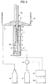
- the thin-tube type solid phase was reacted with the sample solution for 1 hour, the thin-tube type solid phase was inserted into the measurement cell while suppling the substrate solution, and the washing operation was conducted for 60 seconds. Thereafter, V0 was read. Next, the solution feed pump was stopped for 55 seconds, and the output V of the pH electrode at a timing when a time period of 55 seconds elapsed after the beginning of the stop operation was read. The thin-tube type solid phase was then taken out from the measurement cell, and the washing operation was conducted for 15 seconds. Then, ⁇ pH was calculated in accordance with expression (1) by using thus measured V0 and V. The measurement results are shown by void circles in Fig. 3.
- the signal strength in the measurement results according to the invention is substantially equal to those obtained in the coupling of the prior art.
- the strength of the detection signal can be largely increased by using a thin-tube type solid phase having a larger specific surface area, such as the thin-tube type solid phase wherein a glass wool solid phase, which has been physically impossible to be used in the prior art, is filled.
- a material or an organism which can induce a pH-change of a substrate solution can be measured with a high sensitivity and a high speed and without the fear of breaking or contaminating the pH electrode.
- the substrate solution in the thin-tube type solid phase can reach the sensing portion of the pH electrode without being substantially diluted, and the measurement can be conducted with high accuracy. Furthermore, the invention attains an effect that the amount of the solution to be moved can be reduced, the volume of the whole of the cell can be reduced, and the required amount of the sample solution can be made smaller.
- the measurement of the concentration of urease secreted by Helicobacter pylori can be performed with a high sensitivity and a high speed and without the fear of breaking or contaminating the pH electrode.
- the apparatus of the invention is small in size and has an excellent responsibility and a high sensitivity.
- the specific surface area of the thin-tube type solid phase can be increased and the detection limit can be lowered.
- a material or an organism which can induce a pH-change of a substrate solution can be measured with a high sensitivity and a high speed and without the fear of breaking or contaminating the pH electrode.
Landscapes
- Health & Medical Sciences (AREA)
- Life Sciences & Earth Sciences (AREA)
- Immunology (AREA)
- Chemical & Material Sciences (AREA)
- Molecular Biology (AREA)
- Engineering & Computer Science (AREA)
- Analytical Chemistry (AREA)
- Pathology (AREA)
- Hematology (AREA)
- General Physics & Mathematics (AREA)
- Urology & Nephrology (AREA)
- General Health & Medical Sciences (AREA)
- Biochemistry (AREA)
- Biomedical Technology (AREA)
- Physics & Mathematics (AREA)
- Medicinal Chemistry (AREA)
- Food Science & Technology (AREA)
- Biotechnology (AREA)
- Cell Biology (AREA)
- Microbiology (AREA)
- Chemical Kinetics & Catalysis (AREA)
- Electrochemistry (AREA)
- Apparatus Associated With Microorganisms And Enzymes (AREA)
Claims (7)
- Messvorrichtung für ein Material oder einen Organismus, das/der eine pH-Änderung in einer Substratlösung auslösen kann, wobei die Messvorrichtung umfasst:eine Dünnröhren-Festphase, die eine Dünnröhre und einen für das Material oder den Organismus spezifischen Rezeptor enthält, der wenigstens an einer Innenseite der Dünnröhre immobilisiert ist,eine Messzelle, die eine Substratlösung aufnimmt, die ein Substrat für das Material bzw. den Organismus enthält,eine Dünnröhren-Festphasen-Halteeinrichtung, die wenigstens ein Ende der Dünnröhren-Festphase in einem Dünnröhren-Festphasen-Einführabschnitt in der Messzelle aufnimmt,eine pH-Elektrode, die einen Erfassungsabschnitt aufweist und eine pH-Änderung der Substratlösung erfasst, wobei die pH-Elektrode in der Nähe des einen Endes der Dünnröhren-Festphase angeordnet ist, die in der Zelle gehalten wird, und der pH-Elektroden-Ertassungsabschnitt sich außerhalb des Dünnröhren-Festphasen-Einführabschnitts befindet, undeine Substratlösungs-Bewegungseinrichtung zum Bewegen der Substratlösung in der Dünnröhren-Festphase, die in der Messzelle gehalten wird, auf den Erfassungsabschnitt zu.
- Messvorrichtung nach Anspruch 1, wobei in der Messzelle ein Raumvolumen zwischen einem unteren Ende des Erfassungsabschnitts der pH-Elektrode und dem einen Ende der Dünnröhren-Festphase ausschließlich eines Volumens, das durch den Erfassungsabschnitt eingenommen wird, 10 Mikroliter oder weniger beträgt.
- Messvorrichtung nach Anspruch 1, wobei der Rezeptor ein Antikörper für Urease ist, die von Helicobacter pylori ausgeschieden wird, und die Substratlösung eine Lösung ist, die Harnstoff enthält.
- Messvorrichtung nach Anspruch 1, wobei die pH-Elektrode ein pH-empfindlicher Feldeffekttransistor ist.
- Messvorrichtung nach Anspruch 1, wobei die Dünnröhren-Festphase ein Fasermaterial aufweist, in dem der für das Material bzw. den Organismus spezifische Rezeptor an der Innenseite der Dünnröhre immobilisiert ist.
- Messvorrichtung nach Anspruch 1, wobei ein Zwischenraum zwischen einer vorderen Endfläche der pH-Elektrode und einer Fläche der Dünnröhren-Festphase ausgebildet ist, die der vorderen Endfläche gegenüberliegt.
- Verfahren zum Messen eines Materials oder eines Organismus, das/der eine pH-Änderung in einer Substratlösung auslösen kann, wobei das Verfahren die folgenden Schritte umfasst:Eintauchen eines Endes einer Dünnröhren-Festphase in eine Probenlösung und Entnehmen aus der Probenlösung, wobei die Dünnröhren-Festphase einen für das Material bzw. den Organismus spezifischen Rezeptor enthält, der wenigstens an einer Innenseite einer Dünnröhre immobilisiert ist,Anordnen des einen Endes der Dünnröhren-Festphase, so dass es in einem Dünnröhren-Festphasen-Einführabschnitt einer Messzelle aufgenommen und gehalten wird, in einer Substratlösung und in der Nähe eines Erfassungsabschnitts einer pH-Elektrode, die eine pH-Änderung der Lösung erfasst, wobei sich der pH-Elektroden-Erfassungsabschnitt außerhalb des Dünnröhren-Festphasen-Einführabschnitts befindet und die Substratlösung ein Substrat für das Material bzw. den Organismus enthält, undBewegen der Substratlösung in der Dünnröhren-Festphase nach einer Reaktion des Auslösens einer pH-Änderung zu dem Erfassungsabschnitt der pH-Elektrode.
Applications Claiming Priority (3)
| Application Number | Priority Date | Filing Date | Title |
|---|---|---|---|
| JP147444/97 | 1997-06-05 | ||
| JP14744497 | 1997-06-05 | ||
| JP14744497A JP3612675B2 (ja) | 1997-06-05 | 1997-06-05 | pH変化誘因性物質または生物体の測定装置及び測定方法 |
Publications (2)
| Publication Number | Publication Date |
|---|---|
| EP0882971A1 EP0882971A1 (de) | 1998-12-09 |
| EP0882971B1 true EP0882971B1 (de) | 2004-11-10 |
Family
ID=15430490
Family Applications (1)
| Application Number | Title | Priority Date | Filing Date |
|---|---|---|---|
| EP98110209A Expired - Lifetime EP0882971B1 (de) | 1997-06-05 | 1998-06-04 | Messvorrichtung und Verfahren für Material für einen Organismus, der eine pH-Änderung einer Substratlösung hervorrufen kann |
Country Status (4)
| Country | Link |
|---|---|
| US (1) | US6379910B1 (de) |
| EP (1) | EP0882971B1 (de) |
| JP (1) | JP3612675B2 (de) |
| DE (1) | DE69827433T2 (de) |
Families Citing this family (5)
| Publication number | Priority date | Publication date | Assignee | Title |
|---|---|---|---|---|
| DE10004583C2 (de) * | 2000-02-02 | 2002-04-25 | Testo Gmbh & Co | Messvorrichtung mit Einstechelektrode |
| US7141369B2 (en) * | 2002-04-25 | 2006-11-28 | Semibio Technology, Inc. | Measuring cellular metabolism of immobilized cells |
| US7009694B2 (en) * | 2004-05-28 | 2006-03-07 | International Business Machines Corporation | Indirect switching and sensing of phase change memory cells |
| JP4625946B2 (ja) * | 2004-11-02 | 2011-02-02 | 国立大学法人 岡山大学 | pH測定装置及びpH測定方法 |
| KR101174360B1 (ko) | 2010-11-30 | 2012-08-21 | 한국전기연구원 | pH를 측정하기 위한 장치 및 그 방법 |
Family Cites Families (17)
| Publication number | Priority date | Publication date | Assignee | Title |
|---|---|---|---|---|
| US4398554A (en) * | 1981-04-09 | 1983-08-16 | Nihon Den-Netsu Keiki Co., Ltd. | Flux control device |
| US4659678A (en) * | 1982-09-29 | 1987-04-21 | Serono Diagnostics Limited | Immunoassay of antigens |
| US4585623A (en) * | 1984-02-27 | 1986-04-29 | Allelix Inc. | Device for performing quantitative chemical and immunochemical assays |
| GB8405691D0 (en) * | 1984-03-05 | 1984-04-11 | Serono Diagnostics Ltd | Methods of assay |
| GB8406955D0 (en) | 1984-03-16 | 1984-04-18 | Serono Diagnostics Ltd | Assay |
| JPS60231156A (ja) * | 1984-04-30 | 1985-11-16 | Kuraray Co Ltd | 液絡式の比較電極 |
| AU588245B2 (en) * | 1984-06-13 | 1989-09-14 | Inverness Medical Switzerland Gmbh | Devices for use in chemical test procedures |
| US4690801A (en) * | 1986-06-03 | 1987-09-01 | Allelix Inc. | Device for performing enzyme immunoassays |
| US5158868A (en) * | 1987-07-17 | 1992-10-27 | Iniziative Marittime 1991, S.R.L. | Method of sample analysis |
| ZA889546B (en) | 1987-12-24 | 1990-08-29 | Igen Inc | Chemical sensors employing catalytic antibodies |
| JP2591641B2 (ja) | 1988-02-19 | 1997-03-19 | 株式会社クラレ | 微量アナライト物質の測定方法及び測定装置 |
| US5120648A (en) * | 1988-05-26 | 1992-06-09 | Lim Technology Laboratories, Inc. | Chemical analyzer using rf radiation attenuation measurements |
| US5133937A (en) * | 1989-06-01 | 1992-07-28 | Iniziative Marittime, 1991 S.R.L. | Analysis system having a removable reaction cartridge and temperature control |
| US5253539A (en) * | 1991-07-09 | 1993-10-19 | Iniziative Marittime 1991, S.R.L. | Analyzer system |
| KR940010562B1 (ko) * | 1991-09-06 | 1994-10-24 | 손병기 | Ta_2O_5수소이온 감지막을 갖는 감이온 전계효과 트랜지스터의 제조방법 |
| JP2634374B2 (ja) | 1993-11-01 | 1997-07-23 | 株式会社バイオセンサー研究所 | 微量アナライト物質または生物体の測定装置 |
| JP2691510B2 (ja) * | 1994-06-02 | 1997-12-17 | 株式会社バイオセンサー研究所 | 酵素の測定装置 |
-
1997
- 1997-06-05 JP JP14744497A patent/JP3612675B2/ja not_active Expired - Fee Related
-
1998
- 1998-06-04 DE DE69827433T patent/DE69827433T2/de not_active Expired - Fee Related
- 1998-06-04 US US09/090,410 patent/US6379910B1/en not_active Expired - Fee Related
- 1998-06-04 EP EP98110209A patent/EP0882971B1/de not_active Expired - Lifetime
Also Published As
| Publication number | Publication date |
|---|---|
| DE69827433T2 (de) | 2005-03-24 |
| DE69827433D1 (de) | 2004-12-16 |
| JP3612675B2 (ja) | 2005-01-19 |
| US6379910B1 (en) | 2002-04-30 |
| EP0882971A1 (de) | 1998-12-09 |
| JPH10332634A (ja) | 1998-12-18 |
Similar Documents
| Publication | Publication Date | Title |
|---|---|---|
| US6100094A (en) | Method for sucking/determining liquid and pipetting device driven and controlled according to method | |
| RU2238548C2 (ru) | Способ измерения концентрации анализируемого вещества (варианты), измерительный прибор для измерения концентрации анализируемого вещества | |
| US7897409B2 (en) | Chemical analyzer, method for dispensing and dilution cup | |
| US8399259B2 (en) | Measuring device, measuring apparatus and method of measuring | |
| JPS62119451A (ja) | 分析装置 | |
| JPH04357449A (ja) | バイオセンサおよびバイオセンサ測定装置 | |
| EP0882971B1 (de) | Messvorrichtung und Verfahren für Material für einen Organismus, der eine pH-Änderung einer Substratlösung hervorrufen kann | |
| JP2630005B2 (ja) | 液体成分測定装置および測定方法 | |
| US4956149A (en) | Biosensor device provided with an agitator | |
| JP2591641B2 (ja) | 微量アナライト物質の測定方法及び測定装置 | |
| JP4184356B2 (ja) | センサ、測定装置および測定方法 | |
| US4619739A (en) | Method and apparatus for measuring halogen ion concentration | |
| US20080105566A1 (en) | Sensor, Measuring Device, And Measuring Method | |
| JP2015087293A (ja) | グリコアルブミンの測定キットおよび測定方法 | |
| Uhlig et al. | Miniaturised ion-selective sensor chip for potassium measurement in a biomedical application | |
| JP2005127974A (ja) | 水素イオン濃度の測定装置および測定方法 | |
| JP2634374B2 (ja) | 微量アナライト物質または生物体の測定装置 | |
| US4434232A (en) | Measuring vessels analysis utilizing fixed enzyme | |
| JPH05126792A (ja) | 濃度測定装置とバイオセンサ及び尿中成分測定方法 | |
| JP3058965B2 (ja) | 溶液成分センサ | |
| JPH11326262A (ja) | バイオセンサ | |
| JPH10262645A (ja) | α−アミラーゼ酵素活性測定用酵素センサー及びα−アミラーゼ酵素活性の測定方法 | |
| JPS58149746A (ja) | シリンジ型生体試料分析装置 | |
| JPH0524212Y2 (de) | ||
| JP2002340898A (ja) | 被検物質の検出方法及び検出装置 |
Legal Events
| Date | Code | Title | Description |
|---|---|---|---|
| PUAI | Public reference made under article 153(3) epc to a published international application that has entered the european phase |
Free format text: ORIGINAL CODE: 0009012 |
|
| AK | Designated contracting states |
Kind code of ref document: A1 Designated state(s): DE FR GB |
|
| AX | Request for extension of the european patent |
Free format text: AL;LT;LV;MK;RO;SI |
|
| 17P | Request for examination filed |
Effective date: 19981228 |
|
| AKX | Designation fees paid |
Free format text: DE FR GB |
|
| 17Q | First examination report despatched |
Effective date: 20021127 |
|
| GRAP | Despatch of communication of intention to grant a patent |
Free format text: ORIGINAL CODE: EPIDOSNIGR1 |
|
| GRAS | Grant fee paid |
Free format text: ORIGINAL CODE: EPIDOSNIGR3 |
|
| GRAA | (expected) grant |
Free format text: ORIGINAL CODE: 0009210 |
|
| AK | Designated contracting states |
Kind code of ref document: B1 Designated state(s): DE FR GB |
|
| REG | Reference to a national code |
Ref country code: GB Ref legal event code: FG4D |
|
| REF | Corresponds to: |
Ref document number: 69827433 Country of ref document: DE Date of ref document: 20041216 Kind code of ref document: P |
|
| PLBE | No opposition filed within time limit |
Free format text: ORIGINAL CODE: 0009261 |
|
| STAA | Information on the status of an ep patent application or granted ep patent |
Free format text: STATUS: NO OPPOSITION FILED WITHIN TIME LIMIT |
|
| ET | Fr: translation filed | ||
| 26N | No opposition filed |
Effective date: 20050811 |
|
| PGFP | Annual fee paid to national office [announced via postgrant information from national office to epo] |
Ref country code: DE Payment date: 20080612 Year of fee payment: 11 |
|
| PGFP | Annual fee paid to national office [announced via postgrant information from national office to epo] |
Ref country code: FR Payment date: 20080617 Year of fee payment: 11 |
|
| PGFP | Annual fee paid to national office [announced via postgrant information from national office to epo] |
Ref country code: GB Payment date: 20080604 Year of fee payment: 11 |
|
| GBPC | Gb: european patent ceased through non-payment of renewal fee |
Effective date: 20090604 |
|
| REG | Reference to a national code |
Ref country code: FR Ref legal event code: ST Effective date: 20100226 |
|
| PG25 | Lapsed in a contracting state [announced via postgrant information from national office to epo] |
Ref country code: FR Free format text: LAPSE BECAUSE OF NON-PAYMENT OF DUE FEES Effective date: 20090630 |
|
| PG25 | Lapsed in a contracting state [announced via postgrant information from national office to epo] |
Ref country code: GB Free format text: LAPSE BECAUSE OF NON-PAYMENT OF DUE FEES Effective date: 20090604 |
|
| PG25 | Lapsed in a contracting state [announced via postgrant information from national office to epo] |
Ref country code: DE Free format text: LAPSE BECAUSE OF NON-PAYMENT OF DUE FEES Effective date: 20100101 |