EP0883326A2 - Transformator für piezoelektrischen Lautsprecher und piezoelektrischer Lautsprecher mit diesem Transformator - Google Patents
Transformator für piezoelektrischen Lautsprecher und piezoelektrischer Lautsprecher mit diesem Transformator Download PDFInfo
- Publication number
- EP0883326A2 EP0883326A2 EP98401302A EP98401302A EP0883326A2 EP 0883326 A2 EP0883326 A2 EP 0883326A2 EP 98401302 A EP98401302 A EP 98401302A EP 98401302 A EP98401302 A EP 98401302A EP 0883326 A2 EP0883326 A2 EP 0883326A2
- Authority
- EP
- European Patent Office
- Prior art keywords
- transformer
- piezoelectric speaker
- secondary winding
- winding
- piezoelectric
- Prior art date
- Legal status (The legal status is an assumption and is not a legal conclusion. Google has not performed a legal analysis and makes no representation as to the accuracy of the status listed.)
- Withdrawn
Links
Images


Classifications
-
- H—ELECTRICITY
- H01—ELECTRIC ELEMENTS
- H01F—MAGNETS; INDUCTANCES; TRANSFORMERS; SELECTION OF MATERIALS FOR THEIR MAGNETIC PROPERTIES
- H01F30/00—Fixed transformers not covered by group H01F19/00
- H01F30/06—Fixed transformers not covered by group H01F19/00 characterised by the structure
- H01F30/10—Single-phase transformers
-
- H—ELECTRICITY
- H04—ELECTRIC COMMUNICATION TECHNIQUE
- H04R—LOUDSPEAKERS, MICROPHONES, GRAMOPHONE PICK-UPS OR LIKE ACOUSTIC ELECTROMECHANICAL TRANSDUCERS; ELECTRIC HEARING AIDS; PUBLIC ADDRESS SYSTEMS
- H04R17/00—Piezoelectric transducers; Electrostrictive transducers
-
- H—ELECTRICITY
- H04—ELECTRIC COMMUNICATION TECHNIQUE
- H04R—LOUDSPEAKERS, MICROPHONES, GRAMOPHONE PICK-UPS OR LIKE ACOUSTIC ELECTROMECHANICAL TRANSDUCERS; ELECTRIC HEARING AIDS; PUBLIC ADDRESS SYSTEMS
- H04R3/00—Circuits for transducers
- H04R3/04—Circuits for transducers for correcting frequency response
Definitions
- the present invention relates to a transformer for a piezoelectric speaker which is optimum for driving a piezoelectric speaker, and to a piezoelectric speaker operative with the transformer.
- a transformer 1 comprises a toroidal magnetic core 2 in the form of a square frame, a primary winding 3 wound around the lower part of the magnetic core in the drawing and a secondary winding 4 wound around the upper part of the magnetic core 2 in the drawing apart from the primary winding 3.
- the primary winding 3 is connected to an input terminal 5 that connects to an amplifier (not shown) for driving a speaker, and the secondary winding 4 is connected to a sounding body 6 constituted by a piezoelectric body to form a piezoelectric speaker 7.
- output impedance of an amplifier is substantially 0 ohm
- the frequency characteristics of the transformer connected to the amplifier and the sounding body constituted by a piezoelectric body are not determined simply by the inductance of the secondary winding of the transformer but determined by the inductance of the secondary winding when the primary winding is short-circuited, which is referred to as leakage inductance.
- the leakage inductance depends on the degree of coupling between the primary and secondary windings. For example, the leakage inductance tends to decrease as the degree of coupling between the primary and secondary windings increases.
- the frequency characteristics of the transformer connected to the sounding body are expressed by the curves shown in Fig. 5.
- the frequency at which response represented by the ordinate tends to decrease is referred to as "high frequency cut-off".
- the curve indicated by the broken line represents leakage inductance higher than that represented by the curve indicated by the solid line.
- the sounding body constituted by a piezoelectric body When the sounding body constituted by a piezoelectric body is driven at a predetermined voltage, the sounding body constituted by a piezoelectric body has high impedance at low frequencies and conversely has low impedance at high frequencies because it has capacitive properties. Therefore, the sound pressure characteristics of the sounding body are expressed by the curve shown in Fig. 6. It is assumed here that no transformer is connected to the sounding body.
- the piezoelectric speaker device described as an example of the related art exhibits extreme distortion in its characteristics in a low frequency band because of core loss when the transformer is used from a frequency band as low as 20 Hz.
- a possible means for improving this is to increase the number of turns of the transformer significantly to reduce the influence of the core loss. In this case, however, leakage inductance as described above will increase.
- sounds in a high frequency band can be made more penetrating by decreasing the capacity of the piezoelectric body. In this case, however, a shortage of sounds occurs in a low frequency band and signals input to the piezoelectric body will be converted into sounds at reduced efficiency.
- a transformer for a piezoelectric speaker having a sounding body constituted by a piezoelectric body, comprising a magnetic core, a primary winding, and a secondary winding, wherein the primary winding is connectable to an input terminal for receiving a drive signal for driving the sounding body; the secondary winding is connectable to the sounding body; characterised in that the secondary winding is divided into two parts; and one of the divided secondary windings, primary winding, and the other divided secondary winding are wound around the magnetic core in an overlapping relationship in the order designated.
- the overlapping relationship can increase the contact area between the primary and secondary windings to a value twice or more than the contact area in a conventional transformer, whereupon the degree of coupling between the primary and secondary windings is also increased.
- the transformer when used in a piezoelectric speaker, a sufficient degree of coupling is achieved between the primary and secondary windings even if the number of windings of the transformer is increased, with a consequent increase in leakage inductance.
- the leakage inductance of the piezoelectric speaker is lower than that in conventional speakers. As a result, sufficient sound pressure characteristics can be achieved in both low and high frequency bands.
- the invention also relates to a piezoelectric speaker device comprising :
- Fig. 1 is a sectional view showing a structure of a transformer for a piezoelectric speaker according to an embodiment of the present invention.
- Fig. 2 is a schematic diagram illustrating the connection of a piezoelectric speaker with a transformer to form a piezoelectric speaker system according to the present invention.
- Fig. 3 illustrates frequency characteristics of a transformer for a piezoelectric speaker according to the present invention in conjunction with a sounding body.
- Fig. 4 illustrates a conventional transformer for a piezoelectric speaker.
- Fig. 5 illustrates frequency characteristics of a transformer for a piezoelectric speaker connected to a sounding body.
- Fig. 6 illustrates sound pressure characteristics of a sounding body constituted by a piezoelectric body which is not connected to a transformer for a piezoelectric speaker.
- FIG. 1 shows a transformer for a piezoelectric speaker according to an embodiment of the present invention.
- a transformer 10 for a piezoelectric speaker includes an E-shaped magnetic core 11.
- An inner secondary winding 12a having a number of turns corresponding to approximately one-half of the number of turns of a secondary winding 12 is wound around a shaft portion of the magnetic core 11.
- a primary winding 13 is wound around the shaft portion of the magnetic core 11 over the inner secondary winding 12a.
- an outer secondary winding 12b having a number of turns corresponding to the other half of the number of turns of the secondary winding 12 is wound around the shaft portion of the magnetic core 11 over the primary winding 13.
- An I-shaped core 16 is provided at the open side of the E-shaped magnetic core 11 to complete the transformer 10 as an EI core type transformer.
- the transformer 10 for a piezoelectric speaker has a structure wherein the primary winding 13 is sandwiched by the secondary winding 12.
- the primary winding 13 and secondary winding 12 contact with each other in an area larger than that in a conventional transformer for a piezoelectric speaker and, therefore, the degree of coupling between the primary and secondary windings is also improved.
- Fig. 2 illustrates an implementation of this transformer 10 in a piezoelectric speaker to form a piezoelectric speaker device.
- the piezoelectric speaker device can be made as a self-contained unit comprising the piezoelectric speaker 20 itself and the transformer so connected thereto.
- the unit may also optionally incorporate an audio amplifier for driving the piezoelectric speaker 20 from a signal source, such as a pre-amplifier, tuner or disc player, etc.
- a piezoelectric speaker 20 includes a sounding body 15 constituted by a piezoelectric body.
- the primary winding 13 of the transformer 10 for a piezoelectric speaker is connected to an input terminal 14 that receives the output signal of an amplifier (not shown) for driving the sounding body 15 of the piezoelectric speaker 20.
- the secondary winding 12 is connected to the sounding body 15 of the piezoelectric speaker 20.
- Fig. 2 schematically shows the secondary winding 12 divided into two parts (12a and 12b). Although the inner secondary winding 12a, the primary winding 13 and the outer secondary winding 12b are shown adjacent to each other around the magnetic core 11 in Fig. 2, in practice, the inner secondary winding 12a is wound around the magnetic core 11; the primary winding 13 is wound thereon; and the outer secondary winding 12b is further wound thereon as shown in Fig. 1.
- the sounding body 15 constituted by a piezoelectric body may be, for example, a sounding body including vibrator made piezoelectric ceramic in the form of a hemispherical or spherical shell or a sounding body including a plate vibrator made of piezoelectric ceramic.
- a sounding body including vibrator made piezoelectric ceramic in the form of a hemispherical or spherical shell or a sounding body including a plate vibrator made of piezoelectric ceramic.
- a high degree of coupling is achieved between the primary and secondary windings of the transformer 10 for a piezoelectric speaker to reduce leakage inductance as compared with that in a conventional piezoelectric speaker.
- the piezoelectric speaker 20 has a high frequency cut-off at a high value and can therefore generate sounds over a wide range including low and high frequency bands with a sufficient sound pressure.
- the secondary winding is wound with its number of turns divided into approximately two halves in the above-described embodiment, the division of the number of turns is not limited in this way.
- the number of turns of the secondary winding that form the respective inner and outer windings 12a and 12b can be set to any arbitrary ratio a:b, where a and b respectively designate the number of turns in secondary winding layers 12a and 12b..
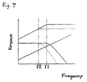
- the frequency characteristics of a transformer for a piezoelectric speaker and a sounding body may result in a curve having a convex peak around a high frequency cut-off f0 or a curve that tends to gradually decrease just before the high frequency cut-off f0. This is attributable to resonance between leakage inductance and the capacity of the piezoelectric body.
- an idealised curve as indicated by the solid line can be approximated by changing the diameters of the primary and secondary windings so as to change the winding resistance.
- a transformer for a piezoelectric speaker has a structure wherein the primary winding is sandwiched by the secondary winding to increase the contact area between the primary and secondary windings as compared with a conventional transformer for a piezoelectric speaker, and to improve the degree of coupling between the primary and secondary windings. Further, even if leakage inductance of the transformer for a piezoelectric speaker is increased by increasing the number of turns of the windings thereof, sufficient sound pressure characteristics can be achieved in both low and high frequency bands because a sufficient degree of coupling is achieved between the primary and secondary windings, and the leakage inductance of the piezoelectric speaker is smaller than that in the conventional ones.
Landscapes
- Engineering & Computer Science (AREA)
- Power Engineering (AREA)
- Physics & Mathematics (AREA)
- Acoustics & Sound (AREA)
- Signal Processing (AREA)
- Circuit For Audible Band Transducer (AREA)
- Piezo-Electric Transducers For Audible Bands (AREA)
Applications Claiming Priority (6)
| Application Number | Priority Date | Filing Date | Title |
|---|---|---|---|
| JP145280/97 | 1997-06-03 | ||
| JP14528097 | 1997-06-03 | ||
| JP14528097 | 1997-06-03 | ||
| JP81334/98 | 1998-03-27 | ||
| JP8133498 | 1998-03-27 | ||
| JP08133498A JP3309798B2 (ja) | 1997-06-03 | 1998-03-27 | 圧電スピーカ用トランス |
Publications (2)
| Publication Number | Publication Date |
|---|---|
| EP0883326A2 true EP0883326A2 (de) | 1998-12-09 |
| EP0883326A3 EP0883326A3 (de) | 2005-07-13 |
Family
ID=26422355
Family Applications (1)
| Application Number | Title | Priority Date | Filing Date |
|---|---|---|---|
| EP98401302A Withdrawn EP0883326A3 (de) | 1997-06-03 | 1998-05-29 | Transformator für piezoelektrischen Lautsprecher und piezoelektrischer Lautsprecher mit diesem Transformator |
Country Status (2)
| Country | Link |
|---|---|
| EP (1) | EP0883326A3 (de) |
| JP (1) | JP3309798B2 (de) |
Cited By (3)
| Publication number | Priority date | Publication date | Assignee | Title |
|---|---|---|---|---|
| US6718040B1 (en) * | 1999-06-18 | 2004-04-06 | Murata Manufacturing Co., Ltd. | Transformer, loudspeaker device, loudspeaker network, and loudspeaker system |
| CN113840217A (zh) * | 2021-07-12 | 2021-12-24 | 天津大学 | 压电mems扬声系统 |
| WO2023283784A1 (zh) * | 2021-07-12 | 2023-01-19 | 天津大学 | 压电mems扬声系统 |
Families Citing this family (1)
| Publication number | Priority date | Publication date | Assignee | Title |
|---|---|---|---|---|
| JP5421845B2 (ja) * | 2010-04-23 | 2014-02-19 | パナソニック株式会社 | 車両盗難警報音駆動回路 |
Family Cites Families (3)
| Publication number | Priority date | Publication date | Assignee | Title |
|---|---|---|---|---|
| JPS5799899A (en) * | 1980-12-12 | 1982-06-21 | Sanyo Electric Co Ltd | Electro-acoustic converter |
| US5696477A (en) * | 1994-05-30 | 1997-12-09 | Tabuchi Electric Co., Ltd. | Transformer |
| JPH0864432A (ja) * | 1994-08-26 | 1996-03-08 | Matsushita Electric Works Ltd | 電磁装置 |
-
1998
- 1998-03-27 JP JP08133498A patent/JP3309798B2/ja not_active Expired - Lifetime
- 1998-05-29 EP EP98401302A patent/EP0883326A3/de not_active Withdrawn
Cited By (3)
| Publication number | Priority date | Publication date | Assignee | Title |
|---|---|---|---|---|
| US6718040B1 (en) * | 1999-06-18 | 2004-04-06 | Murata Manufacturing Co., Ltd. | Transformer, loudspeaker device, loudspeaker network, and loudspeaker system |
| CN113840217A (zh) * | 2021-07-12 | 2021-12-24 | 天津大学 | 压电mems扬声系统 |
| WO2023283784A1 (zh) * | 2021-07-12 | 2023-01-19 | 天津大学 | 压电mems扬声系统 |
Also Published As
| Publication number | Publication date |
|---|---|
| JPH1155783A (ja) | 1999-02-26 |
| EP0883326A3 (de) | 2005-07-13 |
| JP3309798B2 (ja) | 2002-07-29 |
Similar Documents
| Publication | Publication Date | Title |
|---|---|---|
| US7317374B2 (en) | Self-damped inductor | |
| CN104936112B (zh) | 一种双振膜结构的扬声器及驱动方法 | |
| US20020018578A1 (en) | Bending wave loudspeaker | |
| JPH0231599A (ja) | 電気音響変換器およびスピーカ | |
| US5519781A (en) | Self damping speaker matching device and method | |
| WO2004084430A1 (ja) | 電力線搬送用モデム結合回路 | |
| US2007747A (en) | Acoustic apparatus | |
| US2727949A (en) | Loudspeaker | |
| CN108566596A (zh) | 音圈绕制方法及音圈、设有该音圈的发声器 | |
| EP0883326A2 (de) | Transformator für piezoelektrischen Lautsprecher und piezoelektrischer Lautsprecher mit diesem Transformator | |
| US5373563A (en) | Self damping speaker matching device | |
| JP4227740B2 (ja) | 低歪率インダクタンス素子および受動回路装置 | |
| JPH0332200A (ja) | 磁気歪バイメタルストリップを用いた球面ダイヤフラム無指向性スピーカ | |
| US6718040B1 (en) | Transformer, loudspeaker device, loudspeaker network, and loudspeaker system | |
| US20250150762A1 (en) | Transducer devices, core modules, and electronic devices | |
| JPS61263105A (ja) | 複合形コモンモ−ドチヨ−クコイル | |
| EP0761074B1 (de) | Verfahren und vorrichtung zur selbstdämpfenden lautsprecheranpassung | |
| JPS5930487Y2 (ja) | 3巻線トランス | |
| JPS60171900A (ja) | スピ−カ | |
| US20040005074A1 (en) | Hi-fi tweeter | |
| JPS60102709A (ja) | インピ−ダンス変換トランス | |
| JPS585100A (ja) | 圧電型スピ−カの駆動方法 | |
| JPS6311819Y2 (de) | ||
| JP2003100518A (ja) | 整合器 | |
| JPS58159203A (ja) | 磁気録画再生装置 |
Legal Events
| Date | Code | Title | Description |
|---|---|---|---|
| PUAI | Public reference made under article 153(3) epc to a published international application that has entered the european phase |
Free format text: ORIGINAL CODE: 0009012 |
|
| AK | Designated contracting states |
Kind code of ref document: A2 Designated state(s): AT BE CH CY DE DK ES FI FR GB GR IE IT LI LU MC NL PT SE |
|
| AX | Request for extension of the european patent |
Free format text: AL;LT;LV;MK;RO;SI |
|
| PUAL | Search report despatched |
Free format text: ORIGINAL CODE: 0009013 |
|
| AK | Designated contracting states |
Kind code of ref document: A3 Designated state(s): AT BE CH CY DE DK ES FI FR GB GR IE IT LI LU MC NL PT SE |
|
| AX | Request for extension of the european patent |
Extension state: AL LT LV MK RO SI |
|
| RIC1 | Information provided on ipc code assigned before grant |
Ipc: 7H 01F 19/02 B Ipc: 7H 01F 1/00 B Ipc: 7H 04R 17/00 A |
|
| 17P | Request for examination filed |
Effective date: 20051219 |
|
| AKX | Designation fees paid |
Designated state(s): DE FR GB |
|
| GRAP | Despatch of communication of intention to grant a patent |
Free format text: ORIGINAL CODE: EPIDOSNIGR1 |
|
| RAP1 | Party data changed (applicant data changed or rights of an application transferred) |
Owner name: MURATA MANUFACTURING CO., LTD. |
|
| STAA | Information on the status of an ep patent application or granted ep patent |
Free format text: STATUS: THE APPLICATION IS DEEMED TO BE WITHDRAWN |
|
| 18D | Application deemed to be withdrawn |
Effective date: 20071218 |