EP0884430A2 - Konstruktion einer Glasbaustein-Wand und Verfahren und Vorrichtung zu ihrer Herstellung - Google Patents
Konstruktion einer Glasbaustein-Wand und Verfahren und Vorrichtung zu ihrer Herstellung Download PDFInfo
- Publication number
- EP0884430A2 EP0884430A2 EP98110257A EP98110257A EP0884430A2 EP 0884430 A2 EP0884430 A2 EP 0884430A2 EP 98110257 A EP98110257 A EP 98110257A EP 98110257 A EP98110257 A EP 98110257A EP 0884430 A2 EP0884430 A2 EP 0884430A2
- Authority
- EP
- European Patent Office
- Prior art keywords
- sealant
- blocks
- seams
- feed tubes
- glass blocks
- Prior art date
- Legal status (The legal status is an assumption and is not a legal conclusion. Google has not performed a legal analysis and makes no representation as to the accuracy of the status listed.)
- Withdrawn
Links
Images


Classifications
-
- E—FIXED CONSTRUCTIONS
- E04—BUILDING
- E04C—STRUCTURAL ELEMENTS; BUILDING MATERIALS
- E04C2/00—Building elements of relatively thin form for the construction of parts of buildings, e.g. sheet materials, slabs, or panels
- E04C2/54—Slab-like translucent elements
- E04C2/546—Slab-like translucent elements made of glass bricks
Definitions
- This invention relates to panels of glass blocks and to devices and methods used in constructing such panels. More particularly, the invention relates to the construction of prefabricated glass block walls without the use of integral spacers or mortar.
- glass block walls or panels In the construction of glass block walls or panels, a significant level of skill is required to properly space and align the blocks with respect to each other. Glass block walls are typically assembled on-site by a mason, much in the same way as brick walls are assembled, with mortar spread on exposed edges of the blocks and set into place. However, glass blocks are normally placed and aligned directly above each other, without overlapping as in the construction of brick walls. When assembling glass block panels, it is essential that rather precise spatial relationships between the glass blocks be maintained in order to provide a more structurally sound and aesthetically pleasing panel.
- Mortarless glass block panels typically include the use of integral spacers interposed between the blocks. Spacers add the benefit of properly aligning the blocks without the necessity of a skilled mason.
- An adhesive is then applied to the spacers and adjacent blocks to bond and secure the panel.
- a clear silicone adhesive is used to caulk in the joints and the outer interfaces of the blocks. Silicone is known to be particularly useful in that it bonds well with glass, yet provides enough flexibility to avoid the cracking problem associated with the use of mortar.
- a method for assembling at least two glass blocks together includes the step of providing a spacing rack for positioning glass blocks in proper spaced alignment such that upper and lower seams are formed between upper and lower interfaces of adjacent blocks and a joint cavity is defined between the seams.
- the glass blocks are positioned on the spacing rack.
- a sealant applying means is inserted into the joint cavity.
- a sealant is simultaneously dispensed into the upper and lower seams through the sealant applying means.
- the sealant is simultaneously compressed into the upper and lower seams as the sealant is dispensed.
- An apparatus for assembling at least two glass blocks together includes a spacing rack for positioning glass blocks in proper spaced alignment, such that upper and lower seams are formed between upper and lower interfaces of adjacent blocks and a joint cavity is defined between the seams.
- the apparatus also includes sealant applying means for dispensing a sealant simultaneously into the upper and lower seams, means for inserting into the joint cavity the sealant applying means, and means for compressing the sealant into the upper and lower seams simultaneously as the sealant is dispensed from the sealant applying means.
- a tool for internally applying sealant into first and second seams formed between adjacent blocks includes a pair of elongated feed tubes having proximal and distal ends and opposing surfaces.
- the proximal ends include an opening for receiving the sealant.
- the feed tubes include an aperture disposed on the opposing surfaces proximate to the distal ends for simultaneously dispensing sealant into the upper and lower seams of adjacent glass blocks and a compacting abutment means for simultaneously compressing the sealant into the upper and lower seams of adjacent glass blocks as the sealant is released from the apertures.
- the feed tubes are secured by at least one rigid cross member fixedly secured and perpendicular to the longitudinal axis of the feed tubes such that when the distal ends of the feed tubes are inserted into the joint cavity, a sufficient tension is created in the compacting abutment means to compress the sealant into the upper and lower seams.
- a prefabricated glass block panel assembly includes a plurality of glass blocks.
- the glass blocks include a generally rectangular configuration with vertical and horizontal end walls and a pair of side walls. The side walls and the end walls form edge portions therebetween.
- the glass blocks are positioned in abutting relation to one another such that seams are formed between edge portions.
- the seams are filled with an adhesive which secure the blocks to one another.
- a tool for internally applying sealant into a seam formed between adjacent glass blocks includes a feed tube having a first member, a flared second member, and a third member.
- the first member and the third member are substantially parallel and are connected by the flared second member such that the third member abuts the seam formed between adjacent blocks when the tool is in use.
- the first member includes an opening for receiving sealant.
- the third member includes an aperture disposed on a surface abutting the seam for dispensing sealant into the seam and a compacting abutment means disposed at its distal end for compressing the sealant into the seam as the sealant is released from the aperture.
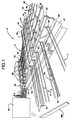
- panel assembly device P for assembling a plurality glass blocks 10 into a panel.
- Glass blocks 10 as illustrated herein, have a generally, three dimensional rectangular configuration.
- Each block 10 includes upper and lower horizontal end walls 12 and 14, respectively, and four vertical side walls 16.
- the side walls and end walls form raised edge portions 18 at their junctions.
- these raised end portions 18 result in the creation of joint cavities 18a being formed between adjacent blocks, the formation of these cavities 18a allow panel assembly device P to internally caulk and seal upper and lower adjacent edge portions 18 of glass blocks 10 when they are positioned on a surface, as described below.
- Panel assembling device P includes spacing rack 20, support frame 22, and moving manifolds 26 (only one bank being shown for convenience, the other being represented by schematic box 26a). It is understood that box 26a is, simply, a duplicate of manifold 26 which controls the adhesive process effected in the joints and cavities at right angles to those associated with manifold 26.
- Support frame 22 is the base of the structure and supports spacing rack 20 and moving manifold 26. While only a partial view of support frame 22 is shown in Figure 1, an entire plan view of support frame 22 is shown in Figure 6. With particular reference to Figure 6, then, support frame 22 is generally L-shaped and includes two vertical end members 23, two outer vertical side members 24, and two vertical inner side members 25. Support frame 22 also includes two interfacing members 27, which are perpendicular to one another. Each interfacing member 27 is disposed between and parallel to an end member 23 and an outer side member 24.
- Spacing rack 20 is positioned and defined by interfacing member 27, and is designed to receive and retain glass blocks 10 while they are assembled into a panel. Spacing rack 20 is positioned in such a manner so that the two perpendicularly disposed manifolds 26, 26a are able to effect the adhesive process between all interfaces of adjacent blocks 10.
- Moving manifolds 26, 26a are carried by support frame 22. Each moving manifold 26, 26a is disposed between and is parallel to a vertical end member 23 and an interfacing member 27. Moving manifolds 26, 26a move between vertical end members 23 and spacing rack 20, to interface with and internally caulk glass blocks 10 positioned on spacing rack 20.
- Each moving manifold 26, 26a includes a plurality of feed tube devices F attached thereon, which function to internally caulk and seal glass blocks 10.
- each moving manifold 26, 26a includes five feed tube devices. It is understood, however, that each manifold may include more or less feed tube devices to meet various needs.
- Sealant is received by manifolds 26, 26a from supply feed 31 via feed lines 31a (lines to manifold 26a not being shown for convenience, and being duplicates of those to manifold 26).
- moving manifolds, 26, 26a feed sealant to feed tube devices F which dispense the sealant into the internal interfaces of adjacent glass blocks at the appropriate time, as described more fully below.
- the glass blocks 10 In order to properly caulk and seal the seams created between internal edge portions 18 of adjacent glass blocks by manifolds 26, 26a the glass blocks 10 must be properly spaced. This is accomplished by way of spacing rack 20.
- spacing rack 20 is generally square in plan and defined by outer side members 24 and interfacing members 27.
- Rack 20 includes two guide bars 28 which are perpendicular to each other and disposed directly above interfacing member 27.
- guide bars 28 each include a plurality of slotted portions 29 (here, five to accommodate the five feed tubes F are associated therewith).
- Each slotted portion 29 interacts with a respective feed tube devices F, to position the respective feed tube device F as it is inserted into cavities 18a by moving manifolds 26, 26a.
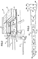
- Spacing rack 20 also includes a plurality of spacing rails 30, which support and space glass blocks 10 as they are assembled. Spacing rails 30 are secured to support frame 22 by a plurality of spaced support rods 34 which are disposed perpendicularly through spacing rails 30. Support rods 34 are equally spaced and secured between vertical side members 24 and interfacing members 27. In certain preferred embodiments of this invention, spacing rails 30 are spaced apart at a distance equal to the length of lower horizontal end wall 14 of glass blocks 10. Spacing rails 30 include machined grooves 40 along their top surface (see Figure 2), which are also placed at distances equal to the width of lower horizontal end member 14 of glass blocks 10.
- Grooves 40 are preferably rectangular in shape to receive lower rectangular stem portion 57 ( Figure 5a) of spacers 44 which operate to space and align opposing corners of glass blocks 10 in a manner which creates upper and lower spacing for the adhesive between adjacent upper and lower edge portions 18 of continuous blocks.
- grooves 40 and spacing members 30 are appropriately located so that spacers 44 provide an appropriately sized and precisely aligned space between contiguous blocks which deters sealant from leaking or penetrating through the intersection during assembly of the panel.
- spacers 44 may also be placed on the top intersections of adjacent glass blocks if desired.
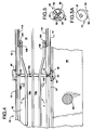
- spacer 44 A more detailed view of spacer 44 is shown with reference to Figures 5 and 5a.
- spacers 44 include a base member 50 and on its upper surface, four concave side surfaces 52 with fins 54 extending from the intersection of side surfaces 52 to the perimeter of base member 56.
- a single stem 57 is provided on the lower surface as shown in Figure 5a.
- Stem 57 is shown as substantially square (e.g. a four point star) in longitudinal cross section.
- spacers 44 when placed in groove 40 may be slid there along and automatically hold blocks 10 in their proper spaced alignment during the sealing process with the adhesive.
- side surfaces 52 of spacers 44 are constructed so as to receive a respective curved corner surface of a glass block 10.
- Side surfaces 52 may, if desired be somewhat concave if desired to accommodate the curvature in the corners of blocks 10. This is not necessary, however, and spacers 54 generally triangular or rectangular cross sectional in shape have been formed adequate for the intended purpose.
- the spacers may be made from a plastic material and should be relatively inexpensive to manufacture. Spacers 44, of course, are merely used to align blocks 10 during manufacture, and do not become integral with the panel. As such, they may be reused during subsequent processing.
- moving manifolds 26, 26a are supported by and travel on a pair of manifold support rods 70, which are disposed along opposite ends of manifolds 26, 26a.
- manifold support rods 70 are secured between a vertical end member 23 of support frame 22 and an interfacing member 27.
- Manifold support rods 70 are placed such that they permit movement of moving manifolds 26, 26a from vertical end member 23 to interfacing member 27.
- Moving manifolds 26, 26a are generally rectangular in shape and each has the appearance of a vertical wall.
- a plurality of feed holes are disposed on manifolds 26 which receive sealant via feed lines 31a from supply feed 31.
- five pairs of threaded shafts are disposed at the exit of the feed holes on the surface of the manifold closest to spacing rack 20. Each pair of vertically disposed threaded shafts engages and secures a feed tube device F.
- moving manifolds 26, 26a receive sealant from supply feed 31 and dispense the sealant (preferably silicone) through a plurality of feed tube devices F.
- Moving manifolds 26, 26a move between vertical end member 23 of support frame 22 and spacing rack 20.
- Each moving manifold 26, 26a is driven by a main drive screw 84.
- Main drive screw 84 operates to push and pull manifolds 26, 26a and is conventionally powered by an air or hydraulic mechanism, or the like.
- the amount of sealant dispensed from supply feed 31 to manifolds 26, 26a is controlled by a metering device 80.
- Each feed tube device F has a metering device 80 associated with it.
- Each feed tube device F includes a pair of elongated feed tubes 82.
- Each tube includes a rigid tube member 86 and a flexible tube member 90 which is of a smaller diameter than the rigid tube member 86.
- the rigid and flexible tube members 86 and 90 may be secured by brazing at their interface 91.
- Rigid tube members 86 are relatively straight and are secured in spaced parallel relationship by two rigid cross members 94, which are attached perpendicular to the longitudinal axis of rigid tube members 86.
- Rigid hollow tube members 86 include orifice entrances 96 at distal ends 100 for receiving a sealant to be applied to the glass blocks 10.
- each flexible tube member 90 is not secured to one another, and are constructed to flare outwardly.
- Each flexible tube member 90 includes a first portion 92, substantially concentric with longitudinal axis of large tube 86 to which it is corrected.
- tube members 90 include a second angled outwardly flared portion 93, and a third parallel portion 94 terminating in distal end 102 whose mechanism is described below. While flared, it is to be seen that in the preferred embodiments of this invention all portions of both flexible tube members 90 lie in substantially the same horizontal plane, although this is not an absolute necessity so long as third portion 110 is properly located so as to distribute the adhesive at the proper location as further described below.
- First portions 92 like rigid tube members 86, are substantially parallel to each other.
- Flexible tube members 90 each include a protruding end portion or tip 104 located at a distal end 102 of third portion 94.
- tip 104 located proximate to tip 104, is an aperture 108 disposed on opposing surfaces 110 of portions 94.
- apertures 108 are located such that they abut or face the upper and lower joint between adjacent blocks which are to receive the adhesive sealant material, and thus are located close to their respective tip 104.
- tips 104 act by their outward bias to compact and compress the sealant into the seams as the sealant is released from apertures 108 (see Figure 4), much in the same way as a caulking tool.
- the sealant is automatically beaded and aesthetically formed between the seams as the compacting tips 104 move along the joint.
- the joints formed between adjacent blocks are preferably slightly smaller than the width of the tip 104. In this way, tip 104 tools sealant into the seam without completely extending through the seam, leaving an aesthetic, but highly uniform, compacted, and strongly adhered joint.
- FIG. 7(a) illustrates the aforesaid tip 104.
- tip 104 is essentially spherical.
- Figure 8(a) illustrates that tip 104 preferably has two flat side portions 105, and a semi-spherical compacting head 106. The side portions 105 ride the inner surfaces of adjacent glass blocks 10 as compacting head 106 tools the sealant into the slot.
- Figure 7(b) illustrates a hook-like tip 107.
- Hook-like tip 107 has a rounded compacting head portion 108 with two flat side portions 109, as illustrated with reference to Figure 8(b).
- Figure 7(c) illustrates another embodiment with a cube-like tip 110.
- Cube-like tip 110 includes two flat side portions 111 and a flat compacting head portion 112, as illustrated with reference to Figure 8(c).
- Figure 7(d) illustrates yet another embodiment with a triangular shaped tip 113.
- Triangular shaped tip 113 includes two flat angled portions 114 and a pointed compacting head portion 115 which compresses the sealant into the joint as shown with reference to Figure 8(d).
- FIG 7(e) illustrates another embodiment with a swivel-like tip 116.
- Swivel-like tip 116 includes two flat side portions 117 which ride the inner surfaces of adjoining blocks and a rounded compacting head portion 118 which compacts the sealant into the slot, as illustrated with reference to Figure 8(e).
- the invention is not limited to the illustrated embodiments which are just given as examples.
- the shape of flexible tube members 90 aid in the proper functioning of feed tube devices F. Because of the spring-like relation, the tips 104 have a natural tendency to want to spring through the intersection of four adjacent blocks, an incident which if allowed to occur could injure the tubes and/or simply stop the process of smooth movement of the tubes in the joint cavities. Third portion 94 prevents tips 104 from continuing its natural springing motion through the intersection. While the upper and lower joints are smaller than the width of tip 104, the intersection of all four blocks is larger. Thus, if feed tubes 82 were straight and did not extend out and then flatten, (i.e. resume a parallel posture) tip 104 would extend through the intersection, causing tip 104 to be wedged in the intersection. Portions 94, being of sufficient length prevent tips 104 from penetrating through the intersections of adjacent blocks 10, because as the feed tube devices F are withdrawn, portions 94 cross the intersection first, preventing tips 104 from springing through the intersections.
- Rigid tube members 86 include threaded nuts 120 at their distal ends 100 for securement to the moving manifolds 26, 26a. With reference back to Figure 1, threaded nuts 120 are screwed into complimentary threaded shafts (not shown) on moving manifolds 26 and 26a. In certain preferred embodiments, moving manifolds 26 and 26a include five pairs of threaded shafts which are vertically disposed so as to receive complimentary threaded nuts 120 of feed tubes devices F.
- feed tube devices F are affixed and disposed on moving manifolds 26, 26a which move as aforesaid thereby to cause feed tubes 82 to enter the appropriate joint cavity defined between adjacent blocks in the stack.
- feed tube devices F must slide through respective vertical slotted portion 29 of guide bar 28. By establishing the appropriate height in slot 29, the distal ends 102 of tubes F are compressed to less than their normal spacing, thus allowing them to initially enter the joint cavity of the blocks.
- tubes F move farther through and past slots 29 such that the flared portions 93 of tubes F engage slots 29, the compressed distal ends 102 separate until they rest, still outwardly biased in the block joint to be sealed. Retraction of tubes F creates the opposite effect, readying distal ends 102 for the next insertion when a new panel stack is presented to it for sealing.
- tips 104 compact the sealant into upper and lower joints between the blocks 10. The sealant is thus tooled to reach internally, while applying sealant to both top and the bottom interfaces at the same time. It is understood that the lengths of feed tube devices F may be such that they completely traverse spacing rack 20.
- glass blocks 10 In order to assemble a panel according to the present invention, glass blocks 10 must be properly positioned on panel assembly device P. This is accomplished by positioning spacers 44 into machined grooves 40 of spacing rack 20. Glass blocks 10 are then positioned on top of spacers 44. The glass blocks 10 and spacers 44 may be put onto spacing rack 20 by an unskilled worker, and should take just a few minutes. Spacers 44 may also be placed on the top interfaces of adjacent blocks, but in may operations this has been not found essential to accomplish. After glass blocks 10 are properly positioned, the operation of panel assembly device panel P will begin.
- support frame 22 carries perpendicularly disposed moving manifolds 26, 26a.
- tubes F are in the position shown in Figure 2.
- the tubes due to the outward spring bias tend to follow the extremity of slots 29 such that as the tube ends 102 enter the cavity, flared portions 93 begin to contact the extremities of slots 29, commencing the separation of opposing distal ends 102.
- Continued movement of the manifolds causes the distal ends to separate until they contact and ride along the joint to be sealed (as shown in Figure 4).
- the sealant used is flexible and adheres naturally to the glass. This decreases the chance of the panel shattering as opposed to the use of mortar.
- the sealant used in these preferred embodiments is preferably silicone a example of which is ( GIVE COMMERCIAL NAME -by trademark manufacturer). The entire operation described above takes just a few minutes to perform, yet results in a more structurally sound panel than those constructed from prior art devices and methods.
- the panel may be conveyed off of spacing rack 20, while panel assembly device P is set up for another assembling process.
- spacers 44 may slightly adhere to the panel, but may be easily popped off and subsequently re-used.
- the process and apparatus described offers great improvements over the prior art in that a stronger glass block may be constructed at a traction of the cost.
- the time required to produce such panels is greatly reduced as well as quality control problems associated with constructing the panel on-site.
Landscapes
- Engineering & Computer Science (AREA)
- Architecture (AREA)
- Civil Engineering (AREA)
- Structural Engineering (AREA)
- Joining Of Glass To Other Materials (AREA)
Applications Claiming Priority (2)
| Application Number | Priority Date | Filing Date | Title |
|---|---|---|---|
| US08/873,127 US5890335A (en) | 1997-06-11 | 1997-06-11 | Glass block panel construction and method and apparatus for fabrication thereof |
| US873127 | 1997-06-11 |
Publications (2)
| Publication Number | Publication Date |
|---|---|
| EP0884430A2 true EP0884430A2 (de) | 1998-12-16 |
| EP0884430A3 EP0884430A3 (de) | 1999-08-25 |
Family
ID=25361025
Family Applications (1)
| Application Number | Title | Priority Date | Filing Date |
|---|---|---|---|
| EP98110257A Withdrawn EP0884430A3 (de) | 1997-06-11 | 1998-06-05 | Konstruktion einer Glasbaustein-Wand und Verfahren und Vorrichtung zu ihrer Herstellung |
Country Status (3)
| Country | Link |
|---|---|
| US (2) | US5890335A (de) |
| EP (1) | EP0884430A3 (de) |
| CA (1) | CA2239061C (de) |
Families Citing this family (12)
| Publication number | Priority date | Publication date | Assignee | Title |
|---|---|---|---|---|
| US6251324B1 (en) * | 1999-09-22 | 2001-06-26 | Trend Products, Inc. | Applicator for applying sealant onto a glass block and method of use |
| US6553733B1 (en) | 1999-11-10 | 2003-04-29 | Pittsburgh Corning Corporation | Glass block with internal capsule |
| US6652794B2 (en) | 2000-12-19 | 2003-11-25 | Pcc Structurals, Inc. | Casting pattern seam tool and method for its use |
| US20060010810A1 (en) * | 2002-12-18 | 2006-01-19 | Arkadiusz Muszynski | Wall construction using hollow glass building elements |
| US7373763B2 (en) * | 2003-03-13 | 2008-05-20 | Extech/Exterior Technologies, Inc. | Glass block assembly |
| USD494042S1 (en) * | 2003-04-30 | 2004-08-10 | Seattle Glass Block | Glass block spacer |
| ITVE20030023A1 (it) * | 2003-06-10 | 2004-12-11 | Aghebo Sistemi S R L | Complesso di elementi strutturali per realizzare pareti in vetroresina. |
| US20090320921A1 (en) * | 2008-02-01 | 2009-12-31 | Grommesh Robert C | Photovoltaic Glazing Assembly and Method |
| US20090194147A1 (en) * | 2008-02-01 | 2009-08-06 | Cardinal Ig Company | Dual seal photovoltaic assembly and method |
| CA2720257A1 (en) * | 2008-04-10 | 2009-10-15 | Cardinal Ig Company | Glazing assemblies that incorporate photovoltaic elements and related methods of manufacture |
| WO2009126186A1 (en) * | 2008-04-10 | 2009-10-15 | Cardinal Ig Company | Manufacturing of photovoltaic subassemblies |
| CN111173179A (zh) * | 2020-01-14 | 2020-05-19 | 湖南美美幕墙装饰有限公司 | 一种幕墙立柱与横梁的连接结构及方式 |
Family Cites Families (28)
| Publication number | Priority date | Publication date | Assignee | Title |
|---|---|---|---|---|
| US2167764A (en) * | 1936-09-12 | 1939-08-01 | Pittsburgh Plate Glass Co | Glass building block |
| US2162987A (en) * | 1937-09-10 | 1939-06-20 | Corning Glass Works | Glass construction block and wall assembly |
| US2232798A (en) * | 1938-07-14 | 1941-02-25 | Libbey Owens Ford Glass Co | Wall construction |
| US2895325A (en) * | 1953-03-02 | 1959-07-21 | Intonacatrice Tigre S R L | Spraying apparatus |
| US2835623A (en) * | 1955-08-24 | 1958-05-20 | Owens Illinois Glass Co | Method of forming a unitary panel of glass blocks |
| US2972783A (en) * | 1957-12-02 | 1961-02-28 | Kimble Glass Co | Method for fabricating glass block panels |
| US3234699A (en) * | 1961-04-25 | 1966-02-15 | Nat Lead Co | Building block assembly construction and method of erection |
| DE1914144A1 (de) * | 1968-03-26 | 1970-11-05 | Villeroy & Boch | Tafel zum Verkleiden von Wandflaechen sowie Verfahren und Vorrichtung zu ihrer Herstellung |
| US3599299A (en) * | 1968-12-12 | 1971-08-17 | Raymond Int Inc | Lining machine |
| DE2252408C3 (de) * | 1972-10-25 | 1975-06-12 | Saint-Gobain Industries, Neuilly- Sur-Seine (Frankreich) | Verfahren und Vorrichtungen zur Herstellung eines vorgefertigten Wandteiles aus Glasbausteinen |
| US4058943A (en) * | 1976-06-03 | 1977-11-22 | Sturgill Lawrence W | Glass block panel |
| DE3234320C1 (de) * | 1982-09-16 | 1983-10-20 | Flachglas AG, 8510 Fürth | Anlage fuer die Randversiegelung von Isolierglaseinheiten |
| DE3310441C1 (de) * | 1983-03-23 | 1984-09-06 | Flachglas AG, 8510 Fürth | Anlage fuer die Randversiegelung von Isolierglaseinheiten |
| DE3424173C1 (de) * | 1984-06-30 | 1985-11-07 | Johann 8900 Augsburg Thaler | Vorgefertigtes Bauelement aus Glashohlbausteinen |
| US4774793A (en) * | 1986-03-24 | 1988-10-04 | Emil Mayer | Glass block panel construction and device for use in same |
| EP0337978A1 (de) * | 1988-04-11 | 1989-10-18 | Peter Lisec | Verfahren zum Füllen der Randfugen von Isolierglasscheiben mit Versiegelungsmasse |
| US5017113A (en) * | 1988-05-02 | 1991-05-21 | Heaton Donald E | Filleting attachment for a caulking gun |
| US5042210A (en) * | 1988-08-25 | 1991-08-27 | Innovative Building Products, Inc. | Glass-block panels and method of fabrication thereof |
| US4971537A (en) * | 1989-06-29 | 1990-11-20 | Harry O. Hoffman | Apparatus for puttying elongated plywood boards |
| US5009048A (en) * | 1989-08-15 | 1991-04-23 | Acrymet Industries Inc. | Glass block walls using acrylic or glass filters |
| US4986048A (en) * | 1990-01-11 | 1991-01-22 | Pittsburgh Corning Corporation | Method and apparatus for erecting a glass block wall |
| US5033245A (en) * | 1990-01-16 | 1991-07-23 | Glass Alternatives Corp. | Architectural building block |
| US5430985A (en) * | 1990-09-14 | 1995-07-11 | Coleman; William J. | Building block wall connector strip and method of assembling a block wall utilizing such strip |
| US5232608A (en) * | 1991-02-08 | 1993-08-03 | Emil Mayer | Template for forming glass block panel modules |
| US5259161A (en) * | 1991-06-03 | 1993-11-09 | Carter Frank P | Vertical and horizontal reinforcement and spacing guide for panels constructed of blocks |
| US5367846A (en) * | 1993-06-14 | 1994-11-29 | Vonroenn, Jr.; Kenneth F. | Interlocking glass block system |
| US5448864A (en) * | 1993-06-22 | 1995-09-12 | Rosamond; John E. | Multi-light glass block panel assembly and method |
| US5485702A (en) * | 1994-03-25 | 1996-01-23 | Glenn Sholton | Mortarless glass block assembly |
-
1997
- 1997-06-11 US US08/873,127 patent/US5890335A/en not_active Expired - Lifetime
-
1998
- 1998-05-15 US US09/079,275 patent/US6033200A/en not_active Expired - Lifetime
- 1998-05-28 CA CA002239061A patent/CA2239061C/en not_active Expired - Fee Related
- 1998-06-05 EP EP98110257A patent/EP0884430A3/de not_active Withdrawn
Also Published As
| Publication number | Publication date |
|---|---|
| CA2239061C (en) | 2004-02-03 |
| CA2239061A1 (en) | 1998-12-11 |
| US5890335A (en) | 1999-04-06 |
| EP0884430A3 (de) | 1999-08-25 |
| US6033200A (en) | 2000-03-07 |
Similar Documents
| Publication | Publication Date | Title |
|---|---|---|
| CA2239061C (en) | Glass block panel construction and method and apparatus for fabrication thereof | |
| CA2033839C (en) | Method and apparatus for erecting a glass block wall | |
| US5491939A (en) | Prefabricated staircase unit | |
| EP2422033A1 (de) | Verfahren zum zusammenbauen von isolierglasscheiben, die drei zueinander parallele glasplatten haben | |
| US4953337A (en) | Method and apparatus for constructing a masonry structure | |
| US20020066257A1 (en) | Synthetic core construction panel and apparatus for making same | |
| KR20200072435A (ko) | 타일 패널과 그의 제조방법 및 이를 이용한 시공방법 | |
| US5402610A (en) | Standardized step module for building prefabricated staircases, process for producing such module, prefabricated staircase and process for assemblying prefabricated staircases | |
| MXPA98004627A (en) | Method and apparatus for the manufacture of panels of glass blocks and panel formed from the mis | |
| JP2832843B2 (ja) | 建築物の外装施工方法 | |
| JPH0355383A (ja) | サッシの建込み治具と建込み操作装置 | |
| DE19812255C2 (de) | Verfahren zum Erstellen einer Wand | |
| DE1955361A1 (de) | Verfahren und Vorrichtung zur horizontalen Vorfertigung eines Steinverbandes | |
| JPS61126222A (ja) | 型枠用板 | |
| JPH04250243A (ja) | 外壁の施工方法 | |
| JPH0336364A (ja) | タイル貼り付け方法及びその装置 | |
| AU663959B2 (en) | Prefabricated building construction | |
| JPH10245993A (ja) | 目地用モルタル施工用具 | |
| DE8620150U1 (de) | Bodenplatte für aufgeständerte Doppelböden | |
| JP2779050B2 (ja) | 基礎構造の形成方法 | |
| JPH02128065A (ja) | 自動モルタル均し装置 | |
| JPH02128066A (ja) | 自動タイル施工装置 | |
| JPH0543148Y2 (de) | ||
| EP0977927A1 (de) | Verfahren und vorrichtung zur durchführung des verfahrens zum erstellen eines mauerwerks und dazu verwendbares vorgefertigtes bauelement | |
| JPS649426B2 (de) |
Legal Events
| Date | Code | Title | Description |
|---|---|---|---|
| PUAI | Public reference made under article 153(3) epc to a published international application that has entered the european phase |
Free format text: ORIGINAL CODE: 0009012 |
|
| AK | Designated contracting states |
Kind code of ref document: A2 Designated state(s): BE CH DE DK ES FR GB IT LI NL SE |
|
| AX | Request for extension of the european patent |
Free format text: AL;LT;LV;MK;RO;SI |
|
| PUAL | Search report despatched |
Free format text: ORIGINAL CODE: 0009013 |
|
| AK | Designated contracting states |
Kind code of ref document: A3 Designated state(s): AT BE CH CY DE DK ES FI FR GB GR IE IT LI LU MC NL PT SE |
|
| AX | Request for extension of the european patent |
Free format text: AL;LT;LV;MK;RO;SI |
|
| 17P | Request for examination filed |
Effective date: 19991119 |
|
| AKX | Designation fees paid |
Free format text: BE CH DE DK ES FR GB IT LI NL SE |
|
| 17Q | First examination report despatched |
Effective date: 20030124 |
|
| GRAP | Despatch of communication of intention to grant a patent |
Free format text: ORIGINAL CODE: EPIDOSNIGR1 |
|
| STAA | Information on the status of an ep patent application or granted ep patent |
Free format text: STATUS: THE APPLICATION IS DEEMED TO BE WITHDRAWN |
|
| 18D | Application deemed to be withdrawn |
Effective date: 20050621 |