EP0884646A2 - Imprimante, système d'impression ainsi qu'une méthode d'impression utilisant du papier comprenant des microcapsules photosensibles - Google Patents
Imprimante, système d'impression ainsi qu'une méthode d'impression utilisant du papier comprenant des microcapsules photosensibles Download PDFInfo
- Publication number
- EP0884646A2 EP0884646A2 EP98304615A EP98304615A EP0884646A2 EP 0884646 A2 EP0884646 A2 EP 0884646A2 EP 98304615 A EP98304615 A EP 98304615A EP 98304615 A EP98304615 A EP 98304615A EP 0884646 A2 EP0884646 A2 EP 0884646A2
- Authority
- EP
- European Patent Office
- Prior art keywords
- print paper
- carriage
- printer
- microcapsules
- roller
- Prior art date
- Legal status (The legal status is an assumption and is not a legal conclusion. Google has not performed a legal analysis and makes no representation as to the accuracy of the status listed.)
- Withdrawn
Links
- 239000003094 microcapsule Substances 0.000 title claims abstract description 133
- 238000007639 printing Methods 0.000 title claims abstract description 45
- 238000000034 method Methods 0.000 title claims abstract description 16
- 239000000463 material Substances 0.000 claims abstract description 84
- 210000000078 claw Anatomy 0.000 claims description 23
- 238000000016 photochemical curing Methods 0.000 claims description 22
- 238000010438 heat treatment Methods 0.000 claims description 13
- 238000005452 bending Methods 0.000 claims description 6
- 238000005299 abrasion Methods 0.000 claims description 5
- 239000011248 coating agent Substances 0.000 claims description 5
- 238000000576 coating method Methods 0.000 claims description 5
- 239000004033 plastic Substances 0.000 claims description 5
- 238000003825 pressing Methods 0.000 claims description 5
- 238000005096 rolling process Methods 0.000 abstract description 45
- 230000005540 biological transmission Effects 0.000 description 17
- 238000011144 upstream manufacturing Methods 0.000 description 6
- 238000006243 chemical reaction Methods 0.000 description 5
- 239000002184 metal Substances 0.000 description 5
- 229910052751 metal Inorganic materials 0.000 description 5
- 239000000203 mixture Substances 0.000 description 5
- 230000006870 function Effects 0.000 description 4
- 238000004519 manufacturing process Methods 0.000 description 4
- 230000035945 sensitivity Effects 0.000 description 4
- YCKRFDGAMUMZLT-UHFFFAOYSA-N Fluorine atom Chemical compound [F] YCKRFDGAMUMZLT-UHFFFAOYSA-N 0.000 description 3
- 239000004809 Teflon Substances 0.000 description 3
- 229920006362 Teflon® Polymers 0.000 description 3
- 239000013078 crystal Substances 0.000 description 3
- 230000007423 decrease Effects 0.000 description 3
- 229910052731 fluorine Inorganic materials 0.000 description 3
- 239000011737 fluorine Substances 0.000 description 3
- 239000011347 resin Substances 0.000 description 3
- 229920005989 resin Polymers 0.000 description 3
- 239000003795 chemical substances by application Substances 0.000 description 2
- 239000003086 colorant Substances 0.000 description 2
- 230000000295 complement effect Effects 0.000 description 2
- 238000001723 curing Methods 0.000 description 2
- 238000006073 displacement reaction Methods 0.000 description 2
- 229910001220 stainless steel Inorganic materials 0.000 description 2
- 239000010935 stainless steel Substances 0.000 description 2
- 238000004804 winding Methods 0.000 description 2
- 108010010803 Gelatin Proteins 0.000 description 1
- 241000238370 Sepia Species 0.000 description 1
- 229910000831 Steel Inorganic materials 0.000 description 1
- 239000011358 absorbing material Substances 0.000 description 1
- 238000013459 approach Methods 0.000 description 1
- 239000002775 capsule Substances 0.000 description 1
- 230000008878 coupling Effects 0.000 description 1
- 238000010168 coupling process Methods 0.000 description 1
- 238000005859 coupling reaction Methods 0.000 description 1
- 230000003247 decreasing effect Effects 0.000 description 1
- 238000001514 detection method Methods 0.000 description 1
- 229920000159 gelatin Polymers 0.000 description 1
- 239000008273 gelatin Substances 0.000 description 1
- 235000019322 gelatine Nutrition 0.000 description 1
- 235000011852 gelatine desserts Nutrition 0.000 description 1
- 238000003780 insertion Methods 0.000 description 1
- 230000037431 insertion Effects 0.000 description 1
- 239000004973 liquid crystal related substance Substances 0.000 description 1
- 238000000465 moulding Methods 0.000 description 1
- 239000003973 paint Substances 0.000 description 1
- 230000010363 phase shift Effects 0.000 description 1
- 229920006267 polyester film Polymers 0.000 description 1
- 238000002360 preparation method Methods 0.000 description 1
- 230000001902 propagating effect Effects 0.000 description 1
- 230000000717 retained effect Effects 0.000 description 1
- 230000002441 reversible effect Effects 0.000 description 1
- 230000035939 shock Effects 0.000 description 1
- 239000010959 steel Substances 0.000 description 1
- 230000001360 synchronised effect Effects 0.000 description 1
- 229910052714 tellurium Inorganic materials 0.000 description 1
- PORWMNRCUJJQNO-UHFFFAOYSA-N tellurium atom Chemical compound [Te] PORWMNRCUJJQNO-UHFFFAOYSA-N 0.000 description 1
Images


Classifications
-
- B—PERFORMING OPERATIONS; TRANSPORTING
- B41—PRINTING; LINING MACHINES; TYPEWRITERS; STAMPS
- B41J—TYPEWRITERS; SELECTIVE PRINTING MECHANISMS, i.e. MECHANISMS PRINTING OTHERWISE THAN FROM A FORME; CORRECTION OF TYPOGRAPHICAL ERRORS
- B41J11/00—Devices or arrangements of selective printing mechanisms, e.g. ink-jet printers or thermal printers, for supporting or handling copy material in sheet or web form
- B41J11/02—Platens
- B41J11/04—Roller platens
-
- B—PERFORMING OPERATIONS; TRANSPORTING
- B41—PRINTING; LINING MACHINES; TYPEWRITERS; STAMPS
- B41J—TYPEWRITERS; SELECTIVE PRINTING MECHANISMS, i.e. MECHANISMS PRINTING OTHERWISE THAN FROM A FORME; CORRECTION OF TYPOGRAPHICAL ERRORS
- B41J19/00—Character- or line-spacing mechanisms
- B41J19/18—Character-spacing or back-spacing mechanisms; Carriage return or release devices therefor
- B41J19/20—Positive-feed character-spacing mechanisms
-
- B—PERFORMING OPERATIONS; TRANSPORTING
- B41—PRINTING; LINING MACHINES; TYPEWRITERS; STAMPS
- B41J—TYPEWRITERS; SELECTIVE PRINTING MECHANISMS, i.e. MECHANISMS PRINTING OTHERWISE THAN FROM A FORME; CORRECTION OF TYPOGRAPHICAL ERRORS
- B41J11/00—Devices or arrangements of selective printing mechanisms, e.g. ink-jet printers or thermal printers, for supporting or handling copy material in sheet or web form
- B41J11/0045—Guides for printing material
- B41J11/005—Guides in the printing zone, e.g. guides for preventing contact of conveyed sheets with printhead
-
- B—PERFORMING OPERATIONS; TRANSPORTING
- B41—PRINTING; LINING MACHINES; TYPEWRITERS; STAMPS
- B41J—TYPEWRITERS; SELECTIVE PRINTING MECHANISMS, i.e. MECHANISMS PRINTING OTHERWISE THAN FROM A FORME; CORRECTION OF TYPOGRAPHICAL ERRORS
- B41J11/00—Devices or arrangements of selective printing mechanisms, e.g. ink-jet printers or thermal printers, for supporting or handling copy material in sheet or web form
- B41J11/36—Blanking or long feeds; Feeding to a particular line, e.g. by rotation of platen or feed roller
- B41J11/42—Controlling printing material conveyance for accurate alignment of the printing material with the printhead; Print registering
-
- B—PERFORMING OPERATIONS; TRANSPORTING
- B41—PRINTING; LINING MACHINES; TYPEWRITERS; STAMPS
- B41J—TYPEWRITERS; SELECTIVE PRINTING MECHANISMS, i.e. MECHANISMS PRINTING OTHERWISE THAN FROM A FORME; CORRECTION OF TYPOGRAPHICAL ERRORS
- B41J13/00—Devices or arrangements of selective printing mechanisms, e.g. ink-jet printers or thermal printers, specially adapted for supporting or handling copy material in short lengths, e.g. sheets
- B41J13/02—Rollers
- B41J13/025—Special roller holding or lifting means, e.g. for temporarily raising one roller of a pair of nipping rollers for inserting printing material
-
- B—PERFORMING OPERATIONS; TRANSPORTING
- B41—PRINTING; LINING MACHINES; TYPEWRITERS; STAMPS
- B41J—TYPEWRITERS; SELECTIVE PRINTING MECHANISMS, i.e. MECHANISMS PRINTING OTHERWISE THAN FROM A FORME; CORRECTION OF TYPOGRAPHICAL ERRORS
- B41J2/00—Typewriters or selective printing mechanisms characterised by the printing or marking process for which they are designed
- B41J2/005—Typewriters or selective printing mechanisms characterised by the printing or marking process for which they are designed characterised by bringing liquid or particles selectively into contact with a printing material
- B41J2/01—Ink jet
-
- B—PERFORMING OPERATIONS; TRANSPORTING
- B41—PRINTING; LINING MACHINES; TYPEWRITERS; STAMPS
- B41J—TYPEWRITERS; SELECTIVE PRINTING MECHANISMS, i.e. MECHANISMS PRINTING OTHERWISE THAN FROM A FORME; CORRECTION OF TYPOGRAPHICAL ERRORS
- B41J2/00—Typewriters or selective printing mechanisms characterised by the printing or marking process for which they are designed
- B41J2/435—Typewriters or selective printing mechanisms characterised by the printing or marking process for which they are designed characterised by selective application of radiation to a printing material or impression-transfer material
- B41J2/44—Typewriters or selective printing mechanisms characterised by the printing or marking process for which they are designed characterised by selective application of radiation to a printing material or impression-transfer material using single radiation source per colour, e.g. lighting beams or shutter arrangements
-
- B—PERFORMING OPERATIONS; TRANSPORTING
- B41—PRINTING; LINING MACHINES; TYPEWRITERS; STAMPS
- B41J—TYPEWRITERS; SELECTIVE PRINTING MECHANISMS, i.e. MECHANISMS PRINTING OTHERWISE THAN FROM A FORME; CORRECTION OF TYPOGRAPHICAL ERRORS
- B41J2/00—Typewriters or selective printing mechanisms characterised by the printing or marking process for which they are designed
- B41J2/435—Typewriters or selective printing mechanisms characterised by the printing or marking process for which they are designed characterised by selective application of radiation to a printing material or impression-transfer material
- B41J2/447—Typewriters or selective printing mechanisms characterised by the printing or marking process for which they are designed characterised by selective application of radiation to a printing material or impression-transfer material using arrays of radiation sources
- B41J2/455—Typewriters or selective printing mechanisms characterised by the printing or marking process for which they are designed characterised by selective application of radiation to a printing material or impression-transfer material using arrays of radiation sources using laser arrays, the laser array being smaller than the medium to be recorded
-
- B—PERFORMING OPERATIONS; TRANSPORTING
- B41—PRINTING; LINING MACHINES; TYPEWRITERS; STAMPS
- B41J—TYPEWRITERS; SELECTIVE PRINTING MECHANISMS, i.e. MECHANISMS PRINTING OTHERWISE THAN FROM A FORME; CORRECTION OF TYPOGRAPHICAL ERRORS
- B41J2/00—Typewriters or selective printing mechanisms characterised by the printing or marking process for which they are designed
- B41J2/435—Typewriters or selective printing mechanisms characterised by the printing or marking process for which they are designed characterised by selective application of radiation to a printing material or impression-transfer material
- B41J2/47—Typewriters or selective printing mechanisms characterised by the printing or marking process for which they are designed characterised by selective application of radiation to a printing material or impression-transfer material using the combination of scanning and modulation of light
- B41J2/471—Typewriters or selective printing mechanisms characterised by the printing or marking process for which they are designed characterised by selective application of radiation to a printing material or impression-transfer material using the combination of scanning and modulation of light using dot sequential main scanning by means of a light deflector, e.g. a rotating polygonal mirror
- B41J2/473—Typewriters or selective printing mechanisms characterised by the printing or marking process for which they are designed characterised by selective application of radiation to a printing material or impression-transfer material using the combination of scanning and modulation of light using dot sequential main scanning by means of a light deflector, e.g. a rotating polygonal mirror using multiple light beams, wavelengths or colours
-
- G—PHYSICS
- G03—PHOTOGRAPHY; CINEMATOGRAPHY; ANALOGOUS TECHNIQUES USING WAVES OTHER THAN OPTICAL WAVES; ELECTROGRAPHY; HOLOGRAPHY
- G03F—PHOTOMECHANICAL PRODUCTION OF TEXTURED OR PATTERNED SURFACES, e.g. FOR PRINTING, FOR PROCESSING OF SEMICONDUCTOR DEVICES; MATERIALS THEREFOR; ORIGINALS THEREFOR; APPARATUS SPECIALLY ADAPTED THEREFOR
- G03F7/00—Photomechanical, e.g. photolithographic, production of textured or patterned surfaces, e.g. printing surfaces; Materials therefor, e.g. comprising photoresists; Apparatus specially adapted therefor
- G03F7/002—Photomechanical, e.g. photolithographic, production of textured or patterned surfaces, e.g. printing surfaces; Materials therefor, e.g. comprising photoresists; Apparatus specially adapted therefor using materials containing microcapsules; Preparing or processing such materials, e.g. by pressure; Devices or apparatus specially designed therefor
- G03F7/0022—Devices or apparatus
Definitions
- the present invention relates to a printer in which a latent image is formed by scanning through a carriage provided with three kinds of light emitting elements consisting red, green, and blue light over print paper onto which photosensitive microcapsules are applied, and by applying a mechanical pressure through a print roller to the print paper with the latent image formed thereon.
- the present invention also relates to a printing system and a printing method using the printer.
- Conventional photosensitive microcapsule type print paper is separated into a roll film with microcapsules encaplulating in combination color developing material and photo-curing material applied thereto and a sheet paper with an image receiving layer applied thereto for carrying out developing by bring the image receiving layer into close contact to the surface of the roll film onto which the microcapsules are applied.
- the roll film is sent, while a carriage provided with LEDs for applying light scans to apply light from the LEDs so as to correspond to image data to selectively cure the photo-curing material.
- the surface of the roll film to which the microcapsules are applied and the image receiving layer of the sheet paper are put together and guided between pressure rollers to apply pressure and collapse microcapsules which were not cured.
- heating is carried out to accelerate developing of color of the color developing material brought into contact with the image receiving layer to develop an image on the sheet paper.
- the roll film is separated from the sheet paper and is wound.
- the conventional printer is comprised of: a roll film support device to which the roll film with the microcapsules applied thereto is attached; a winding device for winding the roll film; a feed roller to send the roll film; a pickup roller for feeding the sheet paper from the cassette; an exposing means for flickeringly applying the light of specific wavelength to the print paper fed from the cassette corresponding to image data externally input such that microcapsules exposed to the light are made to be uncollapsible; a pressurizing means for applying pressure to the roll film and the sheet paper put together and guided between a pair of pressure rollers to collapse the microcapsules which were not exposed to the light and thus did not cure to be in contact with the image receiving layer thereby causing color developing reaction of the color developing material; a heating means for heating the color developing material which can react with the image receiving layer in contact to develop color thereby accelerating
- paper on which a bar code is printed is put on top of the print paper at the top and is fed, the bar code is read and decoded to specify the kind of the print paper, and the intensity or the time period of application of the light of specific wavelength is varied according to the kind of the print paper.
- the conventional printer has the following drawbacks.
- the present invention is made to solve the problems mentioned above of the conventional printer, and therefore has an object of the present invention to provide a printer using print paper with photosensitive microcapsules applied thereto which develops an image by forming a latent image by applying light over print paper with photosensitive microcapsules applied thereto so as to correspond to image data externally input and applying high pressure thus collapsing microcapsules which were not cured and making color developing material brought into contact with image receiving layer.
- Another object of the present invention is to provide the printer which is ultraminiaturized to be palm top.
- Still another object of the present invention is to provide the printer with which, even if the cassette is freely exchanged for another cassette with some of the print paper remaining therein, the kind of the print paper can be specified and thus printing can be carried out while the print paper freely exchanged.
- Yet another object of the present invention is to provide the printer with which the developing time can be shortened.
- a further another object of the present invention is to provide the printer with which displacement of the print paper due to application of pressure can be suppressed to prevent blur of an image and noise caused during printing can be suppressed.
- a still further another object of the present invention is to provide the printer which can smoothly send the print paper.
- a yet further object of the present invention is to provide a printer which, by eliminating deflection of the carriage guided by the carriage guide, can precisely detect the position of the carriage with a linear sensor and can prevent displacement of the position of emission of light, thus preventing a striped pattern and blur of the printed image.
- a still further object of the present invention is to provide a printer of lower manufacturing cost by making smaller the number of parts and by facilitating the assembly.
- a yet further object of the present invention is to provide a printing system and a printing method using these printers.
- a printer using print paper with photosensitive microcapsules applied thereto uses print paper with photosensitive microcapsules encaplulating color developing material and photo-curing material and an image receiving layer applied thereto for developing color by reacting the color developing material with the image receiving layer, and is comprised of a carriage provided with a light emitting element emitting light of specific wavelength for scanning over the print paper with the light emitting element emitting light to form a latent image on the print paper, a carriage guide for guiding movement of the carriage in the scanning direction and a pressurizing means for applying mechanical pressure to the print paper with a latent image formed thereon to collapse microcapsules which were not exposed to the light of specific wavelength and thus did not cure thereby developing the image by reacting the color developing material in the collapsed microcapsules with the image receiving layer.
- a printer using print paper with photosensitive microcapsules applied thereto is comprised of, as the above pressurizing means, a pressure roller which is provided on the carriage and rolls on the print paper guided on a platen by movement of the carriage in the scanning direction, for applying mechanical pressure to collapse microcapsules which were not exposed to the light of specific wavelength and thus did not cure thereby developing the image by reacting the color developing material in the collapsed microcapsules with the image receiving layer.
- a printer using print paper with photosensitive microcapsules applied thereto is comprised of a cassette detachably provided on a printer body for containing a stack of the print paper, the cassette being provided with a code indicating photosensitive characteristics of the contained print paper, a photosensitive characteristics identifying means provided on the carriage for reading the code provided on the cassette thereby identifying the photosensitive characteristics of the print paper and a light emission controlling means for controlling the intensity or the time period of emission of the light of specific wavelength based on the photosensitive characteristics of the print paper identified by the photosensitive characteristics identifying means.
- the above structure using the above pressure roller and the structure having the above cassette for containing the print paper may be combined with each other to structure a printer using print paper with photosensitive microcapsules applied thereto.
- the printer using print paper with photosensitive microcapsules applied thereto is further comprised of a heating means for heating the print paper in the developing process, thereby accelerating the developing speed.
- the printer using print paper with photosensitive microcapsules applied thereto advantageously is further comprised of a pair of paper guides provided on both end portions of the platen which are, when the print paper is not on the platen, pressed by a spring to bring into close contact to each other, such that the space between them is narrower than the width of the print paper, and, when the print paper is introduced on the platen, the space between which is widened such that both ends of the print paper are held.
- the printer using print paper with photosensitive microcapsules applied thereto is advantageously structured such that the space between the pressure roller and the platen is about a half of the thickness of the print paper.
- the printer using print paper with photosensitive microcapsules applied thereto can be structured such that the platen is provided being pressed by a spring in the direction of the pressure roller, the pressure roller is formed of a first roller provided at a position facing the platen and a second roller provided so as to be brought into contact with the first roller, the second roller rolls brought into contact with the carriage guide, and the first roller rolls between the second roller and the print paper guided onto the platen.
- the printer using print paper with photosensitive microcapsules applied thereto is advantageously structured such that, when the print paper is not on the platen, the space between the first roller and the platen is about a half of the thickness of the print paper.
- the printer using print paper with photosensitive microcapsules applied thereto is further comprised of a driving side timing pulley axially supported, a driven side timing pulley axially supported, a timing belt put around the driving side timing pulley and the driven side timing pulley and provided with a pin to engage with the carriage, and a carriage driving means for driving the driving side timing pulley to rotate, wherein the carriage is engaged with the pin so as to reciprocate in the scanning direction according to rotation of the driving side timing pulley.
- the printer using print paper with photosensitive microcapsules applied thereto is further comprised of a driving side timing pulley axially supported, a driven side timing pulley axially supported, a timing belt put around the driving side timing pulley and the driven side timing pulley and provided with a pin to engage with the carriage, a first bevel gear provided coaxially with the driving side timing pulley, and a second bevel gear engaged with the first bevel gear, a back surface thereof being supported by a bracket for preventing bevel gear movement, for receiving thrust by the engagement, wherein the carriage is engaged with the pin so as to reciprocate in the scanning direction according to rotation of the driving side timing pulley.
- one end portion of the carriage guide fits in and fixed to a rectangular hole in a chassis and the other end portion of the carriage guide is passed through an opening formed in the chassis and is screwed to the chassis.
- a printer using print paper with photosensitive microcapsules applied thereto uses print paper with photosensitive microcapsules encaplulating color developing material and photo-curing material and an image receiving layer applied thereto for developing color by reacting the color developing material with the image receiving layer, and is comprised of a cassette detachably provided on a printer body for containing a stack of the print paper, a pickup roller for feeding said print paper from said cassette, a feed roller for sending the print paper fed by the pickup roller, a motor, a power transmitting means for transmitting rotation of the motor to movable elements including the pickup roller and the feed roller, a carriage provided with a light emitting element emitting light of specific wavelength for scanning over the print paper with the light emitting element emitting light to form a latent image on the print paper, a carriage guide for guiding movement of the carriage in the scanning direction, and a pressurizing means for applying mechanical pressure to the print paper with a latent image formed thereon to collapse microcapsules
- the printer using print paper with photosensitive microcapsules applied thereto may further comprises a pinch roller made of plastic material below the feed roller for pinching and sending the print paper.
- the printer using print paper with photosensitive microcapsules applied thereto may be structured such that one side surface of the carriage guide is slidably in contact with one side surface of the carriage, a plate spring is provided on the carriage so as to face the other side surface of the carriage guide, the plate spring being slidably in contact with the other side surface of the carriage guide, and abrasion resistant coating with a small coefficient of friction is provided on the other side surface of the carriage guide.
- the printer using print paper with photosensitive microcapsules applied thereto is further comprised of a pinch roller below the feed roller for pinching and sending the print paper, a bearing portion provided with notches for bearing at tips of peninsula-shaped portions lifted up from a bottom surface portion of the chassis, and a plate spring portion formed by bending horizontally tips of peninsula-shaped portions lifted up from a plate spring member and further bending the horizontal portions for bearing, said plate spring member being provided with a slit for the bearing portion to go therethrough, the plate spring member being put on the chassis with the bearing portion piercing the slit, the bearing portion supporting lower surfaces of ends of the shaft of the pinch roller, and the plate spring portion pressing upward the ends of said shaft of the pinch roller.
- the printer using print paper with photosensitive microcapsules applied thereto is structured such that a cylindrical bearing having a flange in contact with the chassis and L-shaped claws extendedly provided from the flange is provided, a groove into which the claws fit is formed in a circumferential direction at least at one of both ends of a shaft of the pickup roller or the feed roller, the chassis is provided with a bearing containing portion into which the cylindrical bearing is inserted, the cylindrical bearing is inserted into the bearing containing portion, and the shaft is inserted into the cylindrical bearing and the claws are fitted in the groove to make the shaft rotatably supported by the chassis.
- a printing system using print paper with photosensitive microcapsules applied thereto comprises the printer as structured in the above and an external device connected with the printer, wherein a signal is transmitted and received between the printer and the external device to carry out printing by the printer.
- a printing method using print paper with photosensitive microcapsules applied thereto is comprised of the steps of forming a latent image by scanning of a carriage provided with a light emitting element emitting light of specific wavelength over print paper with photosensitive microcapsules encaplulating color developing material and photo-curing material and an image receiving layer applied thereto for developing color by reacting the color developing material with the image receiving layer, applying mechanical pressure to the print paper with the latent image formed thereon to collapse microcapsules which were not exposed to the light of specific wavelength and thus did not cure, and developing the image by reacting the color developing material in the collapsed microcapsules with the image receiving layer.
- a printing method using print paper with photosensitive microcapsules applied thereto is comprised of the steps of inserting into a cassette insert opening a cassette containing a stack of print paper with photosensitive microcapsules encaplulating color developing material and photo-curing material and an image receiving layer applied thereto for developing color by reacting the color developing material with the image receiving layer, identifying the photosensitive characteristics of the print paper by reading a code provided on the cassette indicating the photosensitive characteristics of the print paper, forming a latent image by scanning of a carriage provided with a light emitting element emitting light of specific wavelength over the print paper fed from the cassette case, controlling the intensity or the time period of emission of the light of specific wavelength during the scanning based on the identified photosensitive characteristics of the print paper, applying mechanical pressure to the print paper with the latent image formed thereon to collapse microcapsules which were not exposed to the light of specific wavelength and thus did not cure, and developing the image by reacting the color developing material in the collapsed microcapsules with
- the printing method using print paper with photosensitive microcapsules applied thereto is structured such that, in the developing process, the developing speed is accelerated by heating the print paper.
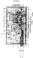
- Fig. 1 is a plan view showing a printer and a printing system according to a first embodiment of the present invention.
- Fig. 2 is an enlarged cross-section viewed from the direction of a side surface of the printer.
- Fig. 3 is a cross-section viewed from the discharge side of print paper of the printer.
- reference symbol A denotes a printer
- B denotes a digital camera
- the printer A contains in a cassette C a stack of print paper with photosensitive microcapsules applied thereto, and has a function to feed from the cassette C the print paper sheets one by one for printing.
- the digital camera B has a function to output an inputted image to an external device via a video output terminal (or a digital output terminal).
- the printer A and the digital camera B are connected via an interface cable.
- the mode where the printer A and the digital camera B are connected with each other is referred to as a printing system.
- image data stored in a memory of the digital camera B is transmitted to the printer A via the interface cable, and printed by the printer A on print paper P contained in the cassette C.
- the printer A is made up of the followings:
- the train of gears 16 transmits to the movable parts normal rotation and reverse rotation of the motor 15.
- the carriage 5 can be reciprocated only by continuously rotating the motor 15.
- the feed rollers 2a and 2b can slightly send the print paper P.
- the controller 17 controls the respective portions to operate for the initial adjustment. First, the controller 17 outputs a motor drive signal for driving the motor 15 to rotate counterclockwise. This makes the carriage 5 reciprocate.
- the controller 17 carries out operation to detect when a circulating pin 25 connecting a timing belt 6c with the carriage 5 comes to a home position a to stop the output of the motor drive signal.
- a signal as a result of reading a bar code C3 attached to the cassette C by a bar code sensor 22 is inputted to the controller 17 and the controller 17 carries out operation to specify the kind of the print paper P contained in the cassette C.
- the controller 17 selects from a ROM a program for setting the intensity or the time period of application of light from the light emitting diodes 8a, 8b, and 8c.
- the controller 17 controls the respective portions to operate for preparation for printing.
- the controller 17 carries out operation with regard to image data inputted from the digital camera B to make the data as an electric signal to make the light emitting diodes 8a, 8b, and 8c emit light.
- the controller 17 outputs a motor drive signal for drive the motor 15 rotate clockwise. This makes the pickup roller 1 and the feed rollers 2a and 2b rotate.
- the pickup roller 1 feeds the print paper P from the cassette C, and then, the feed roller 2a and the pinch rollers 3a pinch the print paper P to be fed.
- the controller 17 stops the output of the motor drive signal.
- the controller 17 controls the respective portions for operation to carry out printing. As described in the above, immediately after the pickup roller 1 feeds the print paper P from the cassette C, the controller 17 outputs a motor drive signal to drive the motor 15 to rotate counterclockwise, and at the same time, outputs an electric signal corresponding to the image data to the light emitting diodes 8a, 8b, and 8c.
- the electric signal to make the light emitting diodes 8a, 8b, and 8c emit the light is structured to be outputted synchronously with a signal as a result of reading by the linear sensor 21 of the graduation of the scale 23.
- the controller 17 finds by operation the amount of sending until a rear edge of the print paper P passes the feed roller 2b on the downstream side by counting the number of times the circulating pin 25 passes the home position, for example.
- the motor drive signal is adapted to be stopped when it is recognized that sending of a predetermined amount is completed.
- the print paper P used in the printer according to the present invention is called as photosensitive microcapsule type print paper.
- the print paper is formed by evenly applying photosensitive microcapsules having a diameter of about 4 microns to base paper, an image receiving layer including a color developing agent is applied on it, and then it is laminated by a polyester film.
- the microcapsules are merely minute capsules made of transparent gelatin. The microcapsules themselves transmit light, and have such an strength that they are collapsed by mechanical pressure of a print roller.
- Color developing material encapsulated in the microcapsules is transparent leuco dye which develop color when it is brought into contact with the image receiving layer including the color developing agent.
- the three primary colors of paint i.e., magenta (M), yellow (Y), and cyan (C) are prepared so as to correspond to the three primary colors of light, i.e., red (R), green (G), and blue (B).
- photo-curing material encapsulated in the microcapsules in combination with the color developing material material which is cured by light of specific wavelength i.e., light which is complementary to a color that appears when the light developing material is brought into contact with and reacts with the image receiving layer.
- print paper As special print paper, there are print paper for monochrome printing to which only one kind of photosensitive microcapsules are applied, and print paper for full color 256-gradation printing to which the three kinds of photosensitive microcapsules are applied, each of which can be broken down into print paper having high sensitivity and that for low sensitivity.
- the principle of developing of color of these kinds of special print paper is as follows.
- the region where the selected light is applied develops color which is mixture of M and Y, Y and C, or C and M.
- the region where the selected two kinds of light are applied develops color which corresponds to one among M, Y, or C.
- the region where none of the three kinds of light is applied develops color which corresponds to all of M, Y, and C, and thus, appears to be black.
- the tone, saturation, and lightness of the printing is adjusted by adjusting the intensity and the time period of application of the light.
- the photosensitive microcapsules and the image receiving layer are applied in advance to the print paper, it is not necessary to put together and process the film to which microcapsules are applied and a sheet paper to which the image receiving layer is applied during developing, as in the conventional case.
- the cassette C contains a stack of, that is, for example, ten sheets of the above-mentioned print paper P, and is detachably provided on the printer A.
- the cassette C is inserted into a cassette insert opening opened in a case 1 of the printer A.
- a protrusion on a slide door C1 on a top surface of the cassette C touches a claw 19a provided on the chassis 19 to open the slide door C1.
- a cassette retaining portion 19b provided on the chassis 2 retains the cassette C, a plate spring 26 bent like a mountain and provided on the chassis 2 enters from an opening at the bottom of the cassette C and lifts up a floor plate C2 of the cassette C such that the print paper P closely adheres to the pickup roller 1.
- the pickup roller 1 is a rubber roller and is rotatably attached to a shaft 29.
- the motor 15 rotates clockwise, the rotation of the shaft 29 is transmitted via a three-piece claw clutch 30 to the pickup roller 1, and thus, the pickup roller 1 rotates in a direction to feed the print paper P.
- the three-piece claw clutch 30 is made up of a driving claw 30a fixed to the shaft 29, an intermediate claw 30b rotatably put on the shaft 29 and having claw portions on both sides, and a driven claw 30c provided on the pickup roller 1.
- the print paper P moves in the direction of the insertion, gets in touch with the pickup roller 1, and attempts to rotate the pickup roller 1. Since, by adopting the above-mentioned structure, the three-piece claw clutch 30 has play of about one and a half circles with regard to rotation in the direction of feeding paper of the pickup roller 1, when the cassette C is inserted, the pickup roller 1 freely rotates.
- the shaft 29 rotates in about one and a half circles, the engagement of the driving claw 30a, the intermediate claw 30b, and the driven claw 30c makes the rotation of the shaft 29 is transmitted to the pickup roller 1.
- the feed rollers 2a and 2b are formed by putting and fixing a rubber cylindrical body on a steel shaft body.
- the pinch rollers 3a and 3b are made of plastic and their shafts and rollers are integrally formed.
- the pinch rollers 3a are formed of three independent rollers which are coaxially arranged below the feed roller 2a on the upstream side so as to freely rotate, and are pressed by a spring 27b so as to press the feed roller 2a.
- the pinch rollers 3b are arranged below the feed roller 2b on the downstream side and are pressed by the spring 27b so as to press the feed roller 2b.
- the belt putting around mechanism 6 is made up of a driving side timing pulley 6a and a driven side timing pulley 6b which are attached to vertical shafts 6e and 6d, respectively, provided on the carriage guide 4, and the timing belt 6c put around the pulleys 6a and 6b.
- the circulating pin 25 is provided on the timing belt 6c.
- the carriage 5 is provided so as to reciprocate in the scanning direction by being guided by the beam-like carriage guide 4.
- the circulating pin 25 provided on the timing belt 6c is inserted in an elongated hole 5a provided in the carriage 5.
- the carriage 5, the belt putting around mechanism 6, the rolling rollers 12a and 12b, the two sensors 21 and 22, and a part of the train of gears 16 are assembled to the carriage guide 4.
- an end portion of the carriage guide 4 closer to the driving side timing pulley 6a is engaged with and fixed to a rectangular hole (with no reference numeral), while the other end portion of the carriage guide 4 closer to the driven side timing pulley 6b is passed through an opening formed in the chassis 19 and is screwed to the chassis 2 by a screw 34.
- a plate 5b for attaching LEDs is provided on a lower portion of the carriage 5.
- the light emitting diodes 8a, 8b, and 8c are attached to the plate 5b for attaching LEDs. All of these light emitting diodes are light emitting diodes of high intensity.
- Green light emitted by the light emitting diodes 8b cures the photo-curing material encapsulated together with the color developing material which appears to be magenta. Further, there are three light emitting diodes 8c disposed which emit light of blue wavelength. Blue light emitted by the light emitting diodes 8c cures the photo-curing material encapsulated together with the color developing material which appears to be yellow. Light emitted by these light emitting diodes 8a, 8b, and 8c is applied to the print paper P via a pin hole in a plate 5c. It is to be noted that the number of the light emitting diodes may be varied depending on the required intensity of the light.
- the controller 17 carries out operation with respect to image data inputted from the digital camera B taking in consideration the phase shift of the light emitting diodes 8a, 8b, and 8c.
- the controller 17 also makes the light emitting diodes 8a, 8b, and 8c emit light according to the image data when the circulating pin 25 moves from the home position a to a position b , and from a position c to a position d .
- the emission of light is controlled to be synchronous with a signal as a result of reading by the linear sensor 21 of the graduation of the scale 23.
- the platen 9 and the rolling rollers 12a and 12b forms a pressurizing means for pressurizing a point of the print paper P with high pressure to collapse microcapsules applied to the print paper P.
- the platen 9 is disposed so as to be orthogonal to the sending direction of the print paper P, and its portion which is brought into contact with the rolling roller 12a is convex upward in section along the sending direction of the print paper P. Further, the platen 9 is lifted up in the direction of the rolling roller 12a by a spring 28 fixed to the chassis 19. The platen 9 is in point contact with the rolling roller 12a, and the pressure of the spring 28 is adjusted such that the contact pressure is about 800 g.
- Shaft portions at both ends of the two rolling rollers 12a and 12b are inserted in a hole longitudinally elongated and provided in a side surface portion of the carriage 5.
- Lifting force of the platen 9 lifted up by the spring 28 acts on the lower rolling roller 12a.
- the lifting force is received via the upper rolling roller 12b by the carriage guide 4. Therefore, when the carriage 5 moves, the upper rolling roller 12b is brought into contact with a lower surface of the carriage guide 4 and rolls, and the lower rolling roller 12a smoothly rolls without slippage with respect to the platen 9.
- the diameter of the lower rolling roller 12a is large while the diameter of the upper rolling roller 12b is small. While the diameters of the two rolling rollers 12a and 12b may be the same, if the diameter of the lower rolling roller 12a is larger, when the print paper P is not on the platen 9, noise caused when the lower rolling roller 12a transfers from a paper guide 11a or 11b described later to the platen 9 can be held down. It is to be noted that, for the purpose of holding down the noise, sound absorbing material (not shown) such as plate rubber or sponge is also bonded to the inner surfaces of the case 20.
- the paper guides 11a and 11b are provided on the upper surface of the platen 9 at both ends.
- the paper guides 11a and 11b are substantially as thick as the print paper P, and are, by a stopper not shown, retained such that the space between them is narrower by 2 - 3 mm than the width of the print paper P and are pressed by springs 10a and 10b in a direction of making narrower the space between them.
- ribs 11a' and 11b' are provided at edges on the upstream side of the paper guides 11a and 11b, respectively, such that, when the front edges of the print paper P abut against the ribs 11a' and 11b', they wedge open the space between the paper guides 11a and 11b.
- the paper guides 11a and 11b serve to control the position of the print paper P so as not to displace sideways due to contact resistance of the rolling roller 12a.
- the rolling roller 12a reciprocates along the carriage 5 and transfers in succession among the paper guide 11a, the platen 9, and the paper guide 11b. Therefore, when the print paper P is sent on the platen 9, the rolling roller 12a transfers in succession among the paper guide 11a, the print paper P, and the paper guide 11b.
- the rolling roller 12a is positioned away from the paper guide 11a or 11b.
- the train of gears 16 has a Geneva gear 16r described later, and a gear tooth of the Geneva gear 16r engages with a gear 16s during the rolling roller 12a is away from the paper guide 11a or 11b as described in the above.
- the rolling roller 12a except its both ends which do not step onto the print paper P linearly pressurizes, when the carriage reciprocates, the print paper P to collapse microcapsules which did not cure.
- the heater 14 heats the print paper P sent by the feed rollers 2a and 2b between the heater 14 and the plate spring 13.
- the color developing material in the collapsed microcapsules on the print paper P is brought into contact with the image receiving layer, and is further heated by the heater 14 to accelerate its developing of color.
- the heater 14 is provided on the downstream side of the feed roller 2b on the downstream side in this embodiment, since the print paper P is overheated if it is left sandwiched between the heater 14 and the plate spring 13, the heater 14 is preferably provided on the upstream side of the feed roller 2b on the downstream side.
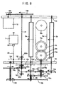
- the rotation of the motor 15 is transmitted to a shaft 31 by engagement of the gear 16a (the number of teeth: 12) with a gear 16b (the number of teeth: 84).
- the rotation of the shaft 31 is transmitted via a one-way clutch 32a to a gear 16c (the number of teeth: 30).
- the rotation of the gear 16c is transmitted by engagement of a gear 16d (the number of teeth: 20) with a gear 16e (the number of teeth: 30) to a bevel gear 16f (the number of teeth: 30) fixed coaxially with the gear 16e.
- the rotation of the bevel gear 16f is transmitted by its engagement with a bevel gear 16g (the number of teeth: 15) to a gear 16h (the number of teeth: 15) fixedly provided to the bevel gear 16g. Further, the rotation of the gear 16h is transmitted to a gear 16i (the number of teeth: 15).
- the gear 16i is provided integrally with the driving side timing pulley 6a of the belt putting around mechanism 6, and thus, running of the belt putting around mechanism 6 makes the carriage 5 reciprocate.
- the rotation of the motor 15 is transmitted to the shaft 31 by engagement of the gear 16a with the gear 16b.
- the rotation of the shaft 31 is transmitted via a one-way clutch 32b to a gear 16j (the number of teeth: 12).
- the rotation of the gear 16j is transmitted by its engagement with a gear 16k (the number of teeth: 42) to the shaft 29 of the pickup roller 1.
- the rotation of the shaft 31 is transmitted via a one-way clutch 32c to a gear 16l (the number of teeth: 19).
- the rotation of the gear 161 is transmitted by engagement of a gear 16m (the number of teeth: 31), a gear 16n (the number of teeth: 19), and a gear 16o (the number of teeth: 31) to the feed roller 2a fixed coaxially with the gear 16m and to the feed roller 2b fixed coaxially with the gear 16o.
- the controller 17 when an instruction signal to rapidly send the print paper is inputted, the controller 17 outputs a drive signal of the motor 15 such that power is transmitted by this second power transmission path until discharge of the print paper is completed.
- the motor 15 again rotates counterclockwise, rotational force is always transmitted to the belt putting around mechanism 6 to continue the reciprocation of the carriage 5.
- the function of the train of gears 16 for transmitting the rotational force to the belt putting around mechanism 6 is the same as in the case of the first power transmission path described in the above (1).
- the power transmission path for transmitting the rotational force to the belt putting around mechanism 6 is not described, and a third power transmission path for transmitting the rotation of the motor 15 to the pickup roller 1 and to the feed rollers 2a and 2b every time the carriage 5 goes to an end and makes a U-turn is described.
- the rotation of the motor 15 is transmitted to the shaft 31 by engagement of the gear 16a and the gear 16b.
- the rotation of the shaft 31 is transmitted via the one-way clutch 32a to a gear 16p (the number of teeth: 12).
- the rotation of the gear 16p is transmitted by its engagement with a gear 16q (the number of teeth: 30) to the Geneva gear 16r (the number of tooth: 1) fixed coaxially with the gear 16q.
- the rotation of the Geneva gear 16r is transmitted to the gear 16s (the number of teeth: 18).
- the Geneva gear 16r since the Geneva gear 16r has only one tooth, every time the Geneva gear 16r rotates in a circle, the gear 16s rotates by an angle for one of its teeth.
- the continuous rotation of the Geneva gear 16r is converted into intermittent rotation of the gear 16s.
- the intermittent rotation of the gear 16s is transmitted to a gear 16t (the number of teeth: 12) fixed coaxially with the gear 16s.
- the intermittent rotation of the gear 16t is transmitted by its engagement with a gear 16u (the number of teeth: 38) to the gear 16n via a one-way clutch 32d provided between a shaft portion of the gear 16u and a shaft hole of the gear 16n.
- the intermittent rotation of the gear 16n is transmitted by engagement of the gear 16m with the gear 16o to the feed roller 2a fixed coaxially with the gear 16m and to the feed roller 2b fixed coaxially with the gear 16o. In this way, every time the carriage 5 goes to an end and makes a U-turn, the feed rollers 2a and 2b rotates by a small angle to slightly send the print paper P.
- the train of gears 16 is further described.
- the train of gears 16 is provided with the pair of the driving side bevel gear 16f and the driven side bevel gear 16g which are engaged with each other at a power transmission branch portion for transmitting the rotational force to the belt putting around mechanism 6.
- the driven side bevel gear 16g can be unmovably assembled coaxially with the driving side timing pulley 6a.
- the driving side bevel gear 16f can not be firmly assembled to the shaft since it is in proximity to other gears.
- a bracket 33 for preventing bevel gear movement is provided on the chassis 19 so as to be in contact with a back surface of the driving side bevel gear 16f, such that the driving side bevel gear 16f is prevented from coming out of the shaft due to reaction force when it transmits the rotation to the driven side bevel gear 16g.
- the motor 15 rotates counterclockwise.
- the rotation of the motor 15 is transmitted via the first power transmission path of the train of gears 16 to the belt putting around mechanism 6.
- Running of the belt putting around mechanism 6 makes the carriage 5 reciprocate.
- the bar code sensor 22 reads the bar code C3 attached to the cassette C to specify the kind of the print paper P contained in the cassette C.
- the information with regard to the kind of the print paper specified here is used during printing to control the intensity or the time period of emission of light emitted from the light emitting diodes 8a, 8b, and 8c. Since the position of the carriage 5 is always detected by the linear sensor 21, when the carriage 5 returns to the home position, that state is detected and the rotation of the motor 15 is stopped.
- the motor 15 rotates clockwise.
- the rotation of the motor 15 is transmitted via the second power transmission path of the train of gears 16 to the pickup roller 1 and the feed rollers 2a and 2b.
- the pickup roller 1 feeds the print paper P from the cassette C.
- the fed print paper P is pinched by the feed roller 2a and the pinch rollers 3a and further fed.
- the paper sensor 24 detects the front edge of the print paper P, the rotation of the motor 15 is stopped.
- the motor 15 rotates counterclockwise again.
- the rotation of the motor 15 is transmitted via the first power transmission path of the train of gears 16 to the belt putting around mechanism 6.
- Running of the belt putting around mechanism 6 makes the carriage 5 reciprocate.
- the rotation of the motor 15 is transmitted via the third power transmission path of the train of gears 16 to the pickup roller 1 and the feed rollers 2a and 2b.
- the light emitting diodes 8a, 8b, and 8c apply light to the print paper P correspondingly to the image data to form a latent image on the print paper.
- the rolling roller 12a linearly pressurizes the print paper P to collapse the microcapsules which were not cured, thereby carrying out developing.
- the heater 14 heats the print paper P between the heater 14 and the plate spring 13.
- the color developing material in the collapsed microcapsules on the print paper P is brought into contact with the image receiving layer, and is further heated by the heater 14 to accelerate its developing of color.
- Fig. 7 is a sectional view of the printer taking along the same line as that in Fig. 3.
- the printer of the second embodiment differs from the printer of the first embodiment in that, while the printer of the first embodiment has the paper guides 11a and 11b, the printer of the second embodiment does not have the paper guides 11a and 11b but has a stopper 37 for restricting a rise of the platen 9.
- space g between the platen 9 and the rolling roller 12a is about a half of thickness t of the print paper P. Accordingly, even the print paper P is not on the platen 9, the rolling roller 12a is not brought into contact with the platen 9. Further, when the print paper P is on the platen 9, the difference in height when the rolling roller 12a steps onto the print paper P is about a half of the thickness of the print paper P, and since the shock at stepping onto the print paper P is small, the rolling roller 12a does not jump.
- the function to pressurize the print paper P is the same as that in the first embodiment described in the above.
- the stopper 37 is a protrusion provided so as to hang down from the carriage guide 4, it may be a screw or the like attached to the carriage guide 4. Further, the stopper may be provided on the side of the platen.
- the printer as the second embodiment is completely the same as the structure shown in Figs. 1 to 6 except that it does not have the paper guides 11a and 11b but it has the stopper 37 for restricting a rise of the platen 9, and thus, no additional drawing is prepared except Fig. 7.
- Fig. 8A is a partial enlarged sectional view illustrating the state of contact of the carriage and the carriage guide.
- Fig. 8B is a sectional view taken along the line IVb-IVb of Fig. 8A
- Fig. 8C is a sectional view taken along the line IVc-IVc of Fig. 8A.
- a carriage guide 4' is provided like a channel with highly accurate straightness, and ribs 4a and 4b on both sides are held by channel portions 5g and 5h on both sides of a carriage 5'.
- Abrasion resistant coating with a small coefficient of friction such as Teflon, fluorine contained resin, or the like is formed on sliding surfaces of one rib 4a of the carriage guide 4' and of one channel portion 5g of the carriage 5', and these surfaces are slidably in contact with each other.
- Abrasion resistant coating with a small coefficient of friction such as Teflon, fluorine contained resin, or the like is also formed on a side surface of the other rib 4b of the carriage guide 4'.
- a gap is provided between the rib 4b and the other channel portion 5h of the carriage 5' facing the rib 4b.
- a plate spring 10 made of stainless steel and bent like two mountains is fixed to the channel portion 5h and is inserted in the gap. Since the plate spring 10 is slidably in contact with the surfaces forming the gap, the rattle of the carriage 5' in the direction orthogonal with the scanning direction is absorbed.
- abrasion resistant coating with a small coefficient of friction such as Teflon, fluorine contained resin, or the like is also formed on a lower surface of the carriage guide 4'.
- a groove is dug in a surface of the carriage 5' facing the lower surface of the carriage guide 4', and a plate spring 11 made of stainless steel is attached there. Since the plate spring 11 is slidably in contact with the carriage guide 4', the vertical rattle of the carriage 5' is absorbed.
- steps are taken with regard to both the rattle in the direction orthogonal with the scanning direction and the rattle in the vertical direction, it may be structured to take steps with regard to either of the two as the need arises.
- a printer as a fourth embodiment of the present invention is described.
- the present embodiment is to attempt to make simpler bearings of the pinch rollers.
- Fig. 9A is a plan view of a supporting structure portion of pinch rollers.
- Fig. 9B is a perspective view of the bearing portions of the pinch rollers.
- Fig. 9C is a perspective view of a spring plate made of metal.
- the pinch rollers are formed of the first pinch rollers 3a and the second pinch rollers 3b each of which is formed by disposing independent three roller coaxially with each other.
- the shaft and the roller is integrally formed.
- Structure of the pinch rollers 3a and 3b is the same as that of the first embodiment. These pinch rollers 3a and 3b are supported by bearing portions 35a and plate spring receiving portions 27a1 and 27b1.
- the bearing portions 35a are, as shown in Fig. 9B, provided with notches for bearing at tips of peninsula-shaped portions 35 lifted up from a bottom surface portion of the chassis 19.
- the plate spring receiving portions 27a1 and 27b1 are, as shown in Fig. 9C, formed by bending horizontally upper end portions of peninsula-shaped plate springs 27a and 27b lifted up from a spring plate member 27 made of metal and further bending the horizontal portions.
- the spring plate member 27 made of metal is further provided with slits through which the bearing portions 35a pierce.
- the spring plate member 27 made of metal is put on the bottom surface portion of the chassis 19 with the bearing portions 35a piercing the slits.
- the respective pinch rollers 3a and 3b are supported by the bearing portions 35a and the plate spring receiving portions 27a1 and 27b1.
- the respective pinch rollers 3a and 3b are supported being pressed upward by the plate spring receiving portions 27a1 and 27b1.
- a printer as a fifth embodiment of the present invention is described.
- the present embodiment is to attempt to assemble easier the bearings of the pickup roller and of the feed rollers.
- Fig. 10A is a partial sectional view illustrating a structure of attaching the shaft 29 of the pickup roller 1
- Fig. 10B is a partial sectional view illustrating a structure of attaching shafts 2a1 and 2b1 of the feed rollers 2a and 2b
- Fig. 10C is a perspective view of a cylindrical bearing 36 used in these bearing structures.
- the cylindrical bearing 36 shown in Fig. 10C is put on the shaft 29 of the pickup roller 1 and on the shafts 2a1 and 2b1 of the feed rollers 2a and 2b, respectively. Further, the cylindrical bearings 36 are inserted into bearing containing portions provided in the chassis 19.
- the cylindrical bearing 36 is made by molding plastic.
- the cylindrical bearing 36 has a flange 36a in contact with the chassis 19, and a pair of L-shaped claws 36b.
- a groove is formed in a circumferential direction at both ends of the shaft 29 or the shafts 2a1 and 2b1, and the claws 36b are attached so as to fit into the groove and so as not to move in the axial direction. Therefore, when the cylindrical bearings 36 are attached to the chassis 19, the shaft 29 or the shafts 2a1 and 2b1 are attached so as not to move in the axial direction.
- the claws 36b of the cylindrical bearing 36 can be opened to some extent by being flexed. Therefore, when the shaft 29 or the shafts 2a1 and 2b1 are attached to the chassis 19, first, the shaft is inserted into the bearing containing portion in the chassis without the claws 36b being fitted into the groove in the shaft and with the cylindrical bearing 36 being slided inward of the shaft, and then, the cylindrical bearing 36 is inserted into the bearing containing portion, and the claws 36b are made to fit into the groove in the shaft for fixing.
- a cylindrical bearing having only the flange 36a may be used instead of the cylindrical bearing structured as described in the above.
- the end of the shaft on the side where the cylindrical bearing having only the flange 36a is attached is structured to have a difference in diameter.
- Fig. 11 is a plan view illustrating a printer as a sixth embodiment of the present invention.
- the platen 9 is axially supported such that its end portion 9a closer to the motor 15 rotates or swings in a plane vertical to the chassis 19.
- a cam-follower 9c extends from the other end portion 9b opposite to the motor 15, and presses a cam 38 provided integrally with the Geneva gear 16r from below. When the cam 38 presses down the cam-follower 9c, the platen 9 also goes down, and thus, the platen 9 goes away from the rolling roller 12a.
- the Geneva gear 16r acts to send the print paper P.
- the cam 38 presses down the cam-follower 9c to make the platen 9 go down.
- the point where the platen 9 goes is set to be, for example, 5 mm before the end portion.
- the cam 38 is released from pressing down the cam-follower 9c, and the platen 9 pressed from below by the spring 28 goes up. In this way, the carriage 9 is adapted to go down when it makes a U-turn in its reciprocation.
- an image can be developed by forming a latent image by applying light over print paper with photosensitive microcapsules applied thereto so as to correspond to image data inputted from the external and applying high pressure to the print paper with the latent image formed thereon thus collapsing microcapsules and making color developing material in the collapsed microcapsules in contact with image receiving layer.
- a film with microcapsules applied thereto and a sheet paper with an image receiving layer applied thereto are laminated to each other, it is not necessary to, as in a conventional printer, supply and wind separately a film with microcapsules applied thereto and a sheet paper with an image receiving layer applied thereto, and thus, a printer can be ultraminiaturized to be palm top.
- a pressurizing means for developing print paper with a latent image formed thereon is a rolling roller provided on a carriage and the rolling roller pressurizes print paper during the carriage reciprocates. Since the pressurization is carried out via point contact, even if large force does not act on the pressurizing means itself, the print paper can be pressurized with sufficiently high pressure. This makes it enough for a supporting structure of the printer to bear only a light load, which also makes it possible to miniaturize the printer.
- a cassette for containing print paper is provided, the cassette is provided with a code indicating the kind of the print paper such as photosensitive characteristics of the print paper, the code is read by a sensor, and emission of light applied to the print paper is controlled based on the information read with regard to the print paper. Therefore, with the printer, even if all the print paper in the cassette is not spent, the cassette can be freely exchanged for printing.
- a printer according to the present invention is provided with a heating means for heating print paper during developing. Since reaction of the color developing material in the microcapsules with the image receiving layer is accelerated by heating, the developing time can be shortened.
- a printer according to the present invention is provided with paper guides which is substantially as thick as the print paper for sandwiching and sending the print paper. Therefore, even if the rolling roller comes out of the print paper and again steps onto the print paper, since the rolling roller steps onto and steps off the paper guides, an impact due to pressurization is not applied to the print paper, and thus, blur of an image can be prevented and noise caused during printing can be suppressed.
- a printer according to the present invention is structured such that, when the print paper is not on the platen, the space between the pressure roller and the platen is about a half of the thickness of the print paper. Therefore, when the print paper is not on the platen, since the rolling roller is away from the platen, there is no noise caused by the rolling of the rolling roller.
- a printer according to the present invention is provided with two rolling rollers. Therefore, the two rolling rollers smoothly roll, high-speed movement of the rolling rollers can be secured, and in particular, when the diameter of a rolling roller which is brought into contact with the print paper is larger, noise caused when this rolling roller transfers from the print roller to a paper guide and the like can be suppressed further.
- a printer according to the present invention adopts bevel gears in a train of gears for driving the carriage, and the back surface of a driving side bevel gear is supported by a bracket for preventing bevel gear movement. Therefore, even in case the print paper is caught on the carriage and the carriage which has been moving at a high speed comes to a sudden stop, the bevel gears do not disengage, and failure of the power transmitting portion can be avoided.
- the carriage guide is assembled to the chassis after parts are assembled to the carriage guide in advance. This can make easier the assembling of the printer, and can make lower the manufacturing cost.
- pinch rollers are made of plastic material. Therefore, the sliding characteristics of the pinch rollers with respect to the print paper are improved, the print paper can be easily put between the feed rollers and the pinch rollers, and therefore, the print paper can be sent smoothly.
- the carriage is pressed against the carriage guide by a plate spring. Therefore, the rattle in the direction orthogonal with the scanning direction of the carriage or the rattle in the vertical direction can be eliminated, the carriage can be positioned precisely, and thus, lowering of the quality of an image can be prevented.
- shafts of the pinch rollers are borne by bearing portions lifted up from the chassis and are pressed upward by plate springs lifted up from a plate spring member. Further, the shafts of the pickup roller and the feed rollers are supported by the chassis via cylindrical bearings each having a flange and claws extending therefrom. This can make the structure of the printer simpler, can decrease the number of parts, and can decrease the manufacturing cost.
Landscapes
- Physics & Mathematics (AREA)
- Optics & Photonics (AREA)
- Health & Medical Sciences (AREA)
- General Health & Medical Sciences (AREA)
- Toxicology (AREA)
- General Physics & Mathematics (AREA)
- Printers Or Recording Devices Using Electromagnetic And Radiation Means (AREA)
- Photosensitive Polymer And Photoresist Processing (AREA)
- Photographic Developing Apparatuses (AREA)
Applications Claiming Priority (9)
| Application Number | Priority Date | Filing Date | Title |
|---|---|---|---|
| JP15271997 | 1997-06-10 | ||
| JP152719/97 | 1997-06-10 | ||
| JP15271997 | 1997-06-10 | ||
| JP32648697 | 1997-11-27 | ||
| JP326486/97 | 1997-11-27 | ||
| JP32648697 | 1997-11-27 | ||
| JP102890/98 | 1998-04-14 | ||
| JP10289098A JP3114014B2 (ja) | 1997-06-10 | 1998-04-14 | 感光型マイクロカプセルを塗布したプリンタ用紙を用いるプリンタ、プリントシステム、及びプリント方法 |
| JP10289098 | 1998-04-14 |
Publications (2)
| Publication Number | Publication Date |
|---|---|
| EP0884646A2 true EP0884646A2 (fr) | 1998-12-16 |
| EP0884646A3 EP0884646A3 (fr) | 1999-09-15 |
Family
ID=27309824
Family Applications (1)
| Application Number | Title | Priority Date | Filing Date |
|---|---|---|---|
| EP98304615A Withdrawn EP0884646A3 (fr) | 1997-06-10 | 1998-06-10 | Imprimante, système d'impression ainsi qu'une méthode d'impression utilisant du papier comprenant des microcapsules photosensibles |
Country Status (4)
| Country | Link |
|---|---|
| US (1) | US6229558B1 (fr) |
| EP (1) | EP0884646A3 (fr) |
| JP (1) | JP3114014B2 (fr) |
| KR (1) | KR19990006854A (fr) |
Cited By (2)
| Publication number | Priority date | Publication date | Assignee | Title |
|---|---|---|---|---|
| EP1168076A3 (fr) * | 2000-06-19 | 2003-01-02 | Eastman Kodak Company | Dispositif de formation d'image et méthode pour traiter un matériau photosensible contenant des microcapsules |
| EP1554633A4 (fr) * | 2002-10-02 | 2009-12-02 | Cycard Technologies Inc | Procede et systeme d'impression de cartes |
Families Citing this family (26)
| Publication number | Priority date | Publication date | Assignee | Title |
|---|---|---|---|---|
| JP3397617B2 (ja) | 1997-01-29 | 2003-04-21 | ペンタックス株式会社 | 回転伝達機構及びそれを用いた双眼鏡 |
| EP1312554B1 (fr) | 1999-11-11 | 2005-01-12 | Seiko Epson Corporation | Appareil de formation d'images |
| US7004652B2 (en) * | 2000-05-23 | 2006-02-28 | Silverbrook Research Pty Ltd | Printer for accommodating varying page thickness |
| ATE309102T1 (de) * | 2000-05-24 | 2005-11-15 | Silverbrook Res Pty Ltd | Sensor für die papierdicke in einem printer |
| ES2351206T3 (es) | 2001-02-27 | 2011-02-01 | Dolby Laboratories Licensing Corporation | Dispositivo de visualización de alta relación de contraste dinámico. |
| KR100422005B1 (ko) * | 2001-11-26 | 2004-03-11 | 삼성전자주식회사 | 용지 공급롤러 및 그 제조방법 |
| AUPS047602A0 (en) * | 2002-02-13 | 2002-03-07 | Silverbrook Research Pty. Ltd. | Methods and systems (ap67) |
| EP1485904B1 (fr) | 2002-03-13 | 2012-08-29 | Dolby Laboratories Licensing Corporation | Dispositifs d'affichage a plage dynamique elevee |
| US6809751B2 (en) * | 2002-10-02 | 2004-10-26 | Cycard Technologies, Inc. | Card printing system and method |
| JP4232549B2 (ja) * | 2003-06-19 | 2009-03-04 | ソニー株式会社 | 信号処理装置、信号処理方法、記録制限装置及び記録制限方法 |
| US6816240B1 (en) | 2003-07-17 | 2004-11-09 | Eastman Kodak Company | Image forming device having a photobleach system |
| US7008123B2 (en) * | 2003-11-25 | 2006-03-07 | Eastman Kodak Company | Image forming device having a brush type processing member |
| US6963392B1 (en) | 2004-05-21 | 2005-11-08 | Eastman Kodak Company | Image-forming device having a belt type processing member with micro-features |
| US20050285927A1 (en) * | 2004-06-23 | 2005-12-29 | Eastman Kodak Company | Image forming device and an exposure member for the device |
| US20060029387A1 (en) * | 2004-08-09 | 2006-02-09 | Eastman Kodak Company | Pressure development apparatus having a pressure roller with a non-metallic layer |
| US20060092400A1 (en) * | 2004-10-29 | 2006-05-04 | Eastman Kodak Company | Printing system for use with microencapsulated media |
| US20070019180A1 (en) * | 2005-07-19 | 2007-01-25 | Eastman Kodak Company | Image-forming device having brush/drum processor |
| US20070053686A1 (en) * | 2005-09-07 | 2007-03-08 | Eastman Kodak Company | Image-forming device having an exposing/processing platen |
| US8496411B2 (en) | 2008-06-04 | 2013-07-30 | T & B Structural Systems Llc | Two stage mechanically stabilized earth wall system |
| US8632278B2 (en) | 2010-06-17 | 2014-01-21 | T & B Structural Systems Llc | Mechanically stabilized earth welded wire facing connection system and method |
| US20090322800A1 (en) | 2008-06-25 | 2009-12-31 | Dolby Laboratories Licensing Corporation | Method and apparatus in various embodiments for hdr implementation in display devices |
| US9605402B2 (en) | 2009-01-14 | 2017-03-28 | Thomas P. Taylor | Retaining wall soil reinforcing connector and method |
| US8632279B2 (en) | 2010-01-08 | 2014-01-21 | T & B Structural Systems Llc | Splice for a soil reinforcing element or connector |
| US8393829B2 (en) | 2010-01-08 | 2013-03-12 | T&B Structural Systems Llc | Wave anchor soil reinforcing connector and method |
| US8632280B2 (en) | 2010-06-17 | 2014-01-21 | T & B Structural Systems Llc | Mechanically stabilized earth welded wire facing connection system and method |
| US8734059B2 (en) | 2010-06-17 | 2014-05-27 | T&B Structural Systems Llc | Soil reinforcing element for a mechanically stabilized earth structure |
Citations (2)
| Publication number | Priority date | Publication date | Assignee | Title |
|---|---|---|---|---|
| US5229585A (en) | 1991-02-19 | 1993-07-20 | Minnesota Mining And Manufacturing Company | Film cartridge bar code scanner and controller for a digital imaging system |
| US5481657A (en) | 1992-11-25 | 1996-01-02 | Minnesota Mining And Manufacturing Company | Multi-user digital laser imaging system |
Family Cites Families (20)
| Publication number | Priority date | Publication date | Assignee | Title |
|---|---|---|---|---|
| US4613246A (en) * | 1984-01-31 | 1986-09-23 | Brother Kogyo Kabushiki Kaisha | Printer with mounting structure for print head |
| JPS6275942A (ja) | 1985-09-27 | 1987-04-07 | Nec Home Electronics Ltd | 光ヘツド |
| US4782365A (en) * | 1985-11-05 | 1988-11-01 | Fuji Photo Film Co., Ltd. | Photographic printing apparatus and paper magazine for use therewith |
| JPS62290561A (ja) * | 1986-06-10 | 1987-12-17 | Seiko Instr & Electronics Ltd | カラ−プリンタ |
| JPH0818450B2 (ja) * | 1987-08-08 | 1996-02-28 | 三菱電機株式会社 | サ−マルプリンタ |
| JPH01113751A (ja) | 1987-10-27 | 1989-05-02 | Sony Corp | 現像装置 |
| JPH01185544A (ja) | 1988-01-18 | 1989-07-25 | Seiko Epson Corp | 画像形成装置 |
| US5060011A (en) * | 1988-04-28 | 1991-10-22 | Brother Kogyo Kabushiki Kaisha | Image recording apparatus |
| JPH0262275A (ja) * | 1988-08-30 | 1990-03-02 | Brother Ind Ltd | 記録装置 |
| US5036266A (en) * | 1989-01-17 | 1991-07-30 | Tektronix, Inc. | Mass velocity controller |
| US5049902A (en) | 1989-10-17 | 1991-09-17 | The Mead Corporation | System for recording an image |
| JPH03140621A (ja) | 1989-10-23 | 1991-06-14 | Brother Ind Ltd | プリンタのキャリッジ軸受機構 |
| JPH03235945A (ja) | 1990-02-13 | 1991-10-21 | Brother Ind Ltd | 画像形成装置 |
| JPH05204120A (ja) | 1991-02-19 | 1993-08-13 | Seiko Epson Corp | 画像形成装置 |
| JPH04318546A (ja) * | 1991-04-17 | 1992-11-10 | Brother Ind Ltd | 画像形成装置 |
| JPH06328781A (ja) * | 1993-05-25 | 1994-11-29 | Minolta Camera Co Ltd | 光プリンタ |
| JP3140621B2 (ja) | 1993-09-28 | 2001-03-05 | 株式会社日立製作所 | 分散ファイルシステム |
| JPH08272236A (ja) | 1995-03-30 | 1996-10-18 | Fuji Xerox Co Ltd | 画像形成装置 |
| US5550627A (en) | 1995-04-06 | 1996-08-27 | Cycolor Imaging, Inc. | Exposure and pressure applicator device for printing an image |
| JPH0969960A (ja) * | 1995-09-01 | 1997-03-11 | Brother Ind Ltd | 印刷出力装置 |
-
1998
- 1998-04-14 JP JP10289098A patent/JP3114014B2/ja not_active Expired - Fee Related
- 1998-06-09 US US09/094,038 patent/US6229558B1/en not_active Expired - Fee Related
- 1998-06-10 EP EP98304615A patent/EP0884646A3/fr not_active Withdrawn
- 1998-06-10 KR KR1019980021569A patent/KR19990006854A/ko not_active Withdrawn
Patent Citations (2)
| Publication number | Priority date | Publication date | Assignee | Title |
|---|---|---|---|---|
| US5229585A (en) | 1991-02-19 | 1993-07-20 | Minnesota Mining And Manufacturing Company | Film cartridge bar code scanner and controller for a digital imaging system |
| US5481657A (en) | 1992-11-25 | 1996-01-02 | Minnesota Mining And Manufacturing Company | Multi-user digital laser imaging system |
Cited By (2)
| Publication number | Priority date | Publication date | Assignee | Title |
|---|---|---|---|---|
| EP1168076A3 (fr) * | 2000-06-19 | 2003-01-02 | Eastman Kodak Company | Dispositif de formation d'image et méthode pour traiter un matériau photosensible contenant des microcapsules |
| EP1554633A4 (fr) * | 2002-10-02 | 2009-12-02 | Cycard Technologies Inc | Procede et systeme d'impression de cartes |
Also Published As
| Publication number | Publication date |
|---|---|
| JPH11216909A (ja) | 1999-08-10 |
| KR19990006854A (ko) | 1999-01-25 |
| EP0884646A3 (fr) | 1999-09-15 |
| US6229558B1 (en) | 2001-05-08 |
| JP3114014B2 (ja) | 2000-12-04 |
Similar Documents
| Publication | Publication Date | Title |
|---|---|---|
| EP0884646A2 (fr) | Imprimante, système d'impression ainsi qu'une méthode d'impression utilisant du papier comprenant des microcapsules photosensibles | |
| JP2950414B2 (ja) | プリンタの用紙加圧力調節装置 | |
| JPS6135983A (ja) | 多色プリンタ | |
| US4611218A (en) | Thermal head positioning apparatus with ribbon cassette | |
| JP3000364B2 (ja) | 感光型マイクロカプセル方式のプリント装置及びこれを用いた画像処理システム | |
| JP3026210B1 (ja) | プリンタ及びプリントシステム | |
| JP3041609B2 (ja) | プリント装置、プリント装置と画像処理装置のシステム | |
| JP2000071517A (ja) | 感光型マイクロカプセルを塗布したプリンタ用紙を用いるプリンタ | |
| JP3018248B1 (ja) | 感光型マイクロカプセルを塗布したプリンタ用紙を用いるプリンタ、及びプリントシステム | |
| JPH01113751A (ja) | 現像装置 | |
| JPH03286880A (ja) | カラープリンタ | |
| KR19990082050A (ko) | 가압현상장치 및 기록장치 | |
| JP2000168138A (ja) | 圧力現像装置及びこれを用いたプリンタ並びにプリントシステム | |
| JP2611229B2 (ja) | 熱転写プリンタ | |
| JPS60165278A (ja) | 画像形成装置 | |
| JP2001030594A (ja) | インクリボンカセットの支持構造 | |
| GB2311493A (en) | Heat transfer printer | |
| HK1022749A (en) | Printing apparatus of photosensitive microcapsule type and image processing system using the same | |
| JPH11352594A (ja) | 記録装置 | |
| JPS63318857A (ja) | 記録装置 | |
| JP2001030592A (ja) | インクリボンカセットおよびこれを使用したシリアルヘッド型記録装置 | |
| JP2002292928A (ja) | 光プリンタ用印刷ヘッド機構 | |
| JP2001065660A (ja) | 往復搬送装置及びそれを備えた印刷装置 | |
| JPS6153078A (ja) | 感熱記録装置 | |
| KR20000067745A (ko) | 잉크 리본 집합체 및 이 잉크 리본 집합체를 사용하는 열전사프린터 |
Legal Events
| Date | Code | Title | Description |
|---|---|---|---|
| PUAI | Public reference made under article 153(3) epc to a published international application that has entered the european phase |
Free format text: ORIGINAL CODE: 0009012 |
|
| AK | Designated contracting states |
Kind code of ref document: A2 Designated state(s): DE FR GB |
|
| AX | Request for extension of the european patent |
Free format text: AL;LT;LV;MK;RO;SI |
|
| PUAL | Search report despatched |
Free format text: ORIGINAL CODE: 0009013 |
|
| AK | Designated contracting states |
Kind code of ref document: A3 Designated state(s): AT BE CH CY DE DK ES FI FR GB GR IE IT LI LU MC NL PT SE |
|
| AX | Request for extension of the european patent |
Free format text: AL;LT;LV;MK;RO;SI |
|
| 17P | Request for examination filed |
Effective date: 20000306 |
|
| AKX | Designation fees paid |
Free format text: DE FR GB |
|
| 17Q | First examination report despatched |
Effective date: 20000613 |
|
| TPAD | Observations by third parties |
Free format text: ORIGINAL CODE: EPIDOS TIPA |
|
| STAA | Information on the status of an ep patent application or granted ep patent |
Free format text: STATUS: THE APPLICATION IS DEEMED TO BE WITHDRAWN |
|
| 18D | Application deemed to be withdrawn |
Effective date: 20001024 |