EP0884695B1 - Bilderweiterungsverfahren und -Vorrichtung - Google Patents
Bilderweiterungsverfahren und -Vorrichtung Download PDFInfo
- Publication number
- EP0884695B1 EP0884695B1 EP98108557A EP98108557A EP0884695B1 EP 0884695 B1 EP0884695 B1 EP 0884695B1 EP 98108557 A EP98108557 A EP 98108557A EP 98108557 A EP98108557 A EP 98108557A EP 0884695 B1 EP0884695 B1 EP 0884695B1
- Authority
- EP
- European Patent Office
- Prior art keywords
- picture element
- adjacent
- black
- obliquely
- interest
- Prior art date
- Legal status (The legal status is an assumption and is not a legal conclusion. Google has not performed a legal analysis and makes no representation as to the accuracy of the status listed.)
- Expired - Lifetime
Links
Images


Classifications
-
- G—PHYSICS
- G06—COMPUTING OR CALCULATING; COUNTING
- G06T—IMAGE DATA PROCESSING OR GENERATION, IN GENERAL
- G06T5/00—Image enhancement or restoration
- G06T5/20—Image enhancement or restoration using local operators
- G06T5/30—Erosion or dilatation, e.g. thinning
Definitions
- This invention relates to a method and apparatus for carrying out image processing on a binary image signal, which is obtained from a computer, an image read-out apparatus, or the like.
- This invention particularly relates to a character pattern and line pattern thickening processing (hereinbelow referred to simply as the thickening processing) for thickening a character pattern and a line pattern in a binary image, which is represented by a digital signal.
- an image forming apparatus which expands a character pattern or a line pattern in a binary image by simply adding black picture elements to the upper position, the lateral position, and the oblique position with respect to a black picture element in the binary image.
- Such an image forming apparatus is proposed in, for example, Japanese Unexamined Patent Publication No. 6(1994)-152932.
- the technique proposed in Japanese Unexamined Patent Publication No. 6(1994)-152932 has the problems in that a blank region, which is to be kept as a blank, becomes black and is lost.
- the problems will be described hereinbelow with reference to Figures 18 and 19, which show an example of the thickening processing carried out on a binary image signal by the utilization of the proposed technique.
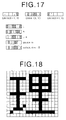
- Figure 18 is a matrix diagram showing an example of an original binary image to be subjected to thickening processing.
- Figure 19 is a matrix diagram showing a binary image, which is obtained from thickening processing carried out on the original image of Figure 18 by using an example of conventional technique (proposed in Japanese Unexamined Patent Publication No. 6(1994)-152932).
- black picture elements are simply added to the upper position, the left position, and the upper left position with respect to a black picture element in the original image. Therefore, in cases where the thickening processing is carried out with the proposed technique, a white picture element, which is surrounded by a plurality of black picture elements, and a white picture element, which is sandwiched between adjacent black picture elements, are converted into black picture elements. Accordingly, it often occurs that a region, which is to be recorded as a blank, becomes black and is lost. For example, the two lower blank regions among the four blank regions, which are defined by the three vertical black lines and the three horizontal black lines at the upper half of the right-hand radical of the Chinese character pattern in the original image shown in Figure 18, become black and are lost as illustrated in Figure 19.
- the blank region which is located between the left-hand radical and the right-hand radical of the Chinese character pattern, becomes black and is lost as illustrated in Figure 19.
- the problems occur in that the image becomes unsharp and hard to see and cannot be read.
- the character pattern in which the blank regions that are to be retained have become black and have been lost, cannot give a good aesthetic feeling to persons who see it.
- the thickness of a line can be changed such that a blank region may not become black and may not be lost.
- the proposed technique has the drawbacks in that very complicated discrimination processing must be carried out in order to discriminate the contours of character patterns and line patterns in a binary image.
- the primary object of the present invention is to provide an image thickening processing method, wherein a character pattern and a line pattern in a binary image are thickened with a simple processing, such that a blank region in the binary image, which blank region is to be retained, may be prevented from becoming black and being lost.
- Another object of the present invention is to provide an apparatus for carrying out the image thickening processing method.
- An image thickening processing method in accordance with the present invention wherein a thickening processing is carried out on a binary image made up of a plurality of black picture elements and white picture elements, which are adjacent to one another along vertical and horizontal directions , is characterized by setting each of the black picture elements as a black picture element of interest, detecting a vertically adjacent picture element, which is adjacent to said black picture element of interest along a single vertical direction, a horizontally adjacent picture element, which is adjacent to said black picture element of interest along a single horizontal direction, and an obliquely adjacent picture element, which is adjacent to all of said black picture element of interest, said vertically adjacent picture element, and said horizontally adjacent picture element, and setting each of the thus detected three adjacent picture elements as a black picture element only in cases where each of the thus detected three adjacent picture elements does not belong to a region, which is surrounded by a plurality of black picture elements and is to be recorded as a blank.
- the present invention provides an image thickening processing method, wherein a thickening processing is carried out on a binary image made up of a plurality of black picture elements and white picture elements, which are adjacent to one another along vertical and horizontal directions, the method comprising the steps of:
- thickening means all of the thickening of character patterns, the thickening of line patterns, and the like.
- the term “single vertical direction” as used herein means either one of the upward direction and the downward direction.
- the term “single horizontal direction” as used herein means either one of the rightward direction and the leftward direction.
- the term “setting as a black picture element” as used herein means that a picture element, which was a white picture element in the binary image before being processed, is altered into a black picture element, and a picture element, which was a black picture element in the binary image before being processed, is not altered.
- the vertically adjacent picture element is the region sandwiched between at least two black picture elements.
- the vertically adjacent picture element is the region, which was a blank in the binary image before being subjected to the thickening processing. Therefore, if the vertically adjacent picture element is altered into a black picture element in the thickening processing, the blank region will become black and is lost.
- the alteration of the vertically adjacent picture element into a black picture element is not carried out, and the blank region is retained even after the thickening processing. Specifically, only when the picture element, which is adjacent to the vertically adjacent picture element even further along the single vertical direction, is a white picture element, the vertically adjacent picture element is altered into a black picture element. In the same manner, in cases where the picture element, which is adjacent to the horizontally adjacent picture element even further along the single horizontal direction, (the next picture element but one to the black picture element of interest along the single horizontal direction) is a black picture element, the alteration of the horizontally adjacent picture element into a black picture element is not carried out. Only when the next picture element but one to the black picture element of interest along the single horizontal direction is a white picture element, the horizontally adjacent picture element is altered into a black picture element.
- the obliquely adjacent picture element is the region sandwiched between at least two black picture elements.
- the obliquely adjacent picture element is the region, which was a blank in the binary image before being subjected to the thickening processing.
- the blank region will become black and is lost. Accordingly, in such cases, the alteration of the obliquely adjacent picture element into a black picture element is not carried out, and the blank region is retained even after the thickening processing.
- the obliquely adjacent picture element is altered into a black picture element.
- a certain picture element which is adjacent to a black picture element in the original image, is set as a black picture element at least in cases where the aforesaid conditions for the certain picture element to be set as a black picture element for the thickening in accordance with a single black picture element, to which the certain picture element is adjacent, are satisfied.
- the aforesaid thickening processing is carried out with respect to the picture elements in the binary image before being subjected to the thickening processing, and is not carried out with respect to the picture elements after being subjected to the thickening processing.
- the thickening processing may be carried out simultaneously with respect to all picture elements. Alternatively, the thickening processing may be carried out successively with respect to the picture elements before being subjected to the thickening processing.
- the upward direction is employed as the single vertical direction
- the leftward direction is employed as the single horizontal direction
- the main scanning of the picture elements in the binary image is carried out along the rightward direction
- the sub-scanning of the picture elements in the binary image is carried out along the downward direction.
- the picture elements in the binary image are not processed all at once, and are successively set as a black picture element for the thickening.
- the present invention also provides an image thickening processing apparatus, wherein a thickening processing is carried out on a binary image made up of a plurality of black picture elements and white picture elements, which are adjacent to one another along vertical and horizontal directions, the apparatus comprising:
- each of the black picture elements is set as a black picture element of interest.
- the vertically adjacent picture element which is adjacent to the black picture element of interest along the single vertical direction
- the horizontally adjacent picture element which is adjacent to the black picture element of interest along the single horizontal direction
- the obliquely adjacent picture element which is adjacent to all of the black picture element of interest, the vertically adjacent picture element, and the horizontally adjacent picture element.
- Each of the thus detected three adjacent picture elements is set as a black picture element only in cases where each of the thus detected three adjacent picture elements does not belong to a region, which is surrounded by a plurality of black picture elements and is to be recorded as a blank.
- a character pattern and a line pattern in the binary image can be thickened, such that a blank region which is to be retained in the binary image may be prevented from becoming black and being lost. Accordingly, the blurring, or the like, of the printed image can be prevented.
- the processing with the image thickening processing method and apparatus in accordance with the present invention may be carried out before the printing operation is carried out. In this manner, a binary image, which has an appropriate thickness and is easy to see and read, can be printed.
- Figure 1 shows an example of an image, which is obtained from thickening processing carried out on an original image shown in Figure 18 by using the below-described image thickening processing method and apparatus in accordance with the present invention.
- an image, in which the lines constituting a character pattern have been thickened can be obtained such that a blank region to be retained, which became black and was lost with the technique proposed in Japanese Unexamined Patent Publication No. 6(1994)-152932, may not become black and may not be lost.
- FIG. 2 is a block diagram showing an embodiment of the image thickening processing apparatus in accordance with the present invention.
- the operator arbitrarily selects whether the thickening processing is or is not to be carried out, and information representing the results of the selection is fed into an image read-out apparatus 1.
- a binary image signal which has been detected by the image read-out apparatus 1 and fed out therefrom, is transmitted directly into a digital stencil printer 4 and used in an ordinary printing operation carried out by the digital stencil printer 4.
- the binary image signal which has been detected by the image read-out apparatus 1 is transmitted from the image read-out apparatus 1 into a storage device 2 and stored therein.
- Character patterns, line patterns, and the like, which are represented by the binary image signal stored in the storage device 2, are subjected to the thickening processing, which is carried out by a thickening means 3 connected to the storage device 2.
- a binary image signal, which has been obtained from the thickening processing, is overwritten on the binary image signal, which has been stored in the storage device 2.
- the binary image signal, which has been obtained from the thickening processing and is now stored in the storage device 2 is transmitted into the digital stencil printer 4.
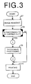
- FIGS 3, 4, 5, and 6 are flow charts showing control operation procedures in the image thickening processing carried out in the embodiment of Figure 2.
- the image read-out apparatus 1 reads out a given image and obtains the binary image signal representing the original image.
- a thickening judgment step S8 in accordance with the information representing the results of the selection made by the operator, a judgment is made as to whether the thickening processing is or is not to be carried out.
- a thickening processing step S9 is carried out, and a printing operation is carried out in a printing step S10 by the digital stencil printer 4.
- the thickening processing step S9 is not carried out, and a printing operation is carried out in the printing step S10 by the digital stencil printer 4.
- Figure 4 shows how the thickening processing is carried out in the thickening processing step S9.
- Figure 5 shows how a judgment matrix loading step S12 is carried out in the thickening processing step S9 shown in Figure 4.
- Figure 6 shows how processes 1, 2, and 3 shown in Figure 4 are carried out.
- Figure 7 shows an array of picture elements represented by a binary image signal, which has been obtained from the image read-out apparatus 1 and stored in the storage device 2.
- the array size along the main scanning direction (in this case, the horizontal direction) is represented by m
- the array size along the sub-scanning direction (in this case, the vertical direction) is represented by n.
- the spatial coordinate along the main scanning direction is represented by x
- the spatial coordinate along the sub-scanning direction is represented by y.
- 1 ⁇ x ⁇ m, and 1 ⁇ y ⁇ n the picture element value of the picture element, which is located at the spatial coordinates (x, y), is represented by d(x, y).
- the picture element value d(x, y) takes a value of 0 (representing white) or a value of 1 (representing black).
- Figure 8 shows a judgment matrix having a size of 3 ⁇ 3 picture elements, which is used in making a judgment as to whether a character pattern, a line pattern, or the like, is or is not to be thickened.
- Figure 8 shows the relationship among the positions of picture elements A, B, C, D, E, F, G, and H with the lower right picture element I being taken as a picture element of interest.
- means for forcibly converting the picture elements, which are located along the top row in the array of the picture elements represented by the binary image signal, and the picture elements, which are located along the left end column in the array of the picture elements, into white may be employed.
- a binary image signal loading step S11 the information representing the size, m, of the array of the picture elements, which are represented by the binary image signal, along the main scanning direction, the information representing the size, n, of the array of the picture elements along the sub-scanning direction, and the pieces of information, which represent the picture element values d(1, 1) through d(m, n), are loaded from the storage device 2 into the thickening means 3 (m ⁇ 3, n ⁇ 3).
- the picture elements, which are located along the top row in the array of the picture elements represented by the binary image signal, and the picture elements, which are located along the left end column in the array of the picture elements are white.
- each of the scanned picture elements is taken as the picture element of interest I in the judgment matrix shown in Figure 8, and the pieces of information representing the picture element values of the picture elements A through I, whose relative positions are defined in the judgment matrix, are loaded from the storage device 2.
- the picture element of interest I which is among the picture elements loaded in the judgment matrix loading step S12, is or is not black.
- processes 1, 2, and 3 described below are carried out.
- the judgment matrix loading step S12, the picture-element-of-interest judging step S13, and the processes 1, 2, 3 are repeated.
- the picture elements A, B, C, D, and G in the judgment matrix are located more outward than the array of the picture elements represented by the binary image signal, and therefore their values cannot be loaded from the storage device 2.
- the picture element values of the picture elements A, B, C, D, and G are forcibly set as being white (i.e., as a value of 0), and only the picture element values of the picture elements E, F, H, and I are loaded from the storage device 2.
- the picture elements A, B, and C in the judgment matrix are located more outward than the array of the picture elements represented by the binary image signal, and therefore their values cannot be loaded from the storage device 2.
- the picture element values of the picture elements A, B, and C are forcibly set as being white (i.e., as a value of 0), and only the picture element values of the picture elements D, E, F, G, H, and I are loaded from the storage device 2.
- the picture elements A, D, and G in the judgment matrix are located more outward than the array of the picture elements represented by the binary image signal, and therefore their values cannot be loaded from the storage device 2.
- the picture element values of the picture elements A, D, and G are forcibly set as being white (i.e., as a value of 0), and only the picture element values of the picture elements B, C, E, F, H, and I are loaded from the storage device 2.
- the binary image signal representing the entire image, which has been read out with the image read-out apparatus 1 may be stored.
- the read-out operation with the image read-out apparatus 1 and processes with the digital stencil printer 4 can be carried out in synchronization with each other, it is sufficient for only the minimum amount of the binary image signal, which is necessary for the thickening means 3, to be stored in the storage device 2.
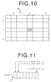
- Figure 10 shows a binary image signal 61 processed in this embodiment.
- the binary image signal 61 which represents a picture element array made up of n picture elements located along the sub-scanning direction and m' ⁇ 8 picture elements along the main scanning direction (n ⁇ 1, m' ⁇ 2), is transmitted from the image read-out apparatus 1 into the storage device 2.
- the binary image signal 61 is stored as m' ⁇ n number of two-dimensional array signals DATA(X, Y) 62.
- the two-dimensional array will hereinbelow be referred to as the "array signal.”
- the position along the main scanning direction is represented by X
- the position along the sub-scanning direction is represented by Y. In this case, 1 ⁇ X ⁇ m', and 1 ⁇ Y ⁇ n.
- Figure 11 shows the constitution of the array signal DATA(X, Y) 62.
- DATA(X, Y) has eight elements.
- An i'th element, as counted from the left, is represented by e(DATA(X, Y), i) and takes a value of 0 (representing white) or a value of 1 (representing black).
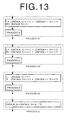
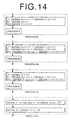
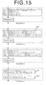
- FIGS 12, 13, 14, and 15 are flow charts showing the control procedures in this embodiment.
- the control procedures have nine subroutines, i.e. processes A1, A2, A3, B1, B2, B3, C1, C2, and C3.
- C2 is a principal process and is ordinarily executed most frequently. If only the process C2 is employed, it will occur that the array signal subjected to the judgment and processing falls more outward than the binary image signal 61. Therefore, the other processes are carried out as exceptional processes.
- the operation of DATA(X, Y)>>i represents a right shift of DATA(X, Y) by i bits, and e(DATA(X, Y), 1) through e(DATA(X, Y), i) are set as being white. In this case, 1 ⁇ i ⁇ 8.
- the operation of "+” with respect to the array signal represents the ORing of the elements of the array signal with each other.
- the operation of " ⁇ ” represents the ANDing of the elements of the array signal with each other.
- the operation of " - " represents the logical NOT of each element of the array signal.
- FIG 16 shows an example of execution of the step S21.
- the element indicated by the " ⁇ " mark is the one which has been altered into black by the step S21.
- An array signal 23 is the result obtained by carrying out the process 1, which is shown in Figure 6, simultaneously for eight picture elements.
- an array signal 24 is the result obtained by carrying out the process 2, which is shown in Figure 6, simultaneously for eight picture elements.
- the process 1 and the process 2 shown in Figure 6 are carried out simultaneously for eight picture elements.
- Figure 17 shows an example of execution of the step S22. As illustrated in Figure 17, in the step S22, the process 3 shown in Figure 6 is carried out simultaneously for eight picture elements.
- the array signal DATA(X, Y-1) with respect to the row, which is upper by one row along the sub-scanning direction, R1, and the array signal DATA(X, Y-2) with respect to the row, which is upper by two rows along the sub-scanning direction, R2, are used.
- exceptional processes A1, A2, and A3 are utilized.
- DATA(X, Y-2) and R2 are not present and therefore cannot be loaded.
- exceptional processes B1, B2, and B3 are utilized.
- This embodiment can be carried out by using a CPU controlled by a software.
- the processing unit in which the number of elements is eight, is used, and the thickening processing is carried out simultaneously for eight picture elements.
- the number of picture elements, which are processed simultaneously may be altered by altering the size of the processing unit. For example, in cases where a CPU having a 32-bit bus is used, the size of the processing unit may be set to be 32 bits (the number of elements: 32).
- This embodiment can also be carried out with a logic circuit and a memory. With this embodiment, since the processing is carried out simultaneously for a plurality of picture elements, the processing can be carried out quickly.
- a binary image obtained from a read-out apparatus such as an image scanner
- the image thickening processing method and apparatus in accordance with the present invention are also applicable when a binary image outputted from a computer, or the like, is subjected to the thickening processing.
Landscapes
- Physics & Mathematics (AREA)
- General Physics & Mathematics (AREA)
- Engineering & Computer Science (AREA)
- Theoretical Computer Science (AREA)
- Image Processing (AREA)
- Editing Of Facsimile Originals (AREA)
- Facsimile Image Signal Circuits (AREA)
- Controls And Circuits For Display Device (AREA)
- Dot-Matrix Printers And Others (AREA)
- Color, Gradation (AREA)
Claims (4)
- Bildverdünnungs-Verarbeitungsverfahren, bei dem eine Verdünnungsverarbeitung bezüglich eines binären Bildes durchgeführt wird, welches aus einer Mehrzahl von schwarzen Bildelementen und weißen Bildelementen besteht, die einander entlang einer vertikalen und einer horizontalen Richtung benachbart sind, umfassend die Schritte:i) Einstellen jedes der schwarzen Bildelemente als interessierendes schwarzes Bildelement,ii) Erfassen eines vertikal benachbarten Bildelements, welches dem interessierenden schwarzen Bildelement entlang einer einzelnen vertikalen Richtung benachbart ist, eines horizontal benachbarten Bildelements, welches dem interessierenden Bildelement entlang einer einzelnen horizontalen Richtung benachbart ist, und eines schräg benachbarten Bildelements, welches gleichzeitig dem vertikal benachbarten Bildelement, dem horizontal benachbarten Bildelement und dem interessierenden schwarzen Bildelement benachbart ist, undiii) Ausführen der Verdickungsverarbeitung durch:a) Einstellen des vertikal benachbarten Bildelements als ein schwarzes Bildelement nur in solchen Fällen, in denen ein Bildelement, welches dem vertikal benachbarten Bildelement noch weiter entlang der einzelnen vertikalen Richtung benachbart ist, als ein weißes Bildelement ermittelt wurde,b) Einstellen des horizontal benachbarten Bildelements als ein schwarzes Bildelement nur in solchen Fällen, in denen ein Bildelement, welches dem horizontal benachbarten Bildelement entlang der einzelnen horizontalen Richtung noch weiter benachbart ist, als ein weißes Bildelement ermittelt wurde, undc) Einstellen des schräg benachbarten Bildelements als ein schwarzes Bildelement nur in solchen Fällen, in denen sämtliche von folgenden Bildelementen als weißes Bildelement ermittelt wurden: ein Bildelement, welches dem schräg benachbarten Bildelement noch weiter entlang der einzelnen vertikalen Richtung benachbart ist, ein Bildelement, welches dem schräg benachbarten Bildelement noch weiter entlang der einzelnen horizontalen Richtung benachbart ist, und ein Bildelement, welches dem schräg benachbarten Bildelement schräg auf der Seite benachbart ist, die dem interessierenden schwarzen Bildelement abgewandt ist.
- Verfahren nach Anspruch 1, bei dem die einzelne vertikale Richtung die Aufwärtsrichtung ist, die einzelne horizontale Richtung die Richtung nach links ist, eine Hauptabtastung der Bildelemente in dem binären Bild in Richtung nach rechts durchgeführt wird, und eine Nebenabtastung der Bildelemente des binären Bilds in Abwärtsrichtung durchgeführt wird, wodurch die Verdickungsverarbeitung zum Einstellen des benachbarten Bildelements als ein schwarzes Bildelement in Bezug auf jedes interessierende schwarze Bildelement sukzessive durchgeführt wird.
- Bildverdickungs-Verarbeitungsvorrichtung, in der eine Verdickungsverarbeitung bezüglich eines Binärbilds durchgeführt wird, welches aus mehreren schwarzen Bildelementen und weißen Bildelementen besteht, die einander entlang einer vertikalen und einer horizontalen Richtung benachbart sind, wobei die Vorrichtung umfaßt:i) eine Beurteilungseinrichtung zumEinstellen jedes der schwarzen Bildelemente als interessierendes schwarzes Bildelement,Erfassen eines vertikal benachbarten Bildelements, welches dem interessierenden schwarzen Bildelement entlang einer einzelnen vertikalen Richtung benachbart ist, eines horizontal benachbarten Bildelements, welches dem interessierenden Bildelement entlang einer einzelnen horizontalen Richtung benachbart ist, und eines schräg benachbarten Bildelements, welches gleichzeitig dem vertikal benachbarten Bildelement, dem horizontal benachbarten Bildelement und dem interessierenden schwarzen Bildelement benachbart ist, undDurchführen von Beurteilungen dahingehend,a) ob ein Bildelement, welches dem vertikal benachbarten Bildelement noch weiter entlang der einzelnen vertikalen Richtung benachbart ist, ein weißes Bildelement ist oder nicht,b) ob ein Bildelement, welches dem horizontal benachbarten Bildelement noch weiter entlang der einzelnen horizontalen Richtung benachbart ist, ein weißes Bildelement ist oder nicht, undc) ob sämtliche Bildelemente von folgenden Bildelementen weiße Bildelemente sind oder nicht: ein Bildelement, welches dem schräg benachbarten Bildelement noch weiter entlang der einzelnen vertikalen Richtung benachbart ist, ein Bildelement, welches dem schräg benachbarten Bildelement entlang der einzelnen horizontalen Richtung noch weiter benachbart ist, und ein Bildelement, welches dem schräg benachbarten Bildelement auf derjenigen Seite benachbart ist, die dem interessierenden schwarzen Bildelement abgewandt ist, undii) eine Verdickungseinrichtung zuma) Einstellen des vertikal benachbarten Bildelements als ein schwarzes Bildelement nur in solchen Fällen, in denen ein Bildelement, welches dem vertikal benachbarten Bildelement noch weiter entlang der einzelnen vertikalen Richtung benachbart ist, als ein weißes Bildelement durch die Beurteilungseinrichtung ermittelt wurde,b) Einstellen des horizontal benachbarten Bildelements als ein schwarzes Bildelement nur in solchen Fällen, in denen ein Bildelement, welches dem horizontal benachbarten Bildelement entlang der einzelnen horizontalen Richtung noch weiter benachbart ist, als ein weißes Bildelement durch die Beurteilungseinrichtung ermittelt wurde, undc) Einstellen des schräg benachbarten Bildelements als ein schwarzes Bildelement nur in solchen Fällen, in denen sämtliche von folgenden Bildelementen als weißes Bildelement durch die Beurteilungseinrichtung ermittelt wurden: ein Bildelement, welches dem schräg benachbarten Bildelement noch weiter entlang der einzelnen vertikalen Richtung benachbart ist, ein Bildelement, welches dem schräg benachbarten Bildelement noch weiter entlang der einzelnen horizontalen Richtung benachbart ist, und ein Bildelement, welches dem schräg benachbarten Bildelement schräg auf der Seite benachbart ist, die dem interessierenden schwarzen Bildelement abgewandt ist.
- Vorrichtung nach Anspruch 3, bei der die Beurteilungseinrichtung die einzelne vertikale Richtung als die Aufwärtsrichtung einstellt, die einzelne horizontale Richtung als die Richtung nach links einstellt, eine Hauptabtastung der Bildelemente des binären Bildes entlang der Richtung nach rechts durchführt, eine Nebenabtastung der Bildelemente des binären Bilds entlang der Richtung nach unten durchführt, um dadurch sukzessive die Entscheidungen bezüglich jedes interessierenden schwarzen Bildelements zu treffen.
Applications Claiming Priority (3)
| Application Number | Priority Date | Filing Date | Title |
|---|---|---|---|
| JP12123397 | 1997-05-12 | ||
| JP121233/97 | 1997-05-12 | ||
| JP12123397A JP3684029B2 (ja) | 1997-05-12 | 1997-05-12 | 画像太線化処理方法および装置 |
Publications (2)
| Publication Number | Publication Date |
|---|---|
| EP0884695A1 EP0884695A1 (de) | 1998-12-16 |
| EP0884695B1 true EP0884695B1 (de) | 1999-10-27 |
Family
ID=14806215
Family Applications (1)
| Application Number | Title | Priority Date | Filing Date |
|---|---|---|---|
| EP98108557A Expired - Lifetime EP0884695B1 (de) | 1997-05-12 | 1998-05-11 | Bilderweiterungsverfahren und -Vorrichtung |
Country Status (4)
| Country | Link |
|---|---|
| US (1) | US6154575A (de) |
| EP (1) | EP0884695B1 (de) |
| JP (1) | JP3684029B2 (de) |
| DE (1) | DE69800035T2 (de) |
Families Citing this family (5)
| Publication number | Priority date | Publication date | Assignee | Title |
|---|---|---|---|---|
| US6516097B1 (en) * | 1999-07-16 | 2003-02-04 | Lockheed Martin Corporation | Image segmentation system |
| KR20070099170A (ko) * | 2006-04-03 | 2007-10-09 | 엘지.필립스 엘시디 주식회사 | 데이터 변환장치 및 변환방법과 이를 이용한 영상표시장치의 구동장치 및 구동방법 |
| JP5882713B2 (ja) | 2011-12-13 | 2016-03-09 | キヤノン株式会社 | 画像処理装置、画像処理方法、コンピュータプログラム |
| JP6755644B2 (ja) | 2015-08-17 | 2020-09-16 | キヤノン株式会社 | 文字処理装置、文字処理方法、文字処理プログラム |
| JP6790601B2 (ja) * | 2016-08-31 | 2020-11-25 | ブラザー工業株式会社 | 画像解析装置 |
Family Cites Families (7)
| Publication number | Priority date | Publication date | Assignee | Title |
|---|---|---|---|---|
| US5054099A (en) * | 1989-02-23 | 1991-10-01 | Nippon Telegraph And Telephone Corporation | Binary image reduction method |
| JPH0316758A (ja) * | 1989-06-15 | 1991-01-24 | Canon Inc | 記録装置 |
| JP3251988B2 (ja) * | 1992-11-11 | 2002-01-28 | 株式会社リコー | 画像形成装置 |
| US5748798A (en) * | 1993-12-28 | 1998-05-05 | Matsushita Wlectric Ind. | Method and system for adding effects to gray scale images |
| US5757982A (en) * | 1994-10-18 | 1998-05-26 | Hewlett-Packard Company | Quadrantal scaling of dot matrix data |
| US5887081A (en) * | 1995-12-07 | 1999-03-23 | Ncr Corporation | Method for fast image identification and categorization of multimedia data |
| US5799113A (en) * | 1996-01-19 | 1998-08-25 | Microsoft Corporation | Method for expanding contracted video images |
-
1997
- 1997-05-12 JP JP12123397A patent/JP3684029B2/ja not_active Expired - Lifetime
-
1998
- 1998-05-11 EP EP98108557A patent/EP0884695B1/de not_active Expired - Lifetime
- 1998-05-11 DE DE69800035T patent/DE69800035T2/de not_active Expired - Fee Related
- 1998-05-12 US US09/076,104 patent/US6154575A/en not_active Expired - Lifetime
Also Published As
| Publication number | Publication date |
|---|---|
| DE69800035D1 (de) | 1999-12-02 |
| EP0884695A1 (de) | 1998-12-16 |
| JP3684029B2 (ja) | 2005-08-17 |
| JPH10313410A (ja) | 1998-11-24 |
| US6154575A (en) | 2000-11-28 |
| DE69800035T2 (de) | 2000-02-17 |
Similar Documents
| Publication | Publication Date | Title |
|---|---|---|
| US4750209A (en) | System for processing an image having both letter and photographic information | |
| US5016118A (en) | Image determining method and apparatus | |
| US6801636B2 (en) | Image processing apparatus and method, and storage medium | |
| JP3294883B2 (ja) | インクジェット式カラー図形印刷における色分離方法 | |
| JP3773642B2 (ja) | 画像処理装置および画像形成装置 | |
| US5777758A (en) | Image processing apparatus and method for expanding color images based on block pixel and edge detection | |
| US6775031B1 (en) | Apparatus and method for processing images, image reading and image forming apparatuses equipped with the apparatus, and storage medium carrying programmed-data for processing images | |
| EP0953931B1 (de) | Einrichtung und Verfahren zur Erzeugung von Druckdaten des zweidimensionalen Koden und zugehöriges Aufzeichnungsmedia | |
| EP0884695B1 (de) | Bilderweiterungsverfahren und -Vorrichtung | |
| EP0768000B1 (de) | Automatische feststellung von leerseiten und grenzlinien für zweitonbilder | |
| KR20000005016A (ko) | 화상 인식 방법 및 장치와, 이를 사용한 복사기 및 프린터 | |
| JP3111639B2 (ja) | 連続模様印刷システム | |
| CA2012574C (en) | Facsimile apparatus | |
| JP3604902B2 (ja) | 画像処理装置 | |
| JP2002281306A (ja) | 画像形成装置、画像形成方法および記録媒体 | |
| JPH08237486A (ja) | スキャナ/プリンタにおける文字の平滑化方法 | |
| JP3472210B2 (ja) | 画像処理方法及び装置 | |
| JP2812401B2 (ja) | 画像処理装置 | |
| JPH04186486A (ja) | 画像処理装置 | |
| KR19990011500A (ko) | 화상 시스템의 국부 이치화 방법 | |
| JPH07242027A (ja) | 印刷装置 | |
| JP3363684B2 (ja) | 画像処理方法及び装置及び画像形成装置 | |
| JP4005243B2 (ja) | 画像処理装置 | |
| JP3469658B2 (ja) | 画像縮小方法 | |
| JPH05191642A (ja) | 画像出力装置 |
Legal Events
| Date | Code | Title | Description |
|---|---|---|---|
| PUAI | Public reference made under article 153(3) epc to a published international application that has entered the european phase |
Free format text: ORIGINAL CODE: 0009012 |
|
| 17P | Request for examination filed |
Effective date: 19980511 |
|
| AK | Designated contracting states |
Kind code of ref document: A1 Designated state(s): DE FR GB |
|
| AX | Request for extension of the european patent |
Free format text: AL;LT;LV;MK;RO;SI |
|
| GRAG | Despatch of communication of intention to grant |
Free format text: ORIGINAL CODE: EPIDOS AGRA |
|
| 17Q | First examination report despatched |
Effective date: 19990122 |
|
| GRAG | Despatch of communication of intention to grant |
Free format text: ORIGINAL CODE: EPIDOS AGRA |
|
| GRAH | Despatch of communication of intention to grant a patent |
Free format text: ORIGINAL CODE: EPIDOS IGRA |
|
| GRAH | Despatch of communication of intention to grant a patent |
Free format text: ORIGINAL CODE: EPIDOS IGRA |
|
| AKX | Designation fees paid |
Free format text: DE FR GB |
|
| GRAA | (expected) grant |
Free format text: ORIGINAL CODE: 0009210 |
|
| AK | Designated contracting states |
Kind code of ref document: B1 Designated state(s): DE FR GB |
|
| REF | Corresponds to: |
Ref document number: 69800035 Country of ref document: DE Date of ref document: 19991202 |
|
| ET | Fr: translation filed | ||
| PLBE | No opposition filed within time limit |
Free format text: ORIGINAL CODE: 0009261 |
|
| STAA | Information on the status of an ep patent application or granted ep patent |
Free format text: STATUS: NO OPPOSITION FILED WITHIN TIME LIMIT |
|
| 26N | No opposition filed | ||
| REG | Reference to a national code |
Ref country code: GB Ref legal event code: IF02 |
|
| PGFP | Annual fee paid to national office [announced via postgrant information from national office to epo] |
Ref country code: FR Payment date: 20090515 Year of fee payment: 12 Ref country code: DE Payment date: 20090511 Year of fee payment: 12 |
|
| PGFP | Annual fee paid to national office [announced via postgrant information from national office to epo] |
Ref country code: GB Payment date: 20090506 Year of fee payment: 12 |
|
| GBPC | Gb: european patent ceased through non-payment of renewal fee |
Effective date: 20100511 |
|
| REG | Reference to a national code |
Ref country code: FR Ref legal event code: ST Effective date: 20110131 |
|
| PG25 | Lapsed in a contracting state [announced via postgrant information from national office to epo] |
Ref country code: DE Free format text: LAPSE BECAUSE OF NON-PAYMENT OF DUE FEES Effective date: 20101201 |
|
| PG25 | Lapsed in a contracting state [announced via postgrant information from national office to epo] |
Ref country code: FR Free format text: LAPSE BECAUSE OF NON-PAYMENT OF DUE FEES Effective date: 20100531 |
|
| PG25 | Lapsed in a contracting state [announced via postgrant information from national office to epo] |
Ref country code: GB Free format text: LAPSE BECAUSE OF NON-PAYMENT OF DUE FEES Effective date: 20100511 |