EP0884902B1 - Eine Vielkanal-Aufnahme und Wiedergabeanlage - Google Patents
Eine Vielkanal-Aufnahme und Wiedergabeanlage Download PDFInfo
- Publication number
- EP0884902B1 EP0884902B1 EP98304549A EP98304549A EP0884902B1 EP 0884902 B1 EP0884902 B1 EP 0884902B1 EP 98304549 A EP98304549 A EP 98304549A EP 98304549 A EP98304549 A EP 98304549A EP 0884902 B1 EP0884902 B1 EP 0884902B1
- Authority
- EP
- European Patent Office
- Prior art keywords
- data
- command
- video
- recording
- reproducing
- Prior art date
- Legal status (The legal status is an assumption and is not a legal conclusion. Google has not performed a legal analysis and makes no representation as to the accuracy of the status listed.)
- Expired - Lifetime
Links
Images




Classifications
-
- H—ELECTRICITY
- H04—ELECTRIC COMMUNICATION TECHNIQUE
- H04N—PICTORIAL COMMUNICATION, e.g. TELEVISION
- H04N5/00—Details of television systems
- H04N5/76—Television signal recording
- H04N5/91—Television signal processing therefor
- H04N5/92—Transformation of the television signal for recording, e.g. modulation, frequency changing; Inverse transformation for playback
- H04N5/9201—Transformation of the television signal for recording, e.g. modulation, frequency changing; Inverse transformation for playback involving the multiplexing of an additional signal and the video signal
- H04N5/9205—Transformation of the television signal for recording, e.g. modulation, frequency changing; Inverse transformation for playback involving the multiplexing of an additional signal and the video signal the additional signal being at least another television signal
-
- H—ELECTRICITY
- H04—ELECTRIC COMMUNICATION TECHNIQUE
- H04N—PICTORIAL COMMUNICATION, e.g. TELEVISION
- H04N5/00—Details of television systems
- H04N5/76—Television signal recording
- H04N5/84—Television signal recording using optical recording
- H04N5/85—Television signal recording using optical recording on discs or drums
-
- H—ELECTRICITY
- H04—ELECTRIC COMMUNICATION TECHNIQUE
- H04N—PICTORIAL COMMUNICATION, e.g. TELEVISION
- H04N5/00—Details of television systems
- H04N5/76—Television signal recording
- H04N5/91—Television signal processing therefor
- H04N5/92—Transformation of the television signal for recording, e.g. modulation, frequency changing; Inverse transformation for playback
- H04N5/926—Transformation of the television signal for recording, e.g. modulation, frequency changing; Inverse transformation for playback by pulse code modulation
- H04N5/9261—Transformation of the television signal for recording, e.g. modulation, frequency changing; Inverse transformation for playback by pulse code modulation involving data reduction
Definitions
- This invention relates to a recording and reproducing apparatus for recording and reproducing video data.
- a multichannel recording and reproducing apparatus for recording multichannel video data on a VTR through multiplexing data and reproducing video data is known.
- Such a prior art video surveillance system is disclosed in US Patent No. 4,943,854.
- the aim of the present invention is to provide an improved multichannel recording and reproducing apparatus.
- a multichannel recording and reproducing apparatus comprising:
- the filing means may form said file indicating fragments of said memory means, each fragment including successive segments, each segment storing one frame of said video data and has a table storing said first address of each of said fragments and each of said segments and a relation of between said file name and said fragments and a link relation of said fragments.
- the user interface may further receive an endless recording command and a successively recording command and said filing means determines said first address in response to said endless recording command such that said video data recurrently is overwritten at a predetermined number of said fragments and said filing means determines said first address such that said video data successively recorded in response to said successively recording command.
- the multichannel recording and reproducing apparatus may include a plurality of terminals and said control means assigns one of said N video channel circuits to one of a plurality of said terminals in response to said request channel data so that said one of said N video channel circuits is independently controlled by said each of a plurality of said terminals.
- the inputting and outputting circuit may include a digital satellite broadcast data receiving means for receiving a digital satellite broadcasted data including multiplexed plurality of channels of video data and separation means for separating said digital satellite broadcasted data into a plurality of channels of video data and storing said plurality of said channels of video data in said data buffer means at different storing areas.
- Fig. 1 is a block diagram of a multichannel recording and reproducing apparatus.
- the multichannel recording and reproducing apparatus includes: a video data inputting and outputting circuit 1 including a plurality of video and outputting circuit 1 including a plurality of video data input circuits 101-1 and 101-2, video data outputting circuits 102-1 and 102-2, and video channel circuits 103-1 and 103-2, data buffers 104-1 and 104-2 for storing video data from the video data inputting and outputting circuit 1, and a synchronizing signal generation circuit 100 for generating and supplying synchronizing signals to the video data input circuits 101-1 and 101-2 respectively, a disc unit 106 for storing the video data, a disc interface 105 for transmitting the video data between the data buffers 104-1 and 104-2 and the disc unit 106, a user interface circuits 110-1 and 110-2 for receiving request channel data indicative of using one of the video data input circuits 101 or one of the video data outputting circuits 102, a recording command and a reproducing command, a file name, a mode command, priority data from a user, a control circuit 109 for
- the video data input circuits 101-1 and 101-2 input video signals in response to synchronizing signals from the synchronizing signal generation circuit 100 respectively.
- the synchronizing signals from the synchronizing signal generation circuit 100 have a phase difference each other.
- the video channel circuits 103 process the video signals from the video data input circuits 101-1 and 101-2 respectively and supply the processed video data to the data buffers 104-1 and 104-2 respectively. That is, each video channel circuit 103 converts the video signal to video data and data-compresses the video data.
- the data buffers 104-1 and 104-2 temporally stores video data from the video channel circuits 103 every frame of the video data.
- the disc interface 105 stores either of the video data from the data buffer 104-1 and 104-2 through the disc interface 105 under the control by the access control circuit 108. If there are record commands for recording the video data from both video dat input circuits 101-1 and 101-2, the disc interface 105 stores both video data in a time-division operation.
- Each of the user interfaces 110-1 and 110-2 receives the request channel data indicative of a desired channel, the recording command, the reproducing command and the corresponding file name, a mode command, and priority data from a user.
- the control circuit 109 responsive to the user interfaces 110-1 and 110-2 controls the inputting and outputting circuit 1, that is, the control circuit 109 obtains one of the video channel circuits 103 in response to the request channel data and receives and supplies the recording command to the filing circuit 107.
- the control circuit 109 checks the operation condition of the desired one of the video channel circuit 103 and when the desired one of video channel circuit 103 is not used, the control circuit 109 assigns the desired one of video channel circuits 103 to the user interface circuit 110.
- the control circuit 109 may have a memory (not shown) for storing the operational conditions of the video channel circuits 103-1 and 103-2 and checks the data of the operational conditions of the video channel circuits 103-1 and 103-2.
- control circuit 109 activates a data compression circuit (not shown) in the video channel circuit of the desired channel and detects whether the data compression and storing the compressed data in the data buffer 104 has completed.
- control circuit supplies the recording and reproducing commands and the file name to the filing circuit 107.
- control circuit 109 supplies priority data 204 to the access control circuit 108 in response to the user interface circuit 110 and the request channel data to the disc interface 105.
- the filing circuit 107 includes an address control table 107a and determines first address data corresponding to the file name from the user interface 110 in response to the recording command data and stores a relation therebetween in the address control table 107a to form a file.
- the access control circuit 108 holds or accumulates the recording commands and reproducing commands from the user interface 110-1 and 110-2, detects an operation condition of the disc interface 105, and supplies each of the accumulated recording command data when the disc interface 105 is in a non-operating condition with priority provided to either of the recording command data or the reproducing command data in accordance with priority data 204.
- the disc interface 105 stores one channel of the video data from the data buffer 104 indicated by the request channel data in response to the recording command data and the first address data from the access control circuit 108.
- the disc interface 105 stores and reads the multichannel video data in a time-division operation. This operation is repeated to store successive images.
- the control circuit 109 controls the inputting and outputting circuit and receives and supplies reproducing command to the filing circuit 107. That is, in response to the reproducing command the control circuit 109 checks the operation condition of the desired one of the video channel circuits 103 and when the desired channel is not used, the control circuit 109 assigns the desired video channel circuit 103 to the user interface circuit 110 and supplies the reproducing command and the file name to the filing circuit 107.
- the filing circuit 107 determines second address data corresponding to the file name from the user interface 110 in response to the reproducing command referring to the address control table 107a.
- the access control circuit 108 holds or accumulates the reproducing command data from the user interface 110, detects an operation condition of the disc interface 105, and supplies each of the reproducing commands and second address data when the disc interface 105 is in a non-operating condition.
- the disc interface 105 reads and stores the video data from the disc unit 106 in the data buffer 104 indicated by the request channel data in response to the reproducing command and the second address data from the access control circuit 108.
- the data buffer 104 temporally stores the video data from the disc unit 106.
- the video channel circuit 103 time-expands the video data from the data buffer and supplies a frame of the video data outputting circuit 102 through the video channel circuit 103.
- the control circuit 109 detects whether storing the video data from the disc unit 106 has completed. If storing the video data from the disc unit 106 has completed, the control circuit 109 operates the video channel circuit indicated by the request channel data to reproduce the video data from the data buffer 104. This operation is repeated to reproduce successive images.
- the control circuit 109 checks the operation condition of the video channel circuit 103-1 and when the video channel circuit 103-1 is not used, the control circuit 109 permits using the video channel circuit 103-1, that is, the control circuit 109 assigns the video channel circuit 103-1 to the user interface 110-1 and activates a data compression circuit (not shown) of the video channel circuit 103-1.
- the video channel circuit 103-1 data-compresses the video signal from the video data input circuit 101-1 and stores the compressed data in the data buffer 104-1 and when the data compression and storing the compressed data in the data buffer 104-1 has completed, the control circuit 109 informs the filing circuit 107 of the completion of storing the compressed data.
- the filing circuit 107 determines the first address of the disc unit 106 to store a frame of the video data from the data buffer 104-1 and supplies the first address, the recording command to the access control circuit 108 and renews the address control table 107a of the filing circuit 107.
- Fig. 2 is a block diagram of the access control circuit 108 shown in Fig. 1.
- the access control circuit 108 includes a command receiving circuit 201, a recording command register 202, reproducing command register 203, and a command supplying circuit 205.
- the command receiving circuit 201 receives the first and second addresses and the recording and reproducing commands and supplies the recording command and first address to the record command register 202 and supplies the reproducing command and the second address to the reproducing command register 203.
- the record command registers 202 accumulates the recording command and the first address data and the reproducing command registers 203 accumulates the reproducing command and the second address data.
- the command supplying circuit 205 checks the operation condition of the disc interface 105 and supplies the first address data and one of the recording command firstly accumulated when the disc interface 105 is in a non-operating condition.
- the disc interface 105 stores a frame of the video data stored in the data buffer 104-1 in the disc unit 106 with the first address from the access control circuit 108. If there is still the accumulated recording command in the record command register 202, the disc interface continues storing the video data until there is no recording command data in the recording command register 202. If there is also reproducing command in the reproducing command register 203, recording is effected with priority to the reading command.
- the user interface 110-2 When the user interface 110-2 receives the request for reproducing using the desired video channel circuit 103-2, a reproducing command, and the corresponding file name, the user interface 110-2 sends them to the control circuit 109.
- the control circuit 109 checks the operation condition of the video channel circuit 103-2 and when the video channel circuit 103-2 is not used, the control circuit 109 permits using the video channel circuit 103-2, that is, the control circuit 109 assigns the video channel circuit 103-2 to the user interface 110-2 and the control circuit 109.
- the control circuit 109 supplies the reproducing command and the file name to the filing circuit 107.
- the filing circuit 107 determines the second address of the disc unit 106 to read a frame of the video data from the disc unit 106 and supplies the second address, the recording command data to the access control circuit 108.
- the command receiving circuit 201 in the access control circuit 108 receives the second address and the reproducing command and supplies the reproducing command and second address to the reproducing command register 203 and supplies the reproducing command and the second address to the reproducing command register 203.
- the reproducing command register 203 accumulates the reproducing command and the second address data.
- the command supplying circuit 205 checks the operation condition of the disc interface 105 and supplies one of the recording command firstly accumulated and the corresponding second address data and when the disc interface 105 is in a non-operating condition. In response to this the disc interface 105 reads the video data stored in the disc unit 106 with the second address from the access control circuit 108. If there is the accumulated reproducing command data in the reproducing command register 203, the disc interface continues reading the video data until there is no reproducing command data in the reading command register 203.
- Figs 3A and 3B depict a flow chart showing the recording and reproducing operations of the first embodiment.
- the command supplying circuit 205 checks whether the priority data 204 is "1" in step 301. If the priority data is "1", that is, the recording operation is effected with priority, the command supplying circuit 205 checks whether the disc interface 105 is in operating condition in step 302, if the disc interface is in the operating condition processing returns to step 301. If the disc interface 105 is in a non-operating condition, the command supplying circuit 205 checks whether there is recording command in the record command register 202. If there is recording command in the recording command register 202 in step 303, the command supplying circuit 205 supplies the recording command and the first address to the disc interface 105 in step 304 and processing returns to step 301.
- the command supplying circuit 205 checks whether there is reproducing command in the reproducing command register 203 instep 305. If there is the reproducing command, the command supplying circuit 205 supplies the reproducing command and the second address to the disc interface 105 in step 306 and processing returns to sate 301. If there is no reproducing command in step 305, processing returns to step 301. As mentioned, the recording operation has a priority to the reproducing operation, so that the data rate of the recording operation is kept.
- step 301 if the priority data is not "1", that is, reproducing is effected with priority to the recording operation, the command supplying circuit 205 checks whether the disc interface 105 is in operating condition in step 312, if the disc interface 105 is in the operating condition processing returns to step 301. If the disc interface 105 is in the non-operating condition, the command supplying circuit 205 checks whether there is reproducing command in the reproducing command register in step 313. If there is reproducing command in the reproducing command register 203 in step 313, the command supplying circuit 205 supplies the reproducing command and second address to the disc interface 105 in step 314 and processing returns to step 301.
- the command supplying circuit 205 checks whether there is recording command in the record command register 202 in step 315. If there is the record command data, the command supplying circuit 205 supplies the recording command and the first address to the disc interface 105 in step 316 and processing returns to sate 301. If there is no reproducing command in step 315, processing returns to step 301.
- the disc interface 105 When the disc interface 105 has completed storing the video data in the data buffer 104, the disc interface 105 informs the control circuit of the completion. In response to the control circuit 109 operates the video channel circuit 103 of the desired channel to reproduce and outputs the video data.
- the user interface 110 can set the priority data to "0". If the priority data is "0" the access control circuit 108 outputs the reproducing command with priority to the recording command to keep the data rate in the reproducing operation.
- Fig. 4 is an illustration of the first embodiment showing a relation among the file ID (name), fragments, segments, and blocks.
- the filing circuit 107 forms the files in the address control table 107a.
- a file includes a plurality of fragments, each fragment including a plurality of successive segments, each segment storing one frame of the video data and stores a table representing relations of the fragments forming the file, first address of the fragments forming the file, and the order (link relation) of the fragments forming the file in the address control table.
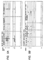
- Figs. 5A to 5E are illustration of the first embodiment showing the data in the address control table 107a. That is, the address control table 107a includes a block management table shown in Fig. 5A, a fragment management table shown in Fig. 5B, a file management table shown in Fig. 5C, a block bit map shown in Fig. 5D, and a fragment bit map 5E.
- Figs. 6A and 6B are time charts of the first embodiment showing the vertical synchronizing signals.
- the synchronizing signal generation circuit 100 generates the vertical synchronizing signals of which phases are different each other. Therefore, the video signal input circuits 101-1 and 101-2 input the video data at the different vertical synchronizing timings as shown in Figs. 6A and 6B, so that it is prevented that either of video signal of the channel 1 or the channel 2 cannot be inputted if the vertical synchronizing timings are the same or substantially the same.
- the user interface 110 further receives an endless recording command and successively recording command which are sent to the filing circuit 107 through the control circuit 109.
- the filing circuit 107 determines the first address in response to the endless recording command such that the video data recurrently is overwritten at a predetermined number of the fragments and the filling circuit 107 determines the first address such that the video data successively recorded in response to the successively recording command.
Landscapes
- Engineering & Computer Science (AREA)
- Multimedia (AREA)
- Signal Processing (AREA)
- Television Signal Processing For Recording (AREA)
- Signal Processing For Digital Recording And Reproducing (AREA)
Claims (5)
- Mehrkanal-Aufzeichnungs- und Wiedergabevorrichtung mit:einem Eingabe- und Ausgabemittel (1), das N Videokanalschaltungen (103) umfasst, zum Eingeben und Ausgeben jeweiliger Kanäle von N Videodaten, wobei N eine natürliche Zahl ist;N Datenpuffern (104) zum temporären Speichern der N Kanäle von Videodaten von den jeweiligen N Videokanalschaltungen (103);einem Speichermittel (106) zum Empfang eines Kanals der N Kanäle von Videodaten und zum Speichern der N Kanäle von Videodaten;einem Speicherschnittstellenmittel (105);einem Anwenderschnittstellenmittel (110) zum Empfang von Abrufkanaldaten, die die Verwendung von einer der N Videokanalschaltungen (103) angeben, einer Aufzeichnungsanweisung und einer Wiedergabeanweisung und einem entsprechenden Dateinamen von einem Anwender;einem Steuermittel (109) zum Betrieb der einen der N Videokanalschaltungen (103) gemäß den Abrufkanaldaten und zur Ausgabe der Aufzeichnungsanweisung, einer Wiedergabeanweisung, des entsprechenden Dateinamens und der Abrufkanaldaten von dem Anwenderschnittstellenmittel (110);einem Ablagemittel (107) mit einer Tabelle (107a) zur Bestimmung erster Adressdaten, die dem Dateinamen entsprechen, von dem Steuermittel (109) in Ansprechen auf die Aufzeichnungsanweisung von dem Steuermittel (109) und zum Speichern einer Beziehung zwischen dem Dateinamen von dem Steuermittel (109) und der ersten Adresse in der Tabelle, um eine Datei zu bilden, und zum Bestimmen von zweiten Adressdaten des Speichermittels (106) unter Verwendung des Dateinamens von dem Steuermittel (109) und der gespeicherten Beziehung in Ansprechen auf die Wiedergabeanweisungsdaten; undeinem Zugriffssteuermittel (108) zum Sammeln der Aufzeichnungsanweisung und Wiedergabeanweisung, zum Erfassen eines Betriebszustands des Speicherschnittstellenmittels (105) und zum aufeinander folgenden Liefern sowohl der gesammelten Aufzeichnungsanweisung als auch Wiedergabeanweisung, wenn das Speicherschnittstellenmittel (105) in einem Zustand ohne Betrieb ist, wobei entweder der Aufzeichnungsanweisung oder der Wiedergabeanweisung gemäß Prioritätsdaten Priorität verliehen wird, wobei das Speicherschnittstellenmittel (105) den einen der N Kanäle aus Videodaten von dem Datenpuffer in dem Speichermittel (106) in Ansprechen auf die Aufzeichnungsanweisung, die ersten Adressdaten von dem Zugriffssteuermittel (108) und die Abrufkanaldaten von dem Steuermittel (109) speichert und Videodaten von dem Speichermittel (106) in einem der N Datenpuffer (104) in Ansprechen auf die Leseanweisung von dem Zugriffssteuermittel (108) und die Abrufkanaldaten von dem Steuermittel (109) liest und speichert, um die Videodaten von dem Speichermittel (106) durch das Eingabe- und Ausgabemittel ( 1 ) auszugeben.
- Mehrkanal-Aufzeichnungs- und Wiedergabevorrichtung nach Anspruch 1, wobei das Ablagemittel (107) die Datei bildet, die Fragmente des Speichermittels (106) angibt, wobei jedes Fragment aufeinander folgende Segmente umfasst, wobei jedes Segment einen Frame der Videodaten speichert und eine Tabelle (107a) aufweist, die die erste Adresse von jedem der Fragmente und jedem der Segmente und eine Beziehung zwischen dem Dateinamen und den Fragmenten und eine Linkbeziehung der Fragmente speichert.
- Mehrkanal-Aufzeichnungs- und Wiedergabevorrichtung nach Anspruch 2, wobei die Anwenderschnittstelle (110) ferner eine Anweisung zur endlosen Aufzeichnung und eine Anweisung zur sukzessiven Aufzeichnung empfängt, und das Ablagemittel (107) die erste Adresse in Ansprechen auf die Anweisung zur endlosen Aufzeichnung bestimmt, so dass die Videodaten wiederkehrend bei einer vorbestimmten Anzahl der Fragmente überschrieben werden, und das Ablagemittel (107) die erste Adresse bestimmt, so dass die Videodaten in Ansprechen auf die Anweisung zum sukzessiven Aufzeichnen sukzessive aufgezeichnet werden.
- Mehrkanal-Aufzeichnungs- und Wiedergabevorrichtung nach einem der Ansprüche 1, 2 oder 3, ferner mit einem Mittel (100) zur Erzeugung eines Synchronisierungssignals, das eine Vielzahl vertikaler Synchronisierungssignale erzeugt und liefert, deren Phasen voneinander verschieden sind, wobei die N Videokanalschaltungen (103) jeweils auf eine Vielzahl vertikaler Synchronisierungssignale ansprechen.
- Mehrkanal-Aufzeichnungs- und Wiedergabevorrichtung nach einem der Ansprüche 1, 2 oder 3, wobei das Anwenderschnittstellenmittel eine Vielzahl von Anschlüssen (110) umfasst und das Steuermittel eine der N Videokanalschaltungen (103) einem einer Vielzahl der Anschlüsse (110) in Ansprechen auf die Abrufkanaldaten zuweist, so dass die eine der N Videokanalschaltungen (103) durch jeden einer Vielzahl der Anschlüsse (110) unabhängig gesteuert wird.
Applications Claiming Priority (6)
| Application Number | Priority Date | Filing Date | Title |
|---|---|---|---|
| JP151783/97 | 1997-06-10 | ||
| JP15178397 | 1997-06-10 | ||
| JP15178397 | 1997-06-10 | ||
| JP6278798 | 1998-03-13 | ||
| JP10062787A JPH1169279A (ja) | 1997-06-10 | 1998-03-13 | 記録再生装置 |
| JP62787/98 | 1998-03-13 |
Publications (3)
| Publication Number | Publication Date |
|---|---|
| EP0884902A2 EP0884902A2 (de) | 1998-12-16 |
| EP0884902A3 EP0884902A3 (de) | 2000-10-04 |
| EP0884902B1 true EP0884902B1 (de) | 2004-09-15 |
Family
ID=26403846
Family Applications (1)
| Application Number | Title | Priority Date | Filing Date |
|---|---|---|---|
| EP98304549A Expired - Lifetime EP0884902B1 (de) | 1997-06-10 | 1998-06-09 | Eine Vielkanal-Aufnahme und Wiedergabeanlage |
Country Status (4)
| Country | Link |
|---|---|
| US (1) | US6278837B1 (de) |
| EP (1) | EP0884902B1 (de) |
| JP (1) | JPH1169279A (de) |
| DE (1) | DE69826182T2 (de) |
Families Citing this family (28)
| Publication number | Priority date | Publication date | Assignee | Title |
|---|---|---|---|---|
| US6788882B1 (en) * | 1998-04-17 | 2004-09-07 | Timesurf, L.L.C. | Systems and methods for storing a plurality of video streams on re-writable random-access media and time-and channel- based retrieval thereof |
| US7272298B1 (en) | 1998-05-06 | 2007-09-18 | Burst.Com, Inc. | System and method for time-shifted program viewing |
| US8577205B2 (en) | 1998-07-30 | 2013-11-05 | Tivo Inc. | Digital video recording system |
| US7558472B2 (en) | 2000-08-22 | 2009-07-07 | Tivo Inc. | Multimedia signal processing system |
| US6233389B1 (en) * | 1998-07-30 | 2001-05-15 | Tivo, Inc. | Multimedia time warping system |
| US8380041B2 (en) | 1998-07-30 | 2013-02-19 | Tivo Inc. | Transportable digital video recorder system |
| AU2638900A (en) * | 1998-12-24 | 2000-07-31 | Barend Hendrik COETZER | Method of and device for video image capturing, storage and processing |
| JP2000268507A (ja) | 1999-03-19 | 2000-09-29 | Hitachi Ltd | データ記録装置 |
| GB9918772D0 (en) | 1999-08-09 | 1999-10-13 | British Sky Broadcasting Ltd | Improvements in receivers for television signals |
| JP2001067802A (ja) * | 1999-08-27 | 2001-03-16 | Toshiba Corp | マルチチャンネル記録装置及び記録方法 |
| JP2003521851A (ja) | 1999-09-20 | 2003-07-15 | ティヴォ インク | クローズド・キャプション・タグ付けシステム |
| JP4506858B2 (ja) * | 2000-01-27 | 2010-07-21 | 日本ビクター株式会社 | 情報信号記録装置、情報信号記録再生装置、情報信号記録方法、情報信号記録再生方法、情報信号再生装置 |
| WO2002037490A1 (en) * | 2000-10-30 | 2002-05-10 | Matsushita Electric Industrial Co., Ltd. | Av stream recording/reproducing device, av stream recording device, av stream recording/reproducing method, av stream recording method |
| US8272020B2 (en) | 2002-08-17 | 2012-09-18 | Disney Enterprises, Inc. | System for the delivery and dynamic presentation of large media assets over bandwidth constrained networks |
| JP2004334459A (ja) | 2003-05-07 | 2004-11-25 | Nec Corp | 記録再生装置、記録再生方法、および記録再生プログラム |
| CN1610396A (zh) * | 2003-10-20 | 2005-04-27 | 松下电器产业株式会社 | 视频录像机及视频服务器系统 |
| WO2006055920A2 (en) | 2004-11-19 | 2006-05-26 | Tivo Inc. | Method and apparatus for secure transfer of previously broadcasted content |
| US8136140B2 (en) | 2007-11-20 | 2012-03-13 | Dish Network L.L.C. | Methods and apparatus for generating metadata utilized to filter content from a video stream using text data |
| US8165451B2 (en) | 2007-11-20 | 2012-04-24 | Echostar Technologies L.L.C. | Methods and apparatus for displaying information regarding interstitials of a video stream |
| US8165450B2 (en) | 2007-11-19 | 2012-04-24 | Echostar Technologies L.L.C. | Methods and apparatus for filtering content in a video stream using text data |
| US8606085B2 (en) | 2008-03-20 | 2013-12-10 | Dish Network L.L.C. | Method and apparatus for replacement of audio data in recorded audio/video stream |
| US8156520B2 (en) | 2008-05-30 | 2012-04-10 | EchoStar Technologies, L.L.C. | Methods and apparatus for presenting substitute content in an audio/video stream using text data |
| US8407735B2 (en) | 2008-12-24 | 2013-03-26 | Echostar Technologies L.L.C. | Methods and apparatus for identifying segments of content in a presentation stream using signature data |
| US8588579B2 (en) | 2008-12-24 | 2013-11-19 | Echostar Technologies L.L.C. | Methods and apparatus for filtering and inserting content into a presentation stream using signature data |
| US8510771B2 (en) | 2008-12-24 | 2013-08-13 | Echostar Technologies L.L.C. | Methods and apparatus for filtering content from a presentation stream using signature data |
| US8437617B2 (en) | 2009-06-17 | 2013-05-07 | Echostar Technologies L.L.C. | Method and apparatus for modifying the presentation of content |
| US8934758B2 (en) | 2010-02-09 | 2015-01-13 | Echostar Global B.V. | Methods and apparatus for presenting supplemental content in association with recorded content |
| US11172269B2 (en) | 2020-03-04 | 2021-11-09 | Dish Network L.L.C. | Automated commercial content shifting in a video streaming system |
Family Cites Families (8)
| Publication number | Priority date | Publication date | Assignee | Title |
|---|---|---|---|---|
| JP2528789B2 (ja) | 1985-06-26 | 1996-08-28 | 中央電子 株式会社 | 映像情報管理装置 |
| JPH01314080A (ja) | 1988-06-13 | 1989-12-19 | Hitachi Ltd | 画像データ転送方式 |
| US5870497A (en) * | 1991-03-15 | 1999-02-09 | C-Cube Microsystems | Decoder for compressed video signals |
| US5355353A (en) | 1991-06-27 | 1994-10-11 | Binet Co., Ltd. | Data recording system of magneto-optic type |
| US5371551A (en) * | 1992-10-29 | 1994-12-06 | Logan; James | Time delayed digital video system using concurrent recording and playback |
| JPH06187302A (ja) * | 1992-12-18 | 1994-07-08 | Fujitsu Ltd | 転送要求キュー制御方式 |
| CN1064776C (zh) * | 1993-12-24 | 2001-04-18 | 索尼公司 | 信息数据记录重现装置及信息数据处理系统 |
| FR2736783B1 (fr) | 1995-07-13 | 1997-08-14 | Thomson Multimedia Sa | Procede et appareil d'enregistrement et de lecture avec un support d'enregistrement de grande capacite |
-
1998
- 1998-03-13 JP JP10062787A patent/JPH1169279A/ja active Pending
- 1998-06-08 US US09/092,972 patent/US6278837B1/en not_active Expired - Fee Related
- 1998-06-09 DE DE69826182T patent/DE69826182T2/de not_active Expired - Fee Related
- 1998-06-09 EP EP98304549A patent/EP0884902B1/de not_active Expired - Lifetime
Also Published As
| Publication number | Publication date |
|---|---|
| JPH1169279A (ja) | 1999-03-09 |
| US6278837B1 (en) | 2001-08-21 |
| DE69826182T2 (de) | 2005-10-20 |
| EP0884902A2 (de) | 1998-12-16 |
| EP0884902A3 (de) | 2000-10-04 |
| DE69826182D1 (de) | 2004-10-21 |
Similar Documents
| Publication | Publication Date | Title |
|---|---|---|
| EP0884902B1 (de) | Eine Vielkanal-Aufnahme und Wiedergabeanlage | |
| JP4294090B2 (ja) | Mpeg情報信号変換システム | |
| EP0486185B1 (de) | Vorrichtung und Verfahren zur Aufzeichnung eines Bildsignals | |
| US5291486A (en) | Data multiplexing apparatus and multiplexed data demultiplexing apparatus | |
| EP0626770A2 (de) | Datenmultiplexer und demultiplexer | |
| US5537148A (en) | Video and audio data demultiplexer having controlled synchronizing signal | |
| JP2591295B2 (ja) | フレーム位相同期方式 | |
| EP0577216A1 (de) | Verzögerungssteuerung eines Tonempfängerpuffers in einer seriellen, digitalen Videoschnittstelle | |
| US6442327B1 (en) | Video data recording and reproducing apparatus including a plurality of recording media having different capacities | |
| US6690428B1 (en) | Method and apparatus for embedding digital audio data in a serial digital video data stream | |
| US7092411B2 (en) | Transport stream multiplexing method, transport stream multiplexing apparatus, and storage and reproduction system | |
| US20020031330A1 (en) | Storage and reproduction system, transport stream storage method, and transport stream reproduction method | |
| US20030133542A1 (en) | Data recording apparatus, reproduction apparatus, recording/reproduction method, and imaging apparatus | |
| JP4200658B2 (ja) | デジタル音声及び映像データストリームの記憶方法、記憶装置及びその方法を実現する受信機 | |
| US20010007558A1 (en) | Repeat use data inserting apparatus and digital broadcast transmitting system | |
| KR100331592B1 (ko) | 정보신호송출장치 | |
| GB2228389A (en) | Apparatus for correcting time base fluctuations in digital signals | |
| US6665001B1 (en) | Multiplex and demultiplex controlling apparatus, multiplex and demultiplex controlling system, and method thereof | |
| US7116890B2 (en) | Image recording and reproducing apparatus and image recording and reproducing method | |
| JP3519996B2 (ja) | デジタル記録機器 | |
| JPH1042251A (ja) | デジタル音声データ処理装置 | |
| KR100191731B1 (ko) | 디지탈 영상 기록 재생 장치 | |
| JPH11177943A (ja) | 映像データ多重化装置 | |
| US6788879B1 (en) | Image signal processing apparatus | |
| JP3009073B2 (ja) | 多重化データ分離装置 |
Legal Events
| Date | Code | Title | Description |
|---|---|---|---|
| PUAI | Public reference made under article 153(3) epc to a published international application that has entered the european phase |
Free format text: ORIGINAL CODE: 0009012 |
|
| 17P | Request for examination filed |
Effective date: 19980617 |
|
| AK | Designated contracting states |
Kind code of ref document: A2 Designated state(s): DE FR GB |
|
| AX | Request for extension of the european patent |
Free format text: AL;LT;LV;MK;RO;SI |
|
| PUAL | Search report despatched |
Free format text: ORIGINAL CODE: 0009013 |
|
| AK | Designated contracting states |
Kind code of ref document: A3 Designated state(s): AT BE CH CY DE DK ES FI FR GB GR IE IT LI LU MC NL PT SE |
|
| AX | Request for extension of the european patent |
Free format text: AL;LT;LV;MK;RO;SI |
|
| AKX | Designation fees paid |
Free format text: DE FR GB |
|
| 17Q | First examination report despatched |
Effective date: 20021112 |
|
| GRAP | Despatch of communication of intention to grant a patent |
Free format text: ORIGINAL CODE: EPIDOSNIGR1 |
|
| GRAS | Grant fee paid |
Free format text: ORIGINAL CODE: EPIDOSNIGR3 |
|
| GRAA | (expected) grant |
Free format text: ORIGINAL CODE: 0009210 |
|
| AK | Designated contracting states |
Kind code of ref document: B1 Designated state(s): DE FR GB |
|
| REG | Reference to a national code |
Ref country code: GB Ref legal event code: FG4D |
|
| REF | Corresponds to: |
Ref document number: 69826182 Country of ref document: DE Date of ref document: 20041021 Kind code of ref document: P |
|
| ET | Fr: translation filed | ||
| PLBE | No opposition filed within time limit |
Free format text: ORIGINAL CODE: 0009261 |
|
| STAA | Information on the status of an ep patent application or granted ep patent |
Free format text: STATUS: NO OPPOSITION FILED WITHIN TIME LIMIT |
|
| 26N | No opposition filed |
Effective date: 20050616 |
|
| PGFP | Annual fee paid to national office [announced via postgrant information from national office to epo] |
Ref country code: DE Payment date: 20080612 Year of fee payment: 11 |
|
| PGFP | Annual fee paid to national office [announced via postgrant information from national office to epo] |
Ref country code: FR Payment date: 20080617 Year of fee payment: 11 |
|
| PGFP | Annual fee paid to national office [announced via postgrant information from national office to epo] |
Ref country code: GB Payment date: 20080611 Year of fee payment: 11 |
|
| GBPC | Gb: european patent ceased through non-payment of renewal fee |
Effective date: 20090609 |
|
| REG | Reference to a national code |
Ref country code: FR Ref legal event code: ST Effective date: 20100226 |
|
| PG25 | Lapsed in a contracting state [announced via postgrant information from national office to epo] |
Ref country code: FR Free format text: LAPSE BECAUSE OF NON-PAYMENT OF DUE FEES Effective date: 20090630 |
|
| PG25 | Lapsed in a contracting state [announced via postgrant information from national office to epo] |
Ref country code: GB Free format text: LAPSE BECAUSE OF NON-PAYMENT OF DUE FEES Effective date: 20090609 |
|
| PG25 | Lapsed in a contracting state [announced via postgrant information from national office to epo] |
Ref country code: DE Free format text: LAPSE BECAUSE OF NON-PAYMENT OF DUE FEES Effective date: 20100101 |