EP0884929A2 - Hochspannungsversorgung und Sicherung - Google Patents
Hochspannungsversorgung und Sicherung Download PDFInfo
- Publication number
- EP0884929A2 EP0884929A2 EP97310367A EP97310367A EP0884929A2 EP 0884929 A2 EP0884929 A2 EP 0884929A2 EP 97310367 A EP97310367 A EP 97310367A EP 97310367 A EP97310367 A EP 97310367A EP 0884929 A2 EP0884929 A2 EP 0884929A2
- Authority
- EP
- European Patent Office
- Prior art keywords
- fuse
- voltage
- lead
- power supply
- coupled
- Prior art date
- Legal status (The legal status is an assumption and is not a legal conclusion. Google has not performed a legal analysis and makes no representation as to the accuracy of the status listed.)
- Withdrawn
Links
Images

Classifications
-
- F—MECHANICAL ENGINEERING; LIGHTING; HEATING; WEAPONS; BLASTING
- F24—HEATING; RANGES; VENTILATING
- F24C—DOMESTIC STOVES OR RANGES ; DETAILS OF DOMESTIC STOVES OR RANGES, OF GENERAL APPLICATION
- F24C7/00—Stoves or ranges heated by electric energy
-
- H—ELECTRICITY
- H01—ELECTRIC ELEMENTS
- H01H—ELECTRIC SWITCHES; RELAYS; SELECTORS; EMERGENCY PROTECTIVE DEVICES
- H01H85/00—Protective devices in which the current flows through a part of fusible material and this current is interrupted by displacement of the fusible material when this current becomes excessive
- H01H85/02—Details
- H01H85/20—Bases for supporting the fuse; Separate parts thereof
- H01H85/201—Bases for supporting the fuse; Separate parts thereof for connecting a fuse in a lead and adapted to be supported by the lead alone
-
- H—ELECTRICITY
- H05—ELECTRIC TECHNIQUES NOT OTHERWISE PROVIDED FOR
- H05B—ELECTRIC HEATING; ELECTRIC LIGHT SOURCES NOT OTHERWISE PROVIDED FOR; CIRCUIT ARRANGEMENTS FOR ELECTRIC LIGHT SOURCES, IN GENERAL
- H05B6/00—Heating by electric, magnetic or electromagnetic fields
- H05B6/64—Heating using microwaves
- H05B6/66—Circuits
- H05B6/666—Safety circuits
Definitions
- the present invention relates to a high-voltage power supply circuit comprising a transformer including a high-voltage secondary winding, and a fuse.
- the present invention also relates to an assembled fuse assembly comprising an insulating body, a fuse body located within the insulating body and an insulated lead electrically connected to one terminal of the fuse body, the insulating body being configured to extend along the insulation of the lead in a direction away from the fuse body to prevent arcing from the lead.
- a known microwave oven heats food in a cooking chamber using microwave energy generated by a magnetron.
- the oven is controlled by a microprocessor.
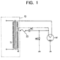
- FIG. 1 shows a known power supply unit for a microwave oven.
- the power supply unit includes a high-voltage transformer 10 generating a 2000V output, a fuse 20, a capacitor HC and a high-voltage diode HD.
- the transformer 10 comprises a primary winding T1 connected to an ac power source and a secondary winding T2.
- One end of the secondary winding T2 is connected to earth.
- the other end of the secondary winding T2 is connected to one terminal of the fuse 20.
- the other terminal of the fuse 20 is connected to one terminal of the capacitor HC.
- the other terminal of the capacitor HC is connected to the cathode of a magnetron M and to the anode of the diode HD.
- the cathode of the diode HD is connected to earth.
- the diode HD serves to provide a protective current path in the event of a voltage surge.
- the fuse 20 is provided for protection in the event of a short in any of the transformer 10, the diode HD, the capacitor HC, and the magnetron M.
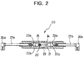
- FIG. 1 shows a fuse 20 of the type used in the power supply unit.
- the fuse 20 includes a pair of cylindrical insulating members 22a, 22b which axially engage one other, a pair of fuse holders 23a, 23b which are disposed in respective insulating members 22a, 22b, a fuse body 20' which is located between the fuse holders 23a, 23b, and a pair of lead wires 27a, 27b which are electrically connected to the outer ends of respective holders 23a, 23b, and a pair of fuse connecting ends 26a, 26b which are press-welded to ends of the lead wires 27a, 27b.
- the fuse body 20' includes a conductive fusible member 24 which is contained within an evacuated glass tube 21 and a resilient member 25 which is connected to one end of the fusible member 24.
- the resilient member 25 shrinks so that the broken surfaces of the fusible member 24 are separated by more than a predetermined distance, e.g., 15.5mm when the operational voltage of the magnetron M is 4kV. This separation is to prevent arcing between the separated parts.
- the cylindrical insulating members 22a, 22b have lengths sufficient to prevent more than the operational voltage of the magnetron M between the conductive portion of the fuse body 20' and the body of the microwave oven.
- the lengths of the cylindrical insulating members 22a, 22b are sufficient to extend behind the end of the insulation on the lead wires 27a, 27b to prevent arcing. If the magnetron M is operating at 4kV, the cylindrical insulating members 22a, 22b should extend for at least 15.5mm behind the end of the insulation on the lead wires 27a, 27b.
- a high-voltage power supply circuit is characterised in that the fuse is coupled between one end of the secondary winding and earth.
- Such a circuit preferably includes a capacitor and a surge protection diode coupled in series between the end of the secondary winding, which is not coupled to the fuse, and earth.
- the present invention is generally applicable to high-voltage power supplies of the kind identified above.
- a typical application of such a power supply is a microwave oven including a magnetron which is powered by the power supply circuit.
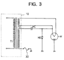
- a power supply unit includes a high-voltage transformer 10 generating a 2000V output, a fuse 10, a capacitor HC and a high-voltage diode HD.
- the transformer 10 comprises a primary winding T1 connected to an ac power source and a secondary winding T2.
- One end of the secondary winding T2 is connected to earth via the fuse 30.
- the other end of the secondary winding T2 is connected to one terminal of the capacitor HC.
- the other terminal of the capacitor HC is connected to the cathode of a magnetron M and to the anode of the diode HD.
- the cathode of the diode HD is connected to earth.
- the diode HD serves to provide a protective current path in the event of a voltage surge.
- the fuse 30 is provided for protection in the event of a short in any of the transformer 10, the diode HD, the capacitor HC, and the magnetron M.
- the potential between the fuse 30 and earth is less than 20V during the normal operation of the microwave oven. If the fuse 30 breaks, one end will be at a high-voltage and the other end at earth. Therefore, only the portion of the fuse 30 which is connected to the transformer 10 needs to be highly insulated from the earth. As a result, the length of the high-voltage fuse 30 can be smaller than is the case with prior art high-voltage fuses.
- a fuse 30 includes an insulating member 42, a first fuse holder 43 disposed in the insulating member 42, a second fuse holder 48 having an ring 48a which is opposed to the first fuse holder 43, a fuse body 40 located between the first and second fuse holders 43, 48, a lead wire 47 one end of which is electrically connected to the first fuse holder 43, and a fuse connection end 46 which is press-welded to the other end of the lead wire 47.
- the insulating member 42 is open at the earth end, and the second fuse holder 48 is fixed by the ring 48a to earth, e.g. to the chassis of a microwave oven or the body of the high-voltage transformer 10.
- the fuse body 40 includes a conductive fusible body 44 within an evacuated glass tube 41 and a resilient member 45 which is connected to one end of the fusible member 44.
- the resilient member 45 shrinks so that the broken surfaces of the fusible member 24 are separated by more than a predetermined distance, e.g., 15.5mm when the operational voltage of the magnetron M is 4kV. This separation is to prevent arcing between the separated parts.
- the insulating member 42 Since only one end of the fuse 30 need be highly insulated from earth, the insulating member 42 only need to have a length sufficient to cover the glass tube of the fuse body 40. Consequently, the fuse 30 is shorter than is known in the prior art. Experiments have shown that the length of the high-voltage fuse 30 can be reduced by 60% relative to a conventional high-voltage fuse.
- the ring 48a is fixed by a screw or or the like to earth and one of the lead wires can be omitted. Consequently, the structure of the high-voltage fuse 30 is simple and the manufacturing cost thereof is lowered.
Landscapes
- Physics & Mathematics (AREA)
- Electromagnetism (AREA)
- Engineering & Computer Science (AREA)
- Chemical & Material Sciences (AREA)
- Combustion & Propulsion (AREA)
- Mechanical Engineering (AREA)
- General Engineering & Computer Science (AREA)
- Control Of High-Frequency Heating Circuits (AREA)
- Regulation Of General Use Transformers (AREA)
- Coils Or Transformers For Communication (AREA)
- Fuses (AREA)
Applications Claiming Priority (2)
| Application Number | Priority Date | Filing Date | Title |
|---|---|---|---|
| KR1019970024715A KR100243046B1 (ko) | 1997-06-14 | 1997-06-14 | 전자렌지용 전원공급장치 및 이에 적용되는 고압퓨즈 |
| KR9724715 | 1997-06-14 |
Publications (2)
| Publication Number | Publication Date |
|---|---|
| EP0884929A2 true EP0884929A2 (de) | 1998-12-16 |
| EP0884929A3 EP0884929A3 (de) | 1999-06-09 |
Family
ID=19509570
Family Applications (1)
| Application Number | Title | Priority Date | Filing Date |
|---|---|---|---|
| EP97310367A Withdrawn EP0884929A3 (de) | 1997-06-14 | 1997-12-19 | Hochspannungsversorgung und Sicherung |
Country Status (6)
| Country | Link |
|---|---|
| US (1) | US5886327A (de) |
| EP (1) | EP0884929A3 (de) |
| JP (1) | JP2918521B2 (de) |
| KR (1) | KR100243046B1 (de) |
| CN (1) | CN1097418C (de) |
| RU (1) | RU2151472C1 (de) |
Families Citing this family (4)
| Publication number | Priority date | Publication date | Assignee | Title |
|---|---|---|---|---|
| MY120386A (en) | 1999-07-28 | 2005-10-31 | Samsung Electronics Co Ltd | High voltage transformer for microware oven and method of manufacturing therefor. |
| KR100459234B1 (ko) * | 2002-12-24 | 2004-12-03 | 엘지.필립스 엘시디 주식회사 | 백라이트 |
| CN101138062B (zh) * | 2004-09-15 | 2010-08-11 | 力特保险丝有限公司 | 高电压/高电流熔断器 |
| DE102008025917A1 (de) * | 2007-06-04 | 2009-01-08 | Littelfuse, Inc., Des Plaines | Hochspannungssicherung |
Family Cites Families (14)
| Publication number | Priority date | Publication date | Assignee | Title |
|---|---|---|---|---|
| GB1266160A (de) * | 1968-11-08 | 1972-03-08 | ||
| US3732517A (en) * | 1971-11-15 | 1973-05-08 | Westinghouse Electric Corp | Protective fuse |
| US4318150A (en) * | 1979-12-17 | 1982-03-02 | Westinghouse Electric Corp. | Protected electrical inductive apparatus |
| ZA872943B (en) * | 1986-05-22 | 1987-10-19 | Westinghouse Electric Corporation | Electrical distribution apparatus having fused draw-out surge arrester |
| GB8700530D0 (en) * | 1987-01-10 | 1987-02-11 | Y S Securities Ltd | Fuse arrangement |
| DE3741381A1 (de) * | 1987-12-07 | 1990-03-01 | Bosch Siemens Hausgeraete | Schaltungsanordnung zur mikrowellen-leistungssteuerung bei magnetrons |
| RU2054828C1 (ru) * | 1990-08-01 | 1996-02-20 | Научно-исследовательский электромеханический институт | Свч нагревательное устройство |
| RU2011319C1 (ru) * | 1990-10-22 | 1994-04-15 | Научно-исследовательский электромеханический институт | Свч нагревательное устройство |
| DE4127214C2 (de) * | 1991-08-16 | 1998-09-03 | Klaus Bruchmann | Niederspannungs-Schmelzsicherung |
| US5353216A (en) * | 1992-03-23 | 1994-10-04 | Urie & Blanton Company, Inc. | Inverter power source rack |
| RU2081518C1 (ru) * | 1993-02-16 | 1997-06-10 | Научно-исследовательский электромеханический институт | Свч-нагревательное устройство |
| US5625520A (en) * | 1993-11-19 | 1997-04-29 | Daewoo Electronics Co., Ltd. | Device for preventing a high voltage transformer of a microwave oven from being overheated |
| KR950030966U (ko) * | 1994-04-07 | 1995-11-22 | 전자렌지의 고압용 퓨즈 취부구조 | |
| JPH08251806A (ja) * | 1995-03-13 | 1996-09-27 | Matsushita Electric Ind Co Ltd | 短絡時の保護回路 |
-
1997
- 1997-06-14 KR KR1019970024715A patent/KR100243046B1/ko not_active Expired - Fee Related
- 1997-11-13 US US08/969,453 patent/US5886327A/en not_active Expired - Fee Related
- 1997-12-19 EP EP97310367A patent/EP0884929A3/de not_active Withdrawn
- 1997-12-23 CN CN97125904A patent/CN1097418C/zh not_active Expired - Fee Related
-
1998
- 1998-01-19 JP JP10008003A patent/JP2918521B2/ja not_active Expired - Lifetime
- 1998-02-13 RU RU98103263/09A patent/RU2151472C1/ru active
Also Published As
| Publication number | Publication date |
|---|---|
| KR19990001405A (ko) | 1999-01-15 |
| US5886327A (en) | 1999-03-23 |
| CN1202600A (zh) | 1998-12-23 |
| EP0884929A3 (de) | 1999-06-09 |
| KR100243046B1 (ko) | 2000-03-02 |
| JPH1116674A (ja) | 1999-01-22 |
| RU2151472C1 (ru) | 2000-06-20 |
| CN1097418C (zh) | 2002-12-25 |
| JP2918521B2 (ja) | 1999-07-12 |
Similar Documents
| Publication | Publication Date | Title |
|---|---|---|
| CA2000467C (en) | High-frequency heating apparatus using frequency-converter-type power supply | |
| US4353012A (en) | Pulse injection starting for high intensity discharge metal halide lamps | |
| WO1991018375A1 (en) | Voltage pick-up circuit and flashing display for high voltage indicator device and input electrode therefor | |
| DE3166324D1 (en) | Current transformer with annular case to be built in a metal cast high-tension switchgear installation | |
| EP0884929A2 (de) | Hochspannungsversorgung und Sicherung | |
| US6191538B1 (en) | High-pressure discharge lamp having a base at one end and a starting device integrated in the base | |
| US3309477A (en) | Protective means for encased electrical apparatus | |
| CA1086817A (en) | Compressed gas filled circuit breaker | |
| MXPA98004763A (en) | Unit of supply of energy for a microwave oven and a fuse of high voltage used in the mi | |
| CA1141428A (en) | Protected electrical inductive apparatus | |
| KR200143526Y1 (ko) | 전자렌지의 고전압트랜스보호용 휴즈장착구조 | |
| EP1396059B1 (de) | Schutzeinrichtung, welche bei spannungsüberschlag aktiviert wird | |
| JP2514607Y2 (ja) | 配電盤 | |
| KR200143524Y1 (ko) | 전자 렌지의 고압 트랜스 보호용 퓨즈 장착 구조 | |
| KR200146188Y1 (ko) | 전자 렌지의 고압 트랜스 보호용 퓨즈 장착 구조 | |
| KR200146187Y1 (ko) | 전자 렌지의 고압 트랜스 보호용 퓨즈 장착 구조 | |
| JPH054695Y2 (de) | ||
| JP2516413B2 (ja) | 高周波加熱器の電源装置 | |
| WO1992010921A1 (en) | High voltage protection resistor | |
| KR0139296Y1 (ko) | 전자 렌지의 고압 트랜스 보호용 퓨즈 장착 구조 | |
| KR200143527Y1 (ko) | 전자렌지의 고전압트랜스보호용 휴즈장착구조 | |
| JPH03104105A (ja) | フライバックトランス | |
| JPH088181B2 (ja) | 補償リアクトル装置 | |
| JPH02103887A (ja) | 高周波加熱装置 | |
| JPS61188883A (ja) | 高周波加熱装置 |
Legal Events
| Date | Code | Title | Description |
|---|---|---|---|
| PUAI | Public reference made under article 153(3) epc to a published international application that has entered the european phase |
Free format text: ORIGINAL CODE: 0009012 |
|
| AK | Designated contracting states |
Kind code of ref document: A2 Designated state(s): DE FR GB |
|
| AX | Request for extension of the european patent |
Free format text: AL;LT;LV;MK;RO;SI |
|
| PUAL | Search report despatched |
Free format text: ORIGINAL CODE: 0009013 |
|
| AK | Designated contracting states |
Kind code of ref document: A3 Designated state(s): AT BE CH DE DK ES FI FR GB GR IE IT LI LU MC NL PT SE |
|
| AX | Request for extension of the european patent |
Free format text: AL;LT;LV;MK;RO;SI |
|
| 17P | Request for examination filed |
Effective date: 19991208 |
|
| AKX | Designation fees paid |
Free format text: AT BE CH LI |
|
| RBV | Designated contracting states (corrected) |
Designated state(s): DE FR GB |
|
| REG | Reference to a national code |
Ref country code: DE Ref legal event code: 8566 |
|
| 17Q | First examination report despatched |
Effective date: 20010123 |
|
| RTI1 | Title (correction) |
Free format text: MICROWAVE OVEN WITH HIGH-VOLTAGE POWER SUPPLY AND FUSE |
|
| RTI1 | Title (correction) |
Free format text: MICROWAVE OVEN WITH HIGH-VOLTAGE POWER SUPPLY AND FUSE |
|
| RTI1 | Title (correction) |
Free format text: MICROWAVE OVEN WITH HIGH-VOLTAGE POWER SUPPLY AND FUSE |
|
| GRAH | Despatch of communication of intention to grant a patent |
Free format text: ORIGINAL CODE: EPIDOS IGRA |
|
| STAA | Information on the status of an ep patent application or granted ep patent |
Free format text: STATUS: THE APPLICATION IS DEEMED TO BE WITHDRAWN |
|
| 18D | Application deemed to be withdrawn |
Effective date: 20030116 |