EP0885133B1 - Radialer reifen mit einer karkasse, deren überlappungsspleissen mit einschnitten versehen ist - Google Patents
Radialer reifen mit einer karkasse, deren überlappungsspleissen mit einschnitten versehen ist Download PDFInfo
- Publication number
- EP0885133B1 EP0885133B1 EP97905117A EP97905117A EP0885133B1 EP 0885133 B1 EP0885133 B1 EP 0885133B1 EP 97905117 A EP97905117 A EP 97905117A EP 97905117 A EP97905117 A EP 97905117A EP 0885133 B1 EP0885133 B1 EP 0885133B1
- Authority
- EP
- European Patent Office
- Prior art keywords
- radial
- tyre
- edges
- weld
- cut
- Prior art date
- Legal status (The legal status is an assumption and is not a legal conclusion. Google has not performed a legal analysis and makes no representation as to the accuracy of the status listed.)
- Expired - Lifetime
Links
- 230000002787 reinforcement Effects 0.000 claims description 48
- 239000004744 fabric Substances 0.000 claims description 32
- 229920000139 polyethylene terephthalate Polymers 0.000 claims description 11
- 239000005020 polyethylene terephthalate Substances 0.000 claims description 11
- 229920000728 polyester Polymers 0.000 claims description 7
- -1 polyethylene terephthalate Polymers 0.000 claims description 2
- 238000004519 manufacturing process Methods 0.000 description 17
- 238000003466 welding Methods 0.000 description 15
- 238000005520 cutting process Methods 0.000 description 13
- 239000011324 bead Substances 0.000 description 10
- 238000000034 method Methods 0.000 description 7
- 229910000679 solder Inorganic materials 0.000 description 7
- 210000001519 tissue Anatomy 0.000 description 7
- 235000009508 confectionery Nutrition 0.000 description 5
- 230000007547 defect Effects 0.000 description 5
- 239000000463 material Substances 0.000 description 4
- 238000002360 preparation method Methods 0.000 description 4
- 230000003014 reinforcing effect Effects 0.000 description 4
- 239000004753 textile Substances 0.000 description 4
- 238000010276 construction Methods 0.000 description 3
- 230000008602 contraction Effects 0.000 description 3
- 230000006378 damage Effects 0.000 description 3
- 239000000835 fiber Substances 0.000 description 3
- 230000004048 modification Effects 0.000 description 3
- 238000012986 modification Methods 0.000 description 3
- 241001080024 Telles Species 0.000 description 2
- 125000003118 aryl group Chemical group 0.000 description 2
- 230000008901 benefit Effects 0.000 description 2
- 230000006872 improvement Effects 0.000 description 2
- 238000007373 indentation Methods 0.000 description 2
- 239000012528 membrane Substances 0.000 description 2
- 230000003287 optical effect Effects 0.000 description 2
- 238000007493 shaping process Methods 0.000 description 2
- 229920000742 Cotton Polymers 0.000 description 1
- 229920000914 Metallic fiber Polymers 0.000 description 1
- 239000004952 Polyamide Substances 0.000 description 1
- UREZNYTWGJKWBI-UHFFFAOYSA-M benzethonium chloride Chemical compound [Cl-].C1=CC(C(C)(C)CC(C)(C)C)=CC=C1OCCOCC[N+](C)(C)CC1=CC=CC=C1 UREZNYTWGJKWBI-UHFFFAOYSA-M 0.000 description 1
- 230000015572 biosynthetic process Effects 0.000 description 1
- 238000003490 calendering Methods 0.000 description 1
- 230000015556 catabolic process Effects 0.000 description 1
- 229920002678 cellulose Polymers 0.000 description 1
- 239000001913 cellulose Substances 0.000 description 1
- 238000010411 cooking Methods 0.000 description 1
- 238000006731 degradation reaction Methods 0.000 description 1
- 230000001627 detrimental effect Effects 0.000 description 1
- 230000000694 effects Effects 0.000 description 1
- 238000005304 joining Methods 0.000 description 1
- 239000011159 matrix material Substances 0.000 description 1
- 239000002184 metal Substances 0.000 description 1
- 229920002647 polyamide Polymers 0.000 description 1
- 238000011084 recovery Methods 0.000 description 1
- 230000009467 reduction Effects 0.000 description 1
- 238000005096 rolling process Methods 0.000 description 1
- 238000007789 sealing Methods 0.000 description 1
- 239000011265 semifinished product Substances 0.000 description 1
- 238000005476 soldering Methods 0.000 description 1
- 238000011144 upstream manufacturing Methods 0.000 description 1
- 239000002759 woven fabric Substances 0.000 description 1
Images

Classifications
-
- B—PERFORMING OPERATIONS; TRANSPORTING
- B60—VEHICLES IN GENERAL
- B60C—VEHICLE TYRES; TYRE INFLATION; TYRE CHANGING; CONNECTING VALVES TO INFLATABLE ELASTIC BODIES IN GENERAL; DEVICES OR ARRANGEMENTS RELATED TO TYRES
- B60C9/00—Reinforcements or ply arrangement of pneumatic tyres
- B60C9/02—Carcasses
- B60C9/04—Carcasses the reinforcing cords of each carcass ply arranged in a substantially parallel relationship
- B60C9/08—Carcasses the reinforcing cords of each carcass ply arranged in a substantially parallel relationship the cords extend transversely from bead to bead, i.e. radial ply
-
- Y—GENERAL TAGGING OF NEW TECHNOLOGICAL DEVELOPMENTS; GENERAL TAGGING OF CROSS-SECTIONAL TECHNOLOGIES SPANNING OVER SEVERAL SECTIONS OF THE IPC; TECHNICAL SUBJECTS COVERED BY FORMER USPC CROSS-REFERENCE ART COLLECTIONS [XRACs] AND DIGESTS
- Y10—TECHNICAL SUBJECTS COVERED BY FORMER USPC
- Y10T—TECHNICAL SUBJECTS COVERED BY FORMER US CLASSIFICATION
- Y10T152/00—Resilient tires and wheels
- Y10T152/10—Tires, resilient
- Y10T152/10495—Pneumatic tire or inner tube
- Y10T152/10855—Characterized by the carcass, carcass material, or physical arrangement of the carcass materials
Definitions
- the present invention relates to radial tires and to reinforcements intended to strengthen the carcass of such tires.
- carcass reinforcements consist of at least one ply, hereinafter referred to as radial ply or radial carcass ply, prepared in the form of a semi-finished product which essentially consists of an elastomeric matrix reinforced with wires.
- radial wires are arranged at regular intervals, and parallel to each other, in one direction substantially radial, i.e. a direction making an angle of about 90 ⁇ 10 ° with the tangent to the circumferential direction of the tire.
- Each radial ply is normally in the form of an annular element continuous which is formed, when making the carcass reinforcement on a drum, by cutting strips or strips of rubberized fabric, then assembling the two edges of fabric thus cut on the drum, by means of a joint, also called solder, allowing to connect these two edges.
- tissue strips are normally cut between two radial wires, and parallel to them to avoid them cut.
- the present invention specifically relates to an improvement made to welds by covering the radial plies constituting the carcass reinforcements of the radial tires.
- the overlap welding technique consists of cover one edge of the fabric cut by its other edge, at a certain distance, and to ensure the connection by application of pressure. After cooking the envelope, this type of weld has great strength, due to the large adhesion surface which can be exercised between the covering parts.
- These cuts generally consist of narrow incisions (without removal of material) or in large notches (with removal of material - technique known as "notching") practiced on the confection, and are generally located at any point on the side of the pneumatic up to the internal part of the bead (bead zone located at inside the envelope), or even under the rod (see for example the US-A-4,466,473 or EP-B-0,117,137, and patent applications published under Nos JP1986 / 83025, JP1986 / 94745, JP1986 / 218402).
- US-A-4,466,473 or equivalent patent EP-B-0 117,137 describe a method of manufacturing a radial carcass reinforcement which consists in practice, in only one of the two overlapping edges, all along this edge and at regular intervals, a plurality of cuts perpendicular to the direction of the radial wires, of depth substantially equal to the overlap width, this edge then being covered by the other edge to form the overlap weld.
- An object of the present invention is to provide a significantly improved tire in concerning the appearance and uniformity of its sides, this without prejudice to its other performances.
- Another object of the invention is to offer such a tire without difficulties or additional cost of manufacturing, the latter can be made on automatic machines operating at high speed, without requiring manual intervention, and therefore without decrease productivity.
- the radial tire of the invention having at least one crown reinforcement and one carcass reinforcement consisting of at least one sheet of rubberized fabric comprising radial wires, substantially parallel to the radial direction, said radial ply comprising at least one overlap weld formed by the overlapping of two edges of said fabric and circumferentially limited by two selvedges, is characterized in that said weld comprises, in each of these two edges, at least one cut located under the crown reinforcement, cutting a plurality of radial wires.
- the tire of the invention has a carcass reinforcement formed by at least one continuous annular element (radial ply) welded by the overlapping of two ends of rubberized fabric, and welding by overlapping thus obtained, of small dimension in the circumferential direction, is notched, with the radial wires it contains, by at least one transverse cut in each overlap edge of the weld, this cut being located under the top tire.
- the above cut has a depth greater than half the width of overlap welding, these two dimensions being measured in the direction circumferentially.
- the cut is a so-called “whole” cut, the depth of which is greater than the total width of the weld, said weld being thus traversed entirely, from one edge to the other, by this entire cut.
- the invention relates more particularly to a tire whose carcass reinforcement has a single radial ply.
- FIG. 1 shows, schematically and very generally, a radial section a tire casing with a radial carcass reinforcement, this casing which may or may not conform to the invention, in this representation General.
- This envelope 10 has two sides 11 joined by a strip of bearing 12, a crown reinforcement 13 extending from one edge 13a to the other edge 13b, a carcass reinforcement 14 anchored to two rods 15 in each bead 16 up to the two lateral ends 14a and 14b of this frame 14.
- the carcass reinforcement 14 consists of at least one radial ply containing radial reinforcing wires which are arranged practically parallel to each other others and which extend from one bead to the other in a substantially radial direction, so as to form an angle between 80 ° and 90 ° with the circumferential plane median M-M.
- median circumferential plane is understood in known manner the plane perpendicular to the axis of rotation of the tire which is located midway between the two beads 15 and which therefore passes through the middle of the crown reinforcement 13.
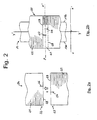
- FIG. 2 represents, seen from below, for a tire casing 10 according to the invention, a portion of radial carcass ply 20 comprising a overlap weld 21 (fig. 2b), as well as the two edges or ends 22 and 23 of the same strip of rubberized fabric 24 (fig. 2a), these two edges being intended to be superimposed, overlapping, to form the weld 21.
- the ply portion 20 constitutes a part of the carcass reinforcement 14, the central part of which is located under the crown reinforcement 13 of the tire 10 according to the invention, said reinforcement 13 being delimited laterally, in FIG. 2b, by its two ends 13a and 13b.
- this portion of sheet 20 and its overlap weld 21 are shown schematically, projected flat, before conformation of the envelope, and not in the toroidal form which is adopted once the envelope is conformed.
- This radial ply 20 is reinforced with continuously by radial wires 25, arranged at regular intervals and substantially parallel to each other. For clarity of the figures, it goes without saying that these wires 25 were only partially represented.
- these radial threads are plied in polyester, in particular in polyethylene terephthalate (PET).
- PET polyethylene terephthalate
- the direction of these radial wires 25 is substantially radial, ie substantially parallel to the direction of the strictly radial axis (xx '), i.e. their direction makes a angle of 0 ⁇ 10 ° with the axis (xx ') which is itself perpendicular to the axis circumferential (yy ') (axis tangent to the circumferential direction).
- the axis (yy ') represented here is the median circumferential axis, contained in the median circumferential plane M-M shown in Figure 1, passing through the middle of the crown reinforcement 13 of the tire 10, ie halfway between the two ends 13a and 13b of said frame.
- the ply 20 When making the tire of the invention on a drum, before the step of conformation of the envelope, the ply 20 normally consists of an element continuous annular in a direction perpendicular to the axis of the radial wires, i.e. substantially parallel to the direction (yy '), this continuous element being formed by covering and joining the two edges (22, 23) of the same strip of fabric 24. practice in each edge (22, 23) a cut (26, 27) and only one, of depth given, extending from each respective selvedge (28, 29) towards the interior of the fabric, in a direction substantially perpendicular to the axis of the radial wires 25, this cut-out severing a plurality of these radial wires.
- each cut is oriented in a substantially circumferential direction, that is to say a direction making an angle of 0 ⁇ 10 ° with the strictly circumferential direction (Yy ').
- Yy ' the strictly circumferential direction
- the invention can be implemented with greater angles, for example example from 20 to 30 °, or even more.
- the cuts consist of simple incisions, that is to say in fine cuts without removing tissue, but the invention also applies to cases where we use wider cutouts with removal of fabric (technique called "notching"), such as notches or indentations of different shapes.
- the density of radial threads is doubled compared to the rest of the welded ply.
- the density of the radial wires, outside the weld is generally known between a few tens and a few hundred of threads per dm (decimetre), for example between 50 and 250 threads / dm, which corresponds to a interval between two radial wires (distance from axis to axis) between a few tenths of mm (millimeter) and a few mm, for example between 0.4 and 2.0 mm.
- the density of radial wires in the case illustrated in FIG. 2, is approximately 100 threads / dm of ply outside the weld, and therefore around 200 threads / dm of ply inside the weld.
- the dimension of the weld in the circumferential direction (yy '), that is to say the distance separating the two selvedges, is called the weld width
- the length of each cut, in this same circumferential direction (yy ') is called cutting depth.
- cutting depth is meant, not the length of the cut itself, but the length of its projection on the circumferential axis (yy ').
- the two cutouts 26 and 27 preferably have a depth greater than half the width solder, as shown clearly in Figure 2b, since each cutout, starting from each respective selvedge towards the inside of the weld, extends to beyond the median axis (zz ') of the weld.
- the width of the overlap weld can vary from a few millimeters to a few tens of millimeters depending on the particular characteristics of the pneumatic manufactured.
- this width is preferably between 2 and 10 mm.
- these two cutouts are offset from each other, i.e. not superimposed, for example they are positioned substantially symmetrically on either side of the median circumferential plane, as illustrated for example in Figure 2b.
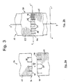
- the overlap welding of the radial ply may include, under the crown reinforcement, a plurality of cutouts in each of the two overlapping edges, as illustrated for example on the figure 3.
- FIG. 3 shows schematically another example of a tire 10 according to the invention. It represents, seen from below and projected flat, a portion of radial carcass ply 30 having an overlap weld 31 (fig. 3b), as well as the two edges 32 and 33 of the same strip of rubberized fabric 34 (fig. 3a), these two edges being intended to be superimposed to form the weld 31.
- each weld edge (32, 33) there is practiced in each weld edge (32, 33) a plurality of cutouts (36, 37), of given depth, extending from each respective selvedge (38, 39) towards the inside of the weld in a substantially circumferential direction, and severing a plurality of radial wires 25. The whole is shown in FIG.
- the cuts 36 and the cuts 37 are here whole cuts, the depth of which is greater than the weld width; each of them crosses the entire weld 31, from a given edge to beyond the opposite edge.
- the overlap weld of the radial ply comprises, under the crown reinforcement, a plurality of cutouts in each of the two overlapping edges
- these cutouts are preferably distributed in substantially equal number on the two overlapping edges and uniformly, while being offset from each other, from one edge to the other, so as to that there are no opposite cuts (i.e. located on two edges or selvedges opposite) that are superimposed.
- each radial wire 25 normally forms a continuous reinforcing arch extending, according to a meridian, over the entire width of the tire, wound in each bead 16, under each of the two rods 15, to the two lateral ends 14a and 14b of the carcass reinforcement 14 (fig. 1).
- the continuity of the reinforcement arches is then interrupted over the entire width of the weld, and even beyond, in each of the two overlapping edges.
- the indicated values of the cut depths, weld widths, minimum distances between two cuts, or wire densities are the values measured in a plane, when the radial ply and its overlap weld are shown laid at dish.
- the average distance between two cuts, measured along the main axis (zz ') of the solder, is preferably greater than 10 mm, more preferably greater than 15 mm, whether these two cuts are opposite or adjacent (i.e. located on two opposite edges, or on the same edge, respectively).
- the cutouts start from the edge to propagate towards the inside of the weld, as illustrated previously on the Figures 2 and 3. But the invention also applies to cases where cutouts are internal to the weld, that is to say do not extend to one and / or the other of the two edges, remaining located within the overlap area.
- the different cuts made in each of the two overlapping edges of the solder can have the same length, or different lengths.
- these cutouts are identical for each of the two edges. So the operation of cutting on the fabric strips, when making the tire, is the same for each weld edge or edge, and can therefore be secured by the same tool, at a high rate.
- the welds do not contain overlapping cutouts. This is particularly the case when using, for the manufacturing the tire, a construction drum devoid of membrane: the inner ply (sealing rubber) then acting as a membrane, this ply may slip through two overlapping cutouts that are too wide open during the step of shaping the envelope, and thus passing through the sheet radial which directly covers this inner ply.
- the number and the depth cuts under the tire crown reinforcement can vary within a to a large extent, depending in particular on the importance of the defect to be corrected, the particular structure of the tire manufactured and the manufacturing means used.
- the overlap welding of the radial ply does not has cutouts, in each of its two edges, only under the crown reinforcement tire.
- each series containing 70 envelopes different.
- the tires of each series have two sides 11 joined by a tread 12, a frame of crown 13 extending from one edge 13a to the other edge 13b, a carcass reinforcement 14 anchored to two rods 15 in each bead 16 to the two lateral ends 14a and 14b of this frame 14.
- the crown reinforcement 13 comprises, conventionally, two superposed plies, reinforced by substantially parallel and inclined metal cables of approximately 22 degrees from the median circumferential plane, these layers being crossed by compared to this same plan.
- the carcass reinforcement 14 consists of a single radial ply reinforced with threads radial in PET (standard PET called “regular"). These radial threads are plied from formula 110x3 (tex) 275Z / 275S, that is to say that each of these plies consists of three yarns (multifilament fibers), whose title is equal to 110 tex before twisting, which are twisted individually at 275 turns per meter in the Z direction during a first step, then twisted the three together in reverse (direction S) at 275 turns per meter in a second step.
- the density of radial wires, outside the solder, is 111 wires per dm of radial ply, the distance between two radial wires adjacent, from axis to axis, therefore being approximately 0.9 millimeter.
- This radial sheet includes an overlap weld whose axis (zz ') is substantially parallel to that of the radial wires. This weld is about 6mm wide, so it contains 6 with 7 radial wires in each overlap edge, and its total length, along the axis (zz '), from one end 14a to the other end 14b of the radial ply 14, is approximately 550 mm.
- Each envelope is mounted on a rim and inflated to 3.5 bar, then the hollow deformation due to overlap welding, by measuring the depth average of said trough by means of a known optical device, comprising essentially a laser beam, an optical sensor and recording means.
- the deformation is recorded at a large number of points (several hundred), on each side of the envelope, then we calculate the average depth for each envelope tested.
- the average value of the depression is 0.238 mm, while it is 0.555 mm, i.e. much more than double, for all B series tires.
- the C series envelopes are checked in the same way as above. We then notes that all the envelopes tested respond positively to the test, i.e. that they all have a deformation whose average depth is less than 0.500 mm. For all tires in the C series, the average value of the depression is 0.240 mm, with average depths per envelope varying from 0.100 to 0.430 mm.
- the two cuts have been practiced on both sides and at equal distance (about 28 mm) from the plane median circumference M-M, this distance being measured along the median axis (zz ') of the welding.
- the single cutout on the edge radially outside of the overlap weld was substantially centered under the crown reinforcement, in the median circumferential plane M-M.
- overlap welding does not include no cutout other than that (s) located under the top reinforcement of the envelopes.
- control envelopes of the D series (radial ply reinforced with PET "HMLS") exhibited a slight intaglio deformation of their flank, the calculated average depth being less than 0.350 mm.
- the hollow deformations are significantly less pronounced in the sidewalls of radial tires, and the traces of welds by much less visible overlap.
- the cuts according to the invention on each of the two edges of the weld by overlap, have a different function. These cutouts, opening more or less during the manufacture of the envelope, essentially in the direction of the radial wires, will allow the weld to deform more than the surrounding tissue, and thus make it possible to rebalance the lengths of the meridians occupied by the radial wires, between the inside of the overlap weld and the rest of the sheet, to the side of the inflated tire.
- the invention can also be applied to cases where the radial wires are not used alone to reinforce the radial plies, but associated with other wires not radial.
- the radial ply may consist of a woven fabric comprising, known manner, warp threads and weft threads, the warp threads being the threads radials 25 shown in FIGS. 2 and 3, crossed with non-weft threads shown in these figures, for example weft son in polyester and / or cotton.
- each of these welds by covering includes, in each of its two edges, at least one cutout located under the crown reinforcement of the tire, severing a plurality of wires radial, such a cut being more preferably an entire cut whose depth is greater than the width of the overlap weld.
- the characteristics of the radial wires, their nature, their arrangement are the same inside as outside the weld, which makes it possible to manufacture the tire of the invention starting from standard, homogeneous fabrics.
- the manufacture of the tires of the invention requires no intervention particular manual to control or adjust the depths of cuts, the number cut radial wires, or the widths of overlap welds. She does not also does not require the use of more precise machines than manufacturing usually used for manufacturing radial tires classics.
- the tires of the invention can in particular be produced on automatic machines operating at high speed, without loss of productivity.
- Radial wires could be other wires textiles, such as textile yarns based on polyamide, aromatic or not aromatic, cellulose-based fibers, or other non-textile yarn, for example metallic, or hybrid wires made with different materials.
- each of the radial wires may consist for example of a single unitary wire, of shape cylindrical or not, or, of an assembly of several unitary wires, forming by example a cable, a twisted, a multifilament fiber twisted on itself, each unitary yarn which may in particular consist of either a single filament, for example a monofilament of large diameter, or of several filaments.
- This definition is valid whatever the cross section of the unitary wire, the material, the technique assembly when it comes to assembled wires.
Landscapes
- Engineering & Computer Science (AREA)
- Mechanical Engineering (AREA)
- Tires In General (AREA)
- Tyre Moulding (AREA)
Claims (14)
- Radialreifen(10), der mindestens eine Scheitelbewehrung (13) und eine Karkassenbewehrung (14) aufweist, die aus mindestens einer Lage (20, 30) aus gummiertem Tuch (24, 34) gebildet ist, das Radialdrähte (25) aufweist, wobei die genannte Radiallage (20, 30) mindestens eine Überdeckungsschweißung (21, 31) aufweist, die durch Überlagerung der beiden Ränder (22, 23; 32,33) des genannten Tuches gebildet und in Umfangsrichtung durch zwei Kanten (28, 29; 38, 39) begrenzt ist, dadurch gekennzeichnet, daß die genannte Schweissung (21, 31) in jedem ihrer genannten Ränder mindestens einen Einschnitt (26, 27; 36, 37) aufweist, der unter der Scheitelbewehrung (13) angeordnet ist und eine Mehrzahl von Radialdrähten (25) durchschneidet.
- Reifen (10) nach Anspruch 1, dadurch gekennzeichnet, daß der genannte Einschnitt (26, 27; 36, 37) eine Tiefe aufweist, die größer ist als die halbe Breite der Überdeckungsschweißung (21, 31), wobei diese beiden Abmessungen in Umfangsrichtung (yy') gemessen sind.
- Reifen (10) nach Anspruch 2, dadurch gekennzeichnet, daß der genannte Einschnitt (36, 37) eine Tiefe aufweist, die größer ist als die Breite der Überdeckungsschweißung (31).
- Reifen (10) nach irgendeinem der Ansprüche 1 bis 3, dadurch gekennzeichnet, daß in jedem Rand (22, 23; 32, 33) der Überdeckungsschweißung (21, 31) der genannte Einschnitt (26, 26; 36, 37) sich von der Kante (28, 29; 38, 39) aus zur Innenseite der Schweißung (21, 31) hin erstreckt.
- Reifen (10) nach irgendeinem der Ansprüche 1 bis 4, dadurch gekennzeichnet, daß er ein Reifen für einen PKW oder einen Kleinlastwagen ist, und daß der genannte Einschnitt (26, 27; 36, 37) eine Tiefe von mehr als 3 mm aufweist.
- Reifen (10) nach irgendeinem der Ansprüche 1 bis 5, dadurch gekennzeichnet, daß die Überdeckungsschweißung (31) eine Mehrzahl bzw. Vielzahl von Einschnitten (36, 37) unter der Scheitelbewehrung (13) in jeden seiner beiden Ränder (32, 33) aufweist, die in im wesentlichen gleicher Zahl über diese beiden Ränder verteilt sind.
- Reifen (10) nach irgendeinem der Ansprüche 1 bis 6, dadurch gekennzeichnet, daß die Überdeckungsschweißung (21, 31) keine übereinanderliegenden Einschnitte (26, 27; 36, 37) aufweist.
- Reifen (10) nach Anspruch 7, dadurch gekennzeichnet, daß der mittlere Abstand zwischen zwei Einschnitten (26, 27; 36, 37), längs der Achse (zz') der Schweißung (21, 31) gemessen, größer ist als 10 Millimeter.
- Reifen (10) nach irgendeinem der Ansprüche 1 bis 8, deren Radiallage (20, 30) mehrere Überdeckungsschweißungen (21, 31) enthält, dadurch gekennzeichnet, daß jede Überdeckungsschweißung in jedem ihrer beiden Ränder (22, 23; 32, 33) mindestens einen Einschnitt (26, 27; 36, 37) aufweist, der unter der Scheitelbewehrung (13) angeordnet ist und eine Vielzahl von Radialdrähten (25) schneidet.
- Reifen (10) nach Anspruch 9, dadurch gekennzeichnet, daß der genannte Einschnitt (36, 37) eine Tiefe aufweist, die größer ist als die Breite der Überdeckungsschweißung (31).
- Reifen (10) nach irgendeinem der Ansprüche 1 bis 10, dadurch gekennzeichnet, daß die Überdeckungsschweißung (21, 31) nur Einschnitte (26, 27; 36, 37) in jedem ihrer Ränder (22, 23; 32, 33) unter der Scheitelbewehrung (13) aufweist.
- Reifen (10) nach irgendeinem der Ansprüche 1 bis 11, dadurch gekennzeichnet, daß die Scheitelbewehrung (14) eine einzige Radiallage (20; 30) aufweist.
- Reifen (10) nach irgendeinem der Ansprüche 1 bis 12, dadurch gekennzeichnet, daß die Radialdrähte (25) auf Polyesterbasis beruhen.
- Reifen (10) nach Anspruch 13, dadurch gekennzeichnet, daß der Polyester Polyethylenterephthalat ist.
Applications Claiming Priority (3)
| Application Number | Priority Date | Filing Date | Title |
|---|---|---|---|
| FR9602866 | 1996-03-05 | ||
| FR9602866A FR2745754B1 (fr) | 1996-03-05 | 1996-03-05 | Pneu radial comportant une nappe carcasse dont la soudure par recouvrement est pourvue de decoupes |
| PCT/EP1997/000971 WO1997032740A1 (fr) | 1996-03-05 | 1997-02-28 | Pneu radial comportant une nappe carcasse dont la soudure par recouvrement est pourvue de decoupes |
Publications (2)
| Publication Number | Publication Date |
|---|---|
| EP0885133A1 EP0885133A1 (de) | 1998-12-23 |
| EP0885133B1 true EP0885133B1 (de) | 2002-09-11 |
Family
ID=9489947
Family Applications (1)
| Application Number | Title | Priority Date | Filing Date |
|---|---|---|---|
| EP97905117A Expired - Lifetime EP0885133B1 (de) | 1996-03-05 | 1997-02-28 | Radialer reifen mit einer karkasse, deren überlappungsspleissen mit einschnitten versehen ist |
Country Status (12)
| Country | Link |
|---|---|
| US (1) | US6129129A (de) |
| EP (1) | EP0885133B1 (de) |
| JP (1) | JP2000512586A (de) |
| KR (1) | KR100558587B1 (de) |
| CN (1) | CN1072568C (de) |
| AU (1) | AU1878597A (de) |
| BR (1) | BR9707919A (de) |
| CA (1) | CA2248193C (de) |
| DE (1) | DE69715387T2 (de) |
| ES (1) | ES2183135T3 (de) |
| FR (1) | FR2745754B1 (de) |
| WO (1) | WO1997032740A1 (de) |
Families Citing this family (8)
| Publication number | Priority date | Publication date | Assignee | Title |
|---|---|---|---|---|
| US7820565B2 (en) * | 2001-05-03 | 2010-10-26 | Barrday Inc. | Densely woven quasi-unidirectional fabric for ballistic applications |
| MXPA03010061A (es) * | 2001-05-03 | 2005-04-28 | Barrday Inc | Tela cuasi-unidireccional para usos balisticos. |
| FR2885079B1 (fr) * | 2005-05-02 | 2007-07-06 | Michelin Soc Tech | Pneumatique et procede de fabrication |
| FR2977828B1 (fr) * | 2011-07-13 | 2013-08-16 | Michelin Soc Tech | Pneumatique pliable, procede de pliage et utilisation |
| US10160264B2 (en) * | 2012-10-03 | 2018-12-25 | The Yokohama Rubber Co., Ltd. | Pneumatic tire |
| CN105960337A (zh) * | 2014-02-06 | 2016-09-21 | 普利司通美国轮胎运营有限责任公司 | 具有不连续胎体帘布层构造的轮胎结构 |
| JP6351481B2 (ja) * | 2014-10-29 | 2018-07-04 | 住友ゴム工業株式会社 | 空気入りタイヤの製造方法 |
| US10960628B2 (en) | 2015-09-15 | 2021-03-30 | The Goodyear Tire & Rubber Company | Tire carcass ply joining apparatus and method |
Family Cites Families (5)
| Publication number | Priority date | Publication date | Assignee | Title |
|---|---|---|---|---|
| US4466473A (en) * | 1983-02-22 | 1984-08-21 | The General Tire & Rubber Company | Tire ply splice construction and method of making the same |
| CA1231296A (en) * | 1983-03-17 | 1988-01-12 | David Reifsnyder | Tire ply splice construction and method of making the same |
| JPS6183025A (ja) * | 1984-09-28 | 1986-04-26 | Toyo Tire & Rubber Co Ltd | ラジアルタイヤの製造法 |
| US5658405A (en) * | 1994-10-21 | 1997-08-19 | Sumitomo Rubber Industries, Ltd. | Pneumatic radial tire with carcass overlap joint having at least one circumferential cut |
| JPH08118909A (ja) * | 1994-10-21 | 1996-05-14 | Sumitomo Rubber Ind Ltd | 空気入りラジアルタイヤ及びその製造方法 |
-
1996
- 1996-03-05 FR FR9602866A patent/FR2745754B1/fr not_active Expired - Fee Related
-
1997
- 1997-02-28 DE DE69715387T patent/DE69715387T2/de not_active Expired - Lifetime
- 1997-02-28 ES ES97905117T patent/ES2183135T3/es not_active Expired - Lifetime
- 1997-02-28 BR BR9707919A patent/BR9707919A/pt not_active IP Right Cessation
- 1997-02-28 CN CN97192873A patent/CN1072568C/zh not_active Expired - Fee Related
- 1997-02-28 EP EP97905117A patent/EP0885133B1/de not_active Expired - Lifetime
- 1997-02-28 JP JP09531422A patent/JP2000512586A/ja active Pending
- 1997-02-28 KR KR1019980706934A patent/KR100558587B1/ko not_active Expired - Fee Related
- 1997-02-28 CA CA002248193A patent/CA2248193C/fr not_active Expired - Fee Related
- 1997-02-28 WO PCT/EP1997/000971 patent/WO1997032740A1/fr not_active Ceased
- 1997-02-28 AU AU18785/97A patent/AU1878597A/en not_active Abandoned
- 1997-02-28 US US09/142,211 patent/US6129129A/en not_active Expired - Lifetime
Also Published As
| Publication number | Publication date |
|---|---|
| CN1072568C (zh) | 2001-10-10 |
| AU1878597A (en) | 1997-09-22 |
| WO1997032740A1 (fr) | 1997-09-12 |
| KR100558587B1 (ko) | 2007-04-25 |
| US6129129A (en) | 2000-10-10 |
| FR2745754B1 (fr) | 1998-04-03 |
| DE69715387D1 (de) | 2002-10-17 |
| BR9707919A (pt) | 1999-07-27 |
| CN1213345A (zh) | 1999-04-07 |
| KR19990087503A (ko) | 1999-12-27 |
| JP2000512586A (ja) | 2000-09-26 |
| FR2745754A1 (fr) | 1997-09-12 |
| CA2248193A1 (fr) | 1997-09-12 |
| ES2183135T3 (es) | 2003-03-16 |
| EP0885133A1 (de) | 1998-12-23 |
| CA2248193C (fr) | 2003-09-23 |
| DE69715387T2 (de) | 2003-08-07 |
Similar Documents
| Publication | Publication Date | Title |
|---|---|---|
| EP3568291B1 (de) | Reifenanordnung umfassend eine zerbrechliche struktur und eine tragende struktur, reifen und verfahren zur herstellung des reifens | |
| EP3568289B1 (de) | Anordnung mit einer elastischen struktur und einer stützstruktur | |
| EP3568290B1 (de) | Anordnung mit einem teilweise zerbrechbarem gewebe und einer tragenden struktur | |
| EP3768526B1 (de) | Reifen mit einer einzigen karkassenlage mit verbesserter verformungstiefe in der seitenwand nach dem einfahren | |
| EP1237739B1 (de) | Wulst für notlaufreifen | |
| EP3691919B1 (de) | Reifen mit einer verstärkten unteren zone | |
| EP0859702B1 (de) | Radialer reifen mit einer karkasse,deren ende sich schräg überlappen | |
| CA2248193C (fr) | Pneu radial comportant une nappe carcasse dont la soudure par recouvrement est pourvue de decoupes | |
| EP1545910B1 (de) | Reifen für zweirädrige fahrzeuge | |
| EP1254034B1 (de) | Reifenwulst mit verlängerter mobilität | |
| FR2487264A1 (fr) | Nappe de sommet pour pneumatique et pneumatique a carcasse radiale la comportant | |
| WO2010130601A1 (fr) | Armature de renforcement bi matériaux de renforts et pneu comportant une telle armature | |
| EP1699646B1 (de) | Fahrzeugreifen | |
| EP0672547B1 (de) | Luftreifen ohne Wulstkern | |
| EP0689945B1 (de) | Reifen mit einer Karkasse bestehend aus Streifen | |
| EP0118745B1 (de) | Luftreifenverstärkungseinlage bestehend aus einem Stoff mit einem dreidimensionalen Körper, Luftreifen mit solcher Verstärkung und Verfahren zur Herstellung | |
| EP1719642B1 (de) | Luftreifen und Herstellungsverfahren | |
| EP4045298B1 (de) | Anordnung aus einem gewebe mit einem schmelzbaren kern und einer stützstruktur | |
| EP0187776B1 (de) | Verstärkungseinlage bestehend aus einem stoff mit einem dreidimensionalen körper mit variabler dicke, product mit solcher verstärkung und verfahren zur herstellung | |
| EP0009067B1 (de) | Isostabiler Schlauchreifen |
Legal Events
| Date | Code | Title | Description |
|---|---|---|---|
| PUAI | Public reference made under article 153(3) epc to a published international application that has entered the european phase |
Free format text: ORIGINAL CODE: 0009012 |
|
| 17P | Request for examination filed |
Effective date: 19981005 |
|
| AK | Designated contracting states |
Kind code of ref document: A1 Designated state(s): DE ES FR GB IT |
|
| 17Q | First examination report despatched |
Effective date: 20001024 |
|
| GRAG | Despatch of communication of intention to grant |
Free format text: ORIGINAL CODE: EPIDOS AGRA |
|
| GRAG | Despatch of communication of intention to grant |
Free format text: ORIGINAL CODE: EPIDOS AGRA |
|
| GRAH | Despatch of communication of intention to grant a patent |
Free format text: ORIGINAL CODE: EPIDOS IGRA |
|
| GRAH | Despatch of communication of intention to grant a patent |
Free format text: ORIGINAL CODE: EPIDOS IGRA |
|
| GRAA | (expected) grant |
Free format text: ORIGINAL CODE: 0009210 |
|
| AK | Designated contracting states |
Kind code of ref document: B1 Designated state(s): DE ES FR GB IT |
|
| REG | Reference to a national code |
Ref country code: GB Ref legal event code: FG4D Free format text: NOT ENGLISH |
|
| REF | Corresponds to: |
Ref document number: 69715387 Country of ref document: DE Date of ref document: 20021017 |
|
| GBT | Gb: translation of ep patent filed (gb section 77(6)(a)/1977) |
Effective date: 20021205 |
|
| REG | Reference to a national code |
Ref country code: ES Ref legal event code: FG2A Ref document number: 2183135 Country of ref document: ES Kind code of ref document: T3 |
|
| PLBE | No opposition filed within time limit |
Free format text: ORIGINAL CODE: 0009261 |
|
| STAA | Information on the status of an ep patent application or granted ep patent |
Free format text: STATUS: NO OPPOSITION FILED WITHIN TIME LIMIT |
|
| 26N | No opposition filed |
Effective date: 20030612 |
|
| PGFP | Annual fee paid to national office [announced via postgrant information from national office to epo] |
Ref country code: ES Payment date: 20060227 Year of fee payment: 10 |
|
| GBPC | Gb: european patent ceased through non-payment of renewal fee |
Effective date: 20070228 |
|
| PG25 | Lapsed in a contracting state [announced via postgrant information from national office to epo] |
Ref country code: GB Free format text: LAPSE BECAUSE OF NON-PAYMENT OF DUE FEES Effective date: 20070228 |
|
| REG | Reference to a national code |
Ref country code: ES Ref legal event code: FD2A Effective date: 20070301 |
|
| PGFP | Annual fee paid to national office [announced via postgrant information from national office to epo] |
Ref country code: IT Payment date: 20080223 Year of fee payment: 12 |
|
| PG25 | Lapsed in a contracting state [announced via postgrant information from national office to epo] |
Ref country code: ES Free format text: LAPSE BECAUSE OF NON-PAYMENT OF DUE FEES Effective date: 20070301 |
|
| PGFP | Annual fee paid to national office [announced via postgrant information from national office to epo] |
Ref country code: GB Payment date: 20060221 Year of fee payment: 10 |
|
| PGFP | Annual fee paid to national office [announced via postgrant information from national office to epo] |
Ref country code: DE Payment date: 20100219 Year of fee payment: 14 |
|
| PG25 | Lapsed in a contracting state [announced via postgrant information from national office to epo] |
Ref country code: IT Free format text: LAPSE BECAUSE OF NON-PAYMENT OF DUE FEES Effective date: 20090228 |
|
| REG | Reference to a national code |
Ref country code: DE Ref legal event code: R119 Ref document number: 69715387 Country of ref document: DE Effective date: 20110901 |
|
| PG25 | Lapsed in a contracting state [announced via postgrant information from national office to epo] |
Ref country code: DE Free format text: LAPSE BECAUSE OF NON-PAYMENT OF DUE FEES Effective date: 20110901 |
|
| REG | Reference to a national code |
Ref country code: FR Ref legal event code: PLFP Year of fee payment: 19 |
|
| PGFP | Annual fee paid to national office [announced via postgrant information from national office to epo] |
Ref country code: FR Payment date: 20150219 Year of fee payment: 19 |
|
| REG | Reference to a national code |
Ref country code: FR Ref legal event code: ST Effective date: 20161028 |
|
| PG25 | Lapsed in a contracting state [announced via postgrant information from national office to epo] |
Ref country code: FR Free format text: LAPSE BECAUSE OF NON-PAYMENT OF DUE FEES Effective date: 20160229 |