EP0886041A2 - Système pour la purification des gazs d'échappement - Google Patents
Système pour la purification des gazs d'échappement Download PDFInfo
- Publication number
- EP0886041A2 EP0886041A2 EP98304680A EP98304680A EP0886041A2 EP 0886041 A2 EP0886041 A2 EP 0886041A2 EP 98304680 A EP98304680 A EP 98304680A EP 98304680 A EP98304680 A EP 98304680A EP 0886041 A2 EP0886041 A2 EP 0886041A2
- Authority
- EP
- European Patent Office
- Prior art keywords
- adsorbent
- exhaust gas
- catalyst
- carrier
- loaded
- Prior art date
- Legal status (The legal status is an assumption and is not a legal conclusion. Google has not performed a legal analysis and makes no representation as to the accuracy of the status listed.)
- Granted
Links
Images


Classifications
-
- B—PERFORMING OPERATIONS; TRANSPORTING
- B01—PHYSICAL OR CHEMICAL PROCESSES OR APPARATUS IN GENERAL
- B01D—SEPARATION
- B01D53/00—Separation of gases or vapours; Recovering vapours of volatile solvents from gases; Chemical or biological purification of waste gases, e.g. engine exhaust gases, smoke, fumes, flue gases, aerosols
- B01D53/34—Chemical or biological purification of waste gases
- B01D53/92—Chemical or biological purification of waste gases of engine exhaust gases
- B01D53/94—Chemical or biological purification of waste gases of engine exhaust gases by catalytic processes
- B01D53/9445—Simultaneously removing carbon monoxide, hydrocarbons or nitrogen oxides making use of three-way catalysts [TWC] or four-way-catalysts [FWC]
- B01D53/945—Simultaneously removing carbon monoxide, hydrocarbons or nitrogen oxides making use of three-way catalysts [TWC] or four-way-catalysts [FWC] characterised by a specific catalyst
-
- F—MECHANICAL ENGINEERING; LIGHTING; HEATING; WEAPONS; BLASTING
- F01—MACHINES OR ENGINES IN GENERAL; ENGINE PLANTS IN GENERAL; STEAM ENGINES
- F01N—GAS-FLOW SILENCERS OR EXHAUST APPARATUS FOR MACHINES OR ENGINES IN GENERAL; GAS-FLOW SILENCERS OR EXHAUST APPARATUS FOR INTERNAL-COMBUSTION ENGINES
- F01N13/00—Exhaust or silencing apparatus characterised by constructional features
- F01N13/009—Exhaust or silencing apparatus characterised by constructional features having two or more separate purifying devices arranged in series
-
- F—MECHANICAL ENGINEERING; LIGHTING; HEATING; WEAPONS; BLASTING
- F01—MACHINES OR ENGINES IN GENERAL; ENGINE PLANTS IN GENERAL; STEAM ENGINES
- F01N—GAS-FLOW SILENCERS OR EXHAUST APPARATUS FOR MACHINES OR ENGINES IN GENERAL; GAS-FLOW SILENCERS OR EXHAUST APPARATUS FOR INTERNAL-COMBUSTION ENGINES
- F01N3/00—Exhaust or silencing apparatus having means for purifying, rendering innocuous, or otherwise treating exhaust
- F01N3/08—Exhaust or silencing apparatus having means for purifying, rendering innocuous, or otherwise treating exhaust for rendering innocuous
- F01N3/0807—Exhaust or silencing apparatus having means for purifying, rendering innocuous, or otherwise treating exhaust for rendering innocuous by using absorbents or adsorbents
- F01N3/0814—Exhaust or silencing apparatus having means for purifying, rendering innocuous, or otherwise treating exhaust for rendering innocuous by using absorbents or adsorbents combined with catalytic converters, e.g. NOx absorption/storage reduction catalysts
-
- F—MECHANICAL ENGINEERING; LIGHTING; HEATING; WEAPONS; BLASTING
- F01—MACHINES OR ENGINES IN GENERAL; ENGINE PLANTS IN GENERAL; STEAM ENGINES
- F01N—GAS-FLOW SILENCERS OR EXHAUST APPARATUS FOR MACHINES OR ENGINES IN GENERAL; GAS-FLOW SILENCERS OR EXHAUST APPARATUS FOR INTERNAL-COMBUSTION ENGINES
- F01N3/00—Exhaust or silencing apparatus having means for purifying, rendering innocuous, or otherwise treating exhaust
- F01N3/08—Exhaust or silencing apparatus having means for purifying, rendering innocuous, or otherwise treating exhaust for rendering innocuous
- F01N3/0807—Exhaust or silencing apparatus having means for purifying, rendering innocuous, or otherwise treating exhaust for rendering innocuous by using absorbents or adsorbents
- F01N3/0828—Exhaust or silencing apparatus having means for purifying, rendering innocuous, or otherwise treating exhaust for rendering innocuous by using absorbents or adsorbents characterised by the absorbed or adsorbed substances
- F01N3/0835—Hydrocarbons
-
- B—PERFORMING OPERATIONS; TRANSPORTING
- B01—PHYSICAL OR CHEMICAL PROCESSES OR APPARATUS IN GENERAL
- B01D—SEPARATION
- B01D2255/00—Catalysts
- B01D2255/90—Physical characteristics of catalysts
- B01D2255/912—HC-storage component incorporated in the catalyst
-
- Y—GENERAL TAGGING OF NEW TECHNOLOGICAL DEVELOPMENTS; GENERAL TAGGING OF CROSS-SECTIONAL TECHNOLOGIES SPANNING OVER SEVERAL SECTIONS OF THE IPC; TECHNICAL SUBJECTS COVERED BY FORMER USPC CROSS-REFERENCE ART COLLECTIONS [XRACs] AND DIGESTS
- Y02—TECHNOLOGIES OR APPLICATIONS FOR MITIGATION OR ADAPTATION AGAINST CLIMATE CHANGE
- Y02T—CLIMATE CHANGE MITIGATION TECHNOLOGIES RELATED TO TRANSPORTATION
- Y02T10/00—Road transport of goods or passengers
- Y02T10/10—Internal combustion engine [ICE] based vehicles
- Y02T10/12—Improving ICE efficiencies
Definitions
- the present invention relates to a system for exhaust gas purification, capable of effectively purifying the harmful substances present in the exhaust gas emitted from an internal combustion engine, particularly the hydrocarbons discharged from the engine in a large amount during the cold start.
- the reason is as follows. During the cold start of engine when the temperature of exhaust gas from engine is low, the catalyst disposed in exhaust pipe of engine does not reach its light-off temperature and has a low purification ability. Moreover, during this period, as compared with the period of continuous operation of engine, a large amount of HC is discharged from the engine. As a result, the HC discharged during the cold start occupies a large proportion of the total harmful substances discharged from the engine and needs to be removed.
- a system for exhaust gas purification disposed in the exhaust pipe of an internal combustion engine, comprising (1) an adsorbent containing a component (e.g. zeolite) having an adsorptivity for HC and (2) a catalyst provided downstream of the adosrbent (1).
- This adsorbent is intended to adsorb the unburnt HC discharged from the engine in a large amount during the cold start, temporarily from the start of catalyst heating to the start of catalyst light-off.
- the HC adsorbed on an adsorbent begins to be desorbed from the adsorbent as the temperature of the adsorbent is elevated owing to the heat of exhaust gas, etc.
- the temperature at which the HC begins to be desorbed from the adsorbent is lower than the light-off start temperature of catalyst; therefore, the desorption of HC begins before the light-off start of catalyst. Consequently, the most part of the HC desorbed from the adsorbent during the period from the HC desorption start of adsorbent to the light-off start of catalyst is discharged into the air without being purified.
- the time span from the timing at which the adsorbent reaches the HC desorption start temperature, to the timing at which the catalyst reaches the light-off start temperature, is minimized in order to minimize the amount of the HC discharged without being purified.
- a catalyst-adsorbent containing at least one noble metal selected from Pt, Pd and Rh and a zeolite can give a higher HC desorption start temperature by allowing the zeolite to contain at least one kind of ion of an element having an electronegativity of 1.40 or more.
- Japanese Patent Application Kokai (Laid-Open) No. 5-59942 discloses a cold HC remover comprising an HC adsorbent and a three-way catalyst provided upstream of the adsorbent.
- the temperature elevation of the HC adsorbent is slowed because the three-way catalyst provided upstream of the HC adsorbent absorbs the heat of exhaust gas and thereby the gas temperature at the adsorbent inlet is kept low for a relatively long time.
- the adsorbent disclosed in Japanese Patent Application Kokai (Laid-Open) No. 8-10613 and the catalyst-adsorbent disclosed in Japanese Patent Application Kokai (Laid-Open) No.8-10566 certainly have a higher HC desorption start temperature as compared with ordinary adsorbents using a zeolite. However, they have had a problem in that they have insufficient heat resistance and easily undergo thermal deterioration. Further, the technique disclosed in Japanese Patent Application Kokai (Laid-Open) No. 5-59942 are unable, at times, to sufficiently exhibit the intended effect of slowing the temperature elevation of HC adsorbent, because no consideration is made to the volume or heat capacity of the three-way catalyst provided upstream of the HC adsorbent.
- the present invention has been completed in view of the above situation and is intended to provide a system for exhaust gas purification where the thermal deterioration of the adsorbent is reduced because there is used an adsorbent of higher HC desorption start temperature and because the thermal load applied to the adsorbent is decreased by the use of a particular means.
- a system for exhaust gas purification (the first system for exhaust gas purification) disposed in the exhaust pipe of an internal combustion engine, which comprises:
- a system for exhaust gas purification (the second system for exhaust gas purification) disposed in the exhaust pipe of an internal combustion engine, which comprises:
- a system for exhaust gas purification (the third system for exhaust gas purification) disposed in the exhaust pipe of an internal combustion engine, which comprises:
- Fig. 1 is a schematic drawing showing the system for exhaust gas purification used in Example 1 or 14.
- Fig. 2 is a schematic drawing showing the system for exhaust gas purification used in Example 2.
- Fig. 3 is a schematic drawing showing the system for exhaust gas purification used in Example 3.
- Fig. 4 is a schematic drawing showing the system for exhaust gas purification used in Example 4.
- Fig. 5 is a schematic drawing showing the system for exhaust gas purification used in Example 5.
- Fig. 6 is a schematic drawing showing the system for exhaust gas purification used in Example 6.
- Fig. 7 is a schematic drawing showing the system for exhaust gas purification used in Example 7.
- Fig. 8 is a schematic drawing showing the system for exhaust gas purification used in Example 8.
- Fig. 9 is a schematic drawing showing the system for exhaust gas purification used in Example 9.
- Fig. 10 is a schematic drawing showing the system for exhaust gas purification used in Example 10.
- Fig. 11 is a schematic drawing showing the system for exhaust gas purification used in Example 11.
- Fig. 12 is a schematic drawing showing the system for exhaust gas purification used in Example 12.
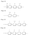
- Fig. 13 is a schematic drawing showing the system for exhaust gas purification used in Example 15.
- Fig. 14 is a schematic drawing showing the system for exhaust gas purification used in Comparative Example 1.
- Fig. 15 is a schematic drawing showing the system for exhaust gas purification used in Comparative Example 2.
- Fig. 16 is a schematic drawing showing the system for exhaust gas purification used in Comparative Example 3.
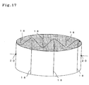
- Fig. 17 is a drawing showing an electrically-heated catalyst.
- the first system for exhaust gas purification is disposed in the exhaust pipe of an internal combustion engine and comprises:
- the loaded carrier has a primary purpose of reducing the thermal load applied to the adsorbent provided downstream thereof. That is, the heat of the exhaust gas is absorbed by the loaded carrier, whereby the excessive temperature increase of the downstream adsorbent is prevented and the thermal deterioration of the adsorbent is suppressed.
- the adsorbent used in the first system for exhaust gas purification is formed by loading, on a monolithic carrier, (1) a zeolite containing at least one kind of ion of an element having an electronegativity of 1.40 or more (the zeolite is hereinafter referred to as "ion-containing zeolite") and (2) a catalyst material formed by loading at least one kind of noble metal selected from Pt, Pd and Rh on a heat-resistant inorganic oxide.
- the ion of an element having an electronegativity of 1.40 or more includes ions of Al, Ti, V, Mn, Fe, Co, Ni, Cu, Zn, Pd, Ag, Pt, Au, etc.
- the above ion is at least one kind of ion of an element selected from 1B group elements (Cu, Ag and Au) of periodic table and is allowed to be present in zeolite, the ion can show high adsorptivity for HC even in the presence of moisture and, moreover, the ion exhibits even a catalytic activity at temperatures of 150°C or higher.
- 1B element ions Cu and Ag ions are preferred and Ag ion is particularly preferred because it can adsorb a larger amount of HC up to higher temperatures.
- Ag ion can show, even when O 2 is absent, the same adsorptivity as when O 2 is present; therefore, Ag ion shows excellent adsorptivity even when subjected to, for example, a fuel-rich atmosphere in automobile exhaust gas system.
- the content of ion in zeolite is small, its effect on increase in HC desorption start temperature is low.
- the content of ion in zeolite is preferably 20% or more, more preferably 40% or more based on the Al atoms in zeolite.
- a high-silica zeolite having a SiO 2 /Al 2 O 3 molar ratio of 40 or more, preferably 70 or more, more preferably 100 or more, in view of the heat resistance.
- the zeolite had better have a smaller SiO 2 /Al 2 O 3 molar ratio; however, use of a high-silica zeolite is preferred for the prevention of the thermal deterioration of zeolite.
- zeolite usable ZSM-5, USY, ⁇ -zeolite, a metallosilicate, ferrierite, mordenite and erionite. These zeolites can be used singly or in combination of two or more kinds.
- ZSM-5 having relatively small pores of about 0.55 nm in diameter is advantageous for adsorption of HC of small molecule having an effective toluene molecular diameter or smaller; USY having relatively large pores of about 0.74 nm in diameter is advantageous for adsorption of HC of large molecule having an effective m-xylene molecular diameter or larger; and ⁇ -zeolite having bimodal pores of about 0.55 nm and about 0.70 nm in diameter is advantageous in that it can relatively well adsorb both small molecule HC and large molecule HC.
- a plurality of zeolites having different pore diameters in any combination allows for efficient adsorption of various hydrocarbons of different effective molecular diameters.
- a plurality of different zeolites when used in combination, they can be loaded on a monolithic carrier in a mixed state or in a state of laminated layers, or can be loaded apart on the different parts (i.e. the upstream and downstream parts) of a monolithic carrier; or, they can be loaded on respective monolithic carriers and the loaded carriers can be used in combination.
- the catalyst material to be loaded on a monolithic carrier together with the ion-containing zeolite is formed by loading at least one noble metal selected from Pt, Pd and Rh, on a heat-resistant inorganic oxide.
- Pd is preferred for its excellent low-temperature light-off property.
- at least part of the catalyst material is a material formed by loading Pd on a heat-resistant inorganic oxide in an amount of 1-30% by weight, preferably 2-10% by weight based on the inorganic oxide.
- the heat-resistant inorganic oxide on which a noble metal(s) is (are) loaded there can be suitably used active alumina, zirconia, silica, titania, etc. Of these, active alumina and/or zirconia is preferred in view of the interaction with the noble metal(s).
- active alumina having a specific surface area of 100 m 2 /g or more
- a noble metal(s) is (are) loaded thereon in a highly dispersed state, whereby preferable catalytic activity is expressed.
- Zirconia when used in combination with Rh, provides improved heat resistance particularly in an oxidizing atmosphere.
- a rare earth element oxide a compound oxide of rare earth element oxides or a compound oxide of a rare earth element oxide and zirconia.
- the rare earth element oxide to be added to the heat-resistant inorganic oxide there can be suitably used CeO 2 , La 2 O 3 , a compound oxide thereof, etc.
- the addition of such a rare earth element oxide provides a catalyst of higher oxygen storage capacity (OSC) and wider three-way catalytic performance.
- the addition of a rare earth element oxide to a heat-resistant inorganic oxide may be conducted by adding a CeO 2 powder to active alumina.
- it can be conducted particularly preferably by impregnating active alumina with a cerium compound, calcinating the impregnated alumina to form an active alumina-ceria compound oxide, and adding thereto a CeO 2 powder as necessary, because this practice can improve the heat resistance of active alumina and the OSC of ceria.
- addition of CeO 2 to a heat-resistant inorganic oxide had better be avoided when Rh is loaded on the inorganic oxide, because the properties of Rh are impaired by the coexistence of CeO 2 .
- the monolithic carrier on which the ion-containing zeolite and the catalyst material are to be loaded is a structure having passages (cells) surrounded by substantially uniform partition walls, which is generally called a honeycomb structure.
- a honeycomb structure As the material for the monolithic carrier, there are suitably used ceramic materials made of cordierite, mullite or the like; foil-shaped metallic materials made of heat-resistant stainless steel (e.g. Fe-Cr-Al alloy); and metallic materials molded into a honeycomb structure by powder metallurgy.
- the ion-containing zeolite and the catalyst material are loaded on the monolithic carrier preferably in a mixed state in view of their mutual contact in the resulting adsorbent; however, they are loaded preferably in a state of laminated layers in view of the durability of the adsorbent.
- the surface layer is a layer of the catalyst material because the HC desorbed from the ion-containing zeolite can be effectively purified by the surface layer which is a layer of the catalyst material.
- the HC desorbed form the ion-containing zeolite of the adsorbent is purified only by the catalyst material of the adsorbent; in this case, therefore, it is essential that the catalyst material layer is formed as the surface layer of the adsorbent.
- the loaded carrier provided upstream of the adsorbent is formed by loading, on a monolithic carrier, a catalyst component having a purifiability for the harmful substances present in the exhaust gas emitted from an internal combustion engine and/or an adsorbent component having an adsorptivity for the hydrocarbons also present in the exhaust gas.
- the loaded carrier has no restriction as to its number but must have a total volume of 0.6 l or more, preferably 1.0 l or more.
- the volume of the loaded carrier refers to a volume of the monolithic carrier used in the loaded carrier, as defined by its contour, including the passages (cells) formed in the carrier.
- the loaded carrier having a total volume such as mentioned above is provided upstream of the adsorbent to reduce the thermal load applied to the adsorbent.
- the loaded carrier has a total volume of smaller than 0.6 l, the thermal load of the adsorbent is not sufficiently reduced and the thermal deterioration of the adsorbent cannot be suppressed effectively.
- the loaded carrier may be a catalyst obtained by loading a catalyst component alone on a monolithic carrier, or an adsorbent formed by loading an adsorbent component alone on a monolithic carrier, or a catalyst-adsorbent formed by loading a catalyst component and an adsorbent component on a monolithic carrier, or any combination thereof having a total volume of 0.6 l or more.
- the loaded carrier not only reduces the thermal load applied to the adsorbent but also exhibits a catalytic activity and/or an adsorptivity by itself.
- the loaded carrier When the loaded carrier is a catalyst or a catalyst-adsorbent, it can exhibit a light-off property at an early timing because it is provided at the most upstream position of the first system where the exhaust gas temperature is high, whereby the harmful substances present in the exhaust gas can be purified effectively.
- the loaded carrier When the loaded carrier is an adsorbent or a catalyst-adsorbent, this loaded carrier and the adsorbent provided downstream thereof can totally have a large capacity for HC adsorption.
- the loaded carrier In order to allow the loaded carrier per se to show a sufficient action, the loaded carrier preferably has a total volume of 1.5 l or more. In order for the loaded carrier to be able to show the effect over a long period of time, the loaded carrier preferably has a total volume of 2.0 l or more.
- the first system for exhaust gas purification according to the present invention can exhibit an excellent purifiability to the harmful substances present in the exhaust gas emitted from an internal combustion engine, particularly the HC discharged in a large amount during the cold start of the engine, over a long period of time.
- the adsorbent component loaded on the monolithic carrier can be a zeolite or a combination of a. plurality of zeolites as in the above-mentioned adsorbent provided downstream of a loaded carrier.
- the zeolite(s) can be the same or different from the zeolite(s) used in the adsorbent provided downstream of the loaded carrier. Further, the zeolite(s) may be present together with a catalyst material formed by loading a noble metal on a heat-resistant inorganic oxide, or may contain such a noble metal therein.
- the adsorbent or the catalyst-adsorbent used as the loaded carrier provided at the upstream position of the first system for exhaust gas purification must have heat resistance; therefore, the adsorbent or the catalyst-adsorbent should not contain, as the adsorbent component, an ion-containing zeolite of low heat resistance such as used in the adsorbent provided downstream of the loaded carrier.
- the zeolite(s) contained in the adsorbent or the catalyst-adsorbent preferably has (have) a high SiO 2 /Al 2 O 3 molar ratio.
- the catalyst component loaded on the monolithic carrier can be at least one noble metal selected from Pt, Pd, Rh, etc. with Pd being particularly preferred.
- Pd being particularly preferred.
- at least one of a plurality of the catalysts or catalyst-adsorbents contain Rh as the catalyst component in order to reduce not only the HC emitted during cold start but also NO x .
- the noble metal(s) may be used by being loaded on a heat-resistant inorganic oxide, as in the catalyst material used in the adsorbent provided downstream of the loaded carrier.
- the heat-resistant inorganic oxide may be added a rare earth element oxide, a compound oxide of rare earth element oxides, or a compound oxide of a rare earth element oxide and zirconia, in order to allow the loaded carrier to have an increased oxygen storage capacity (OSC).
- the catalyst or catalyst-adsorbent as loaded carrier provided at the upstream position of the first system is disposed preferably in the vicinity of engine wherein the exhaust gas temperature is high, for example, within 1,000 mm from the exhaust port of engine, in order to obtain a high purification efficiency.
- the loaded carrier When the loaded carrier is a catalyst-adsorbent, it can be formed by loading, on a monolithic carrier, a catalyst component and an adsorbent component in a mixed state or in a state of laminated layers, as in the case of forming the adsorbent provided downstream of the loaded carrier, by loading an ion-containing zeolite and a catalyst material on a monolithic carrier.
- the second system for exhaust gas purification is disposed in the exhaust pipe of an internal combustion engine and comprises:
- At least one kind of noble metal is not loaded on a heat-resistant inorganic oxide unlike in the adsorbent of the first system and is contained in a zeolite together with at least one kind of ion of an element having an electronegativity of 1.40 or more.
- the at least one kind of noble metal is selected from Pt, Pd and Rh with Pd being particularly preferred for the excellency in low-temperature light-off property.
- the kind of the zeolite used in the adsorbent of the second system is the same as in the adsorbent of the first system.
- the loaded carrier has a primary purpose of reducing the thermal load applied to the adsorbent provided downstream thereof, and it has the same constitution as the loaded carrier of the first system.
- the third system for exhaust gas purification is disposed in the exhaust pipe of an internal combustion engine and comprises:
- the adsorbent of the third system need not contain any noble metal required in the adsorbents of the first and second systems.
- the adsorbent using an ion-containing zeolite has a basic function of HC adsorption alone and the HC desorbed from the adsorbent is purified by a catalyst provided downstream of the adsorbent.
- the catalyst provided downstream of the adsorbent using an ion-containing zeolite is formed by loading, on a monolithic carrier, a catalyst material formed by loading at least one noble metal selected from Pt, Pd and Rh on a heat-resistant inorganic oxide.
- the details of the catalyst material used in the catalyst are the same as those of the catalyst material used in the adsorbent of the first system.
- the adsorbent and the catalyst provided downstream thereof are produced ordinarily using separate monolithic carriers; however, the adsorbent and the catalyst may be formed in one piece by loading an ion-containing zeolite and a catalyst material apart on one monolithic carrier, i.e. on the upstream and downstream positions of the monolithic carrier.
- the kind of the zeolite used in the adsorbent of the third system is the same as in the adsorbent of the first system.
- the loaded carrier has a primary purpose of reducing the thermal load applied to the adsorbent provided downstream thereof, and it has the same constitution as the loaded carrier of the first system.
- adsorbents, loaded carriers, etc. constituting the first to third systems for exhaust gas purification
- when at least one kind of noble metal is allowed to be present in a heat-resistant inorganic oxide or a zeolite it is preferred to allow a heat-resistant inorganic oxide or a zeolite to contain at least one kind of noble metal and then load the resulting material on a monolithic carrier, because this practice can produce an adsorbent, a loaded carrier or the like each of higher heat resistance.
- the noble metals or ions may be allowed to be present each in a different zeolite (these zeolites may be the same kind or different kinds) and the resulting materials may be loaded on one monolithic carrier; alternatively, the noble metals or ions may be allowed to be present in one zeolite simultaneously or in order and the resulting material may be loaded on a monolithic carrier.
- the at least one kind of ion can be allowed to be present in zeolite by ion exchange, impregnation or other method. Of them, ion exchange is preferred in view of the thermal stability of the resulting adsorbent.
- ion exchange is preferred in view of the thermal stability of the resulting adsorbent.
- all the ions may be allowed to be present by one method or by two or more different methods.
- the ion exchange rate can be increased by increasing the concentration of the metal salt solution used in ion exchange, or by taking a longer time for ion exchange.
- the ion exchange rate can be increased by increasing the times of ion exchange with new solution.
- At least one of a plurality of the loaded carriers provided at the upstream position of each system is preferably a catalyst or a catalyst-adsorbent, particularly preferably a catalyst. In a preferred embodiment, all the loaded carriers are catalysts.
- a catalyst may be provided downstream of the adsorbent (using an ion-containing zeolite) in the first or second system, or downstream of the catalyst provided downstream of the adsorbent (using an ion-containing zeolite) in the third system.
- the adsorbent or the loaded carrier when a catalyst is provided downstream of the adsorbent using an ion-containing zeolite or downstream of the loaded carrier used as an adsorbent or catalyst-adsorbent, it is preferred to (1) allow the adsorbent or the loaded carrier to have a portion of low pressure loss by changing the length or porosity of part of the adsorbent or the loaded carrier or (2) form, in the adsorbent or the loaded carrier, a blowing-through hole having a diameter larger than the diameter of the passages (cells) of the monolithic carrier, to allow part of the exhaust gas to blow through the hole, because (1) or (2) accelerates the warm-up of the catalyst provided downstream of the adsorbent or the loaded carrier and enhances the efficiency of purification of desorbed HC.
- the diameter of the blowing-through hole is preferably 50 mm or less in view of the strength of carrier; the diameter is more preferably 40 mm or less in order to prevent the reduction in amount of HC adsorption, caused by blowing-through of excessive amount of exhaust gas. Conversely, when the diameter of the blowing-through hole is too small, the warm-up of the catalyst provided downstream of the adsorbent or the loaded carrier is insufficient. Therefore, the diameter is preferably 10 mm or more.
- At least one electrical heater (hereinafter referred to as "EH") is disposed in the same exhaust line in order to achieve the early activation of the catalyst.
- the EH is preferably constituted by a honeycomb structure made of a heat-resistant metal (e.g. ferrite) and electrodes attached to the honeycomb structure for electrification thereof, in view of the pressure loss and heat resistance.
- This EH is preferably used in the form of an electrically-heated catalyst (hereinafter referred to as "EHC") which comprises the EH and a catalyst layer formed thereon, made of a noble metal-containing heat-resistant inorganic oxide, because, with the EHC, the electricity required for heating of EH can be reduced owing to the reaction heat of catalyst.
- EHC electrically-heated catalyst
- the EHC may be provided upstream of the system to accelerate the warm-up of the system, or downstream of the adsorbent using an ion-containing zeolite, to ensure the purification of the HC desorbed from the adsorbent.
- an oxidizing gas e.g. secondary air
- the ratio of the amount of air for combustion and the amount of fuel is changed so as to increase the oxygen amount in exhaust gas, the combustion reaction on catalyst is promoted and the early light-off of catalyst is achieved.
- the above introduction of oxidizing gas or the above change of the ratio of the amount of air for combustion and the amount of fuel for increased oxygen supply is preferred because as the HC adsorbed on the adsorbent begins to be desorbed with the temperature rise of the adsorbent caused by the heat of exhaust gas, the HC concentration in exhaust gas increases and the oxygen required for purification (combustion) of HC becomes short.
- the present system for exhaust gas purification functions satisfactorily by applying one system to one internal combustion engine.
- each one system may be applied to each bank.
- At least one loaded carrier having a given total volume is provided upstream of an adsorbent using an ion-containing zeolite, in order to reduce the thermal load applied to the adsorbent.
- This reduction in the thermal load is also possible by other methods, for example, by (1) providing the adsorbent at a position as far as possible from the internal combustion engine or (2) providing a cooling (water cooling or air cooling) means between the internal combustion engine and the adsorbent.
- a cooling water cooling or air cooling
- the provision of a loaded carrier containing a catalyst component and/or an adsorbent component, upstream of an adsorbent using an ion-containing zeolite is most preferred because it can not only reduce the thermal load applied to the adsorbent but also utilize the effect of the loaded carrier per se, i.e. the purification and/or adsorption effect.
- the method (1) and/or the method (2) may be employed in combination with the present system to obtain a higher reduction in the thermal load applied to the adsorbent.
- a commercial ⁇ -Al 2 O 3 having a specific surface area of 200 m 2 /g was impregnated with a noble metal (Pd or Rh) by the use of an aqueous Pd(NO 3 ) 2 solution or an aqueous Rh(NO 3 ) 3 solution.
- the resulting material was dried and then fired at 500°C to obtain a Pd-loaded Al 2 O 3 powder and a Rh-loaded Al 2 O 3 powder.
- To the Pd-loaded Al 2 O 3 powder was further added 30% by weight of a CeO 2 powder.
- the Pd-loaded Al 2 O 3 •CeO 2 slurry was coated on a cordierite monolithic carrier manufactured by NGK Insulators, Ltd. (diameter: 3.66 in., volume: 0.5 l, partition wall thickness: 6 mil, cell density: 400 cpi 2 ) in a Pd amount of 100 g/ft 3 .
- the coated carrier was fired at 500°C to obtain catalyst Al.
- the Pd-loaded Al 2 O 3 •CeO 2 slurry was also coated on a cordierite monolithic carrier manufactured by NGK Insulators, ltd. (diameter: 4.66 in., volume: 1.0 l, partition wall thickness: 6 mil, cell density: 400 cpi 2 ) in a Pd amount of 100 g/ft 3 .
- the coated carrier was fired at 500°C.
- Rh-loaded Al 2 O 3 slurry in a Rh amount of 10 g/ft 3 , and the resulting material was fired at 500°C to obtain catalyst A2.
- Catalyst-adsorbent C2 was obtained in the same manner as in the catalyst-adsorbent C1 except that, in the uncoated monolithic carrier, a blowing-through hole was made (the monolithic carrier after hole making had a volume of 0.95 l) by gouging a cylindrical portion of the carrier, having a diameter of 25 mm, whose central axis was identical with that of the carrier and which extended in the axial direction of the passages (cells) of the carrier.
- Desired amounts of a zeolite powder, a metal salt and deionized water were each weighed, and they were mixed so as to give a metal salt concentration in solution, of 0.05-0.2 mole/l.
- the resulting solution was kept at 80-90°C and subjected to ion exchange for 2 hours (per each ion exchange) with stirring. After filtration, ion exchange was conducted again with a new solution, and this filtration and subsequent ion exchange with new solution was repeated 3-5 times. Then, washing was conducted with deionized water at 50°C for 15 minutes (per each washing), followed by filtration. This washing and filtration was repeated 5-10 times.
- the resulting material was dried in air at 100°C for 10 hours and then calcinated in air at 550°C for 1 hour to obtain three kinds of zeolite powders each subjected to ion exchange with a desired ion.
- Zeolite Metal salt Ion exchange rate Ag ion-exchanged ZSM-5 powder ZSM-5 CH 3 COOAg 80% Cu ion-exchanged ZSM-5 powder ZSM-5 Cu(CH 3 COO) 2 .H 2 O 85% Ag ion-exchanged ⁇ -zeolite powder ⁇ -Zeolite CH 3 COOAg 82%
- zeolite powders obtained above were added appropriate amounts of water and acetic acid. Thereto was added 5% by weight (as oxide) of an Al 2 O 3 sol. The resulting mixture was subjected to wet pulverization to prepare three kinds of slurries to be coated. Each of the slurries was coated on a cordierite monolithic carrier manufactured by NGK Insulators, Ltd. (diameter: 4.66 in., volume: 1.0 l, partition wall thickness: 6 mil, cell density: 400 cpi 2 ).
- Each of the coated carriers was fired at 500°C to obtain adsorbent D1 (containing Ag ion-exchanged ZSM-5), adsorbent D2 (containing Cu ion-exchanged ZSM-5), and adsorbent D3 (containing Ag ion-exchanged ⁇ -zeolite).
- the amount of zeolite loaded was 0.15 g/cc.
- Adsorbent D4 was obtained in the same manner as in adsorbent D1 except that, in the uncoated monolithic carrier, a blowing-through hole was made (the monolithic carrier after hole making had a volume of 0.95 l) by gouging a cylindrical portion of the carrier, having a diameter of 25 mm, whose central axis was identical with that of the carrier and which extended in the axial direction of the passages (cells) of the carrier.
- Adsorbent D5 was obtained by coating, on the adsorbent D1, the same Pd-loaded Al 2 O 3 .CeO 2 slurry as used in the above [Production of catalysts], in a Pd amount of 100 g/ft 3 and then firing the resulting material at 500°C.
- the Ag ion-exchanged ZSM-5 powder was immersed in an aqueous Pd(NO 3 ) solution, followed by drying and firing at 500°C, to obtain a Pd-loaded, Ag ion-exchanged ZSM-5 powder.
- To the zeolite powder were added appropriate amounts of water and acetic acid. Thereto was added 5% by weight (as oxide) of an Al 2 O 3 sol.
- the resulting mixture was subjected to wet pulverization to prepare a slurry to be coated.
- the slurry was coated on a cordierite monolithic carrier manufactured by NGK Insulators, Ltd. (diameter: 4.66 in., volume: 1.0 l, partition wall thickness: 6 mil, cell density: 400 cpi 2 ).
- the coated carrier was fired at 500°C to obtain adsorbent D6.
- the amount of zeolite loaded was 0.15 g/cc; and the amount of Pd loaded was 100 g/ft 3 , which was achieved by controlling the concentration of the aqueous Pd(NO 3 ) solution at the time of immersion of the Ag ion-exchanged ZSM-5 powder in the solution.
- honeycomb material was dried at 90°C for 16 hours in air and then kept at 1,325°C for 2 hours in a hydrogen atmosphere for sintering.
- the sintered material was heat-treated at 1,150°C for 30 minutes in air to obtain a honeycomb structure.
- the honeycomb structure had a porosity of 3%.
- the thus-obtained honeycomb structure having an outer diameter of 93 mm, a thickness of 25 mm, a partition wall thickness of 0.1 mm and a cell (square cell) density of 450 cpi 2 was subjected to grinding by hand saw to form, as shown in Fig. 17, six slits 18 in a direction parallel to the axes of the passages of the honeycomb structure so that the number of cells between two adjacent slits became seven and the honeycomb structure after slits formation had an electrical resistance of 50 m ⁇ .
- catalyst A2 (2) and adsorbent D5 (10) were disposed in this order with catalyst A2 (2) provided upstream in the flow direction of exhaust gas.
- the distance from the inlet of catalyst A2 (2) to the inlet of adsorbent D5 (10) was 200 mm.
- catalyst A2 (2) and adsorbent D6 (11) were disposed in this order with catalyst A2 (2) provided upstream in the flow direction of exhaust gas.
- the distance from the inlet of catalyst A2 (2) to the inlet of adsorbent D6 (11) was 200 mm.
- catalyst A2 (2), adsorbent D1 (6) and catalyst A1 (1) were disposed in this order with catalyst A2 (2) provided most upstream in the flow direction of exhaust gas.
- the distance from the inlet of catalyst A2 (2) to the inlet of adsorbent D1 (6) was 200 mm; and the distance from the inlet of catalyst A2 (2) to the inlet of catalyst Al (1) was 400 mm.
- catalyst-adsorbent C1 (4) and adsorbent D5 (10) were disposed in this order with catalyst-adsorbent C1 (4) provided upstream in the flow direction of exhaust gas.
- the distance from the inlet of catalyst-adsorbent C1 (4) to the inlet of adsorbent D5 (10) was 200 mm.
- catalyst-adsorbent C2 (5) and adsorbent D5 (10) were disposed in this order with catalyst-adsorbent C2 (5) provided upstream in the flow direction of exhaust gas.
- the distance from the inlet of catalyst-adsorbent C2 (5) to the inlet of adsorbent D5 (10) was 200 mm.
- catalyst A1 (1), catalyst A2 (2) and adsorbent D5 (10) were disposed in this order with catalyst A1 (1) provided most upstream in the flow direction of exhaust gas.
- the distance from the inlet of catalyst Al (1) to the inlet of catalyst A2 (2) was 200 mm; and the distance from the inlet of catalyst Al (1) to the inlet of adsorbent D5 (10) was 400 mm.
- catalyst A1 (1), catalyst A2 (2), adsorbent D5 (10) and catalyst A1 (1') were disposed in this order with catalyst A1 (1) provided most upstream in the flow direction of exhaust gas.
- the distance from the inlet of catalyst A1 (1) to the inlet of catalyst A2 (2) was 200 mm; the distance from the inlet of catalyst A1 (1) to the inlet of adsorbent D5 (10) was 400 mm; and the distance from the inlet of catalyst A1 (1) to the inlet of catalyst A1 (1') was 600 mm.
- catalyst Al (1), catalyst A2 (2), adsorbent D4 (9) and catalyst Al (1') were disposed in this order with catalyst A1 (1) provided most upstream in the flow direction of exhaust gas.
- the distance from the inlet of catalyst A1 (1) to the inlet of catalyst A2 (2) was 200 mm; the distance from the inlet of catalyst A1 (1) to the inlet of adsorbent D4 (9) was 400 mm; and the distance from the inlet of catalyst A1 (1) to the inlet of catalyst A1 (1') was 600 mm.
- catalyst A1 (1), catalyst A2 (2), adsorbent D2 (7) and catalyst A1 (1') were disposed in this order with catalyst A1 (1) provided most upstream in the flow direction of exhaust gas.
- the distance from the inlet of catalyst A1 (1) to the inlet of catalyst A2 (2) was 200 mm; the distance from the inlet of catalyst A1 (1) to the inlet of adsorbent D2 (7) was 400 mm; and the distance from the inlet of catalyst A1 (1) to the inlet of catalyst A1 (1') was 600 mm.
- catalyst A1 (1), catalyst A2 (2), adsorbent D3 (8) and catalyst A1 (1') were disposed in this order with catalyst A1 (1) provided most upstream in the flow direction of exhaust gas.
- the distance from the inlet of catalyst A1 (1) to the inlet of catalyst A2 (2) was 200 mm; the distance from the inlet of catalyst A1 (1) to the inlet of adsorbent D3 (8) was 400 mm; and the distance from the inlet of catalyst A1 (1) to the inlet of catalyst A1 (1') was 600 mm.
- catalyst A1 (1), adsorbent B1 (3), adsorbent D3 (8) and catalyst A1 (1') were disposed in this order with catalyst A1 (1) provided most upstream in the flow direction of exhaust gas.
- the distance from the inlet of catalyst A1 (1) to the inlet of adsorbent B1 (3) was 200 mm; the distance from the inlet of catalyst A1 (1) to the inlet of adsorbent D3 (8) was 400 mm; and the distance from the inlet of catalyst A1 (1) to the inlet of catalyst A1 (1') was 600 mm.
- catalyst A2 (2) and adsorbent D5 (10) were disposed in this order with catalyst A2 (2) provided upstream in the flow direction of exhaust gas.
- the distance from the inlet of catalyst A2 (2) to the inlet of adsorbent D5 (10) was 400 mm.
- adsorbent D5 (10) and catalyst A2 (2) were disposed in this order with adsorbent D5 (10) provided upstream in the flow direction of exhaust gas.
- the distance from the inlet of adsorbent D5 (10) to the inlet of catalyst A2 (2) was 200 mm.
- catalyst A1 (1), adsorbent D5 (10), catalyst A2 (2) and catalyst A1 (1') were disposed in this order with catalyst A1 (1) provided most upstream in the flow direction of exhaust gas.
- the distance from the inlet of catalyst A1 (1) to the inlet of adsorbent D5 (10) was 200 mm; the distance from the inlet of catalyst A1 (1) to the inlet of catalyst A2 (2) was 400 mm; and the distance from the inlet of catalyst A1 (1) to the inlet of catalyst A1 (1') was 600 mm.
- catalyst A1 (1), catalyst A2 (2), adsorbent B1 (3), and catalyst A1 (1') were disposed in this order with catalyst A1 (1) provided most upstream in the flow direction of exhaust gas.
- the distance from the inlet of catalyst A1 (1) to the inlet of catalyst A2 (2) was 200 mm; the distance from the inlet of catalyst A1 (1) to the inlet of adsorbent B1 (3) was 400 mm; and the distance from the inlet of catalyst A1 (1) to the inlet of catalyst A1 (1') was 600 mm.
- Each of the systems I to XVII was set in the exhaust gas line of an actual engine so that the exhaust gas temperature at the inlet of the catalyst, adsorbent or catalyst-adsorbent of each system, provided at the most upstream position of the system became 850°C. Then, the engine was operated for 60 seconds at an A/F ratio close to the stoichiometric ratio (14.4). Thereafter, fuel feeding was cut for 5 seconds to shift the A/F ratio to a lean fuel side. In this engine operational mode including the above fuel-cutting, each system was subjected to aging for total 100 hours. Incidentally, in the case of the system XIII, adsorbent D5 was cooled during the aging, by the water-cooling device provided between catalyst A2 and adsorbent D5.
- Each system after the aging was disposed in the exhaust gas line of a L4 type engine of 2,000 cc displacement mounted on a vehicle, so that the inlet of the catalyst, adsorbent or catalyst-adsorbent of the system, provided at the most upstream position of the system was at a point of 700 mm from the engine exhaust port. Then, each system was subjected to a FTP and measured for HC emission (HC emission and NO x emission for part of the systems) according to Bag 1 which is an indication of cold start property. The results are shown in Table 3.
- Example 15 In the FTP of Example 15 using system XIV, electrically-heated catalyst El was electrified at 2 kW for 30 seconds from the engine start. In Example 13 using system XIII, adsorbent D5 was cooled during the FTP, by the water-cooling device provided between catalyst A2 and adsorbent D5.
- Example 14 secondary air was introduced into the systems. Except in Example 14, secondary air was introduced at a rate of 100 l/min for 0 to 100 seconds from the engine start and at a rate of 50 l/min for 100 to 250 seconds from the engine start, from an exhaust pipe position of 200 mm from the engine exhaust port. In Example 14, secondary air was introduced at a rate of 100 l/min for 0 to 100 seconds from the engine start from an exhaust pipe position of 200 mm from the engine exhaust port and at a rate of 50 l/min for 100 to 250 seconds from the engine start from between catalyst A2 and adsorbent D5.
- Examples 1 to 15 each using a system comprising (1) an adsorbent using an ion-containing zeolite, i.e. either of D1 to D6 and (2) a loaded carrier (a catalyst, an adsorbent and/or an adsorbent-catalyst) having a total volume of 0.6 l or more, provided upstream of the adsorbent (1) showed low HC emissions as compared with Comparative Example 1 using a system comprising no loaded carrier upstream of an adsorbent using an ion-containing zeolite, or with Comparative Example 2 using a system comprising a loaded carrier having a total volume of less than 0.6 l, upstream of an adsorbent using an ion-containing zeolite, or with Comparative Example 3 using a system comprising no adsorbent using an ion-containing zeolite.
- a loaded carrier a catalyst, an adsorbent and/or an adsorbent-catalyst
- HC emissions were particularly low in Examples 6 to 11 and 15 each using a system comprising a loaded carrier having a larger total volume (i.e. a larger total heat capacity), upstream of an adsorbent using an ion-containing zeolite.
- NO x emission also decreased in Example 14 wherein the position of secondary air introduction was changed, in the middle, from upstream of catalyst A2 to between catalyst A2 and adsorbent D5, because catalyst A2 was released from a lean atmosphere soon after the light-off.
- the exhaust gas purification system of the present invention comprising (1) an adsorbent using a zeolite containing an ion of an element having an electronegativity of 1.40 or more (such a zeolite per se has a high HC desorption start temperature but low heat resistance and accordingly its practical use has been difficult) and (2) a loaded carrier of given volume provided upstream of the adsorbent (1), the thermal load of the adsorbent is reduced and the performance of the adsorbent is maintained over a long period of time. Moreover, since the loaded carrier has per se an HC adsorptivity and a purifiability for the harmful substances present in exhaust gas, the present system has a high overall purification ability.
- the invention is especially applicable in an in-line type exhaust system, having all components in a single unbranched pipe.
Landscapes
- Engineering & Computer Science (AREA)
- Chemical & Material Sciences (AREA)
- Combustion & Propulsion (AREA)
- Mechanical Engineering (AREA)
- General Engineering & Computer Science (AREA)
- Chemical Kinetics & Catalysis (AREA)
- Environmental & Geological Engineering (AREA)
- Biomedical Technology (AREA)
- Health & Medical Sciences (AREA)
- Analytical Chemistry (AREA)
- General Chemical & Material Sciences (AREA)
- Oil, Petroleum & Natural Gas (AREA)
- Exhaust Gas After Treatment (AREA)
- Exhaust Gas Treatment By Means Of Catalyst (AREA)
- Catalysts (AREA)
- Treating Waste Gases (AREA)
- Solid-Sorbent Or Filter-Aiding Compositions (AREA)
Applications Claiming Priority (4)
| Application Number | Priority Date | Filing Date | Title |
|---|---|---|---|
| JP158944/97 | 1997-06-16 | ||
| JP15894497 | 1997-06-16 | ||
| JP9158944A JPH115020A (ja) | 1997-06-16 | 1997-06-16 | 排ガス浄化システム |
| US09/093,789 US6350416B2 (en) | 1997-06-16 | 1998-06-09 | System for exhaust gas purification |
Publications (3)
| Publication Number | Publication Date |
|---|---|
| EP0886041A2 true EP0886041A2 (fr) | 1998-12-23 |
| EP0886041A3 EP0886041A3 (fr) | 2001-09-19 |
| EP0886041B1 EP0886041B1 (fr) | 2004-01-28 |
Family
ID=26485907
Family Applications (1)
| Application Number | Title | Priority Date | Filing Date |
|---|---|---|---|
| EP98304680A Expired - Lifetime EP0886041B1 (fr) | 1997-06-16 | 1998-06-12 | Système pour la purification des gazs d'échappement |
Country Status (4)
| Country | Link |
|---|---|
| US (1) | US6350416B2 (fr) |
| EP (1) | EP0886041B1 (fr) |
| JP (1) | JPH115020A (fr) |
| CA (1) | CA2240691C (fr) |
Cited By (2)
| Publication number | Priority date | Publication date | Assignee | Title |
|---|---|---|---|---|
| DE10023049A1 (de) * | 2000-05-11 | 2001-11-15 | Volkswagen Ag | Abgasreinigungsanlage für eine direkteinspritzende und magerlauffähige Verbrennungskraftmaschine und Verfahren zur Bestimmung eines Montagepunktes eines Vorkatalysators im Abgasstrang der Verbrennungskraftmaschine |
| EP1721665A1 (fr) * | 2005-05-13 | 2006-11-15 | HTE Aktiengesellschaft The High Throughput Experimentation Company | Catalyseur pour le traitement d'un gaz d'échappe et un procédé pour sa préparation |
Families Citing this family (11)
| Publication number | Priority date | Publication date | Assignee | Title |
|---|---|---|---|---|
| JP4703818B2 (ja) * | 2000-06-20 | 2011-06-15 | 株式会社アイシーティー | 排気ガス浄化用触媒および排気ガス浄化方法 |
| US7795172B2 (en) * | 2004-06-22 | 2010-09-14 | Basf Corporation | Layered exhaust treatment catalyst |
| GB0508636D0 (en) * | 2005-04-28 | 2005-06-08 | Smiths Group Plc | Molecular sieves |
| US7682577B2 (en) * | 2005-11-07 | 2010-03-23 | Geo2 Technologies, Inc. | Catalytic exhaust device for simplified installation or replacement |
| US8580228B2 (en) | 2006-12-27 | 2013-11-12 | Chevron U.S.A. Inc. | Treatment of cold start engine exhaust |
| WO2009141895A1 (fr) * | 2008-05-20 | 2009-11-26 | イビデン株式会社 | Appareil de purification de gaz d'échappement |
| DE102008055890A1 (de) * | 2008-11-05 | 2010-05-12 | Süd-Chemie AG | Partikelminderung mit kombiniertem SCR- und NH3-Schlupf-Katalysator |
| DE112017001786T5 (de) * | 2016-03-31 | 2018-12-13 | Ngk Insulators, Ltd. | Monolithische Trennmembranstruktur |
| CN110075909A (zh) * | 2019-04-10 | 2019-08-02 | 中国船舶重工集团公司第七一八研究所 | 一种净化含氮有机化合物废气用催化剂 |
| WO2021201018A1 (fr) | 2020-03-31 | 2021-10-07 | 東ソー株式会社 | Adsorbant d'hydrocarbures et procédé d'adsorption d'hydrocarbures |
| CN117145619A (zh) * | 2023-07-20 | 2023-12-01 | 浙江吉利控股集团有限公司 | 一种尾气处理系统、方法及车辆 |
Family Cites Families (9)
| Publication number | Priority date | Publication date | Assignee | Title |
|---|---|---|---|---|
| JPH0559942A (ja) | 1991-08-29 | 1993-03-09 | Toyota Motor Corp | コールドhc吸着除去装置 |
| JPH0557148A (ja) | 1991-09-04 | 1993-03-09 | Nissan Motor Co Ltd | 排気ガス浄化用触媒装置 |
| US5303547A (en) * | 1992-04-15 | 1994-04-19 | Amoco Corporation | Emissions control system and method |
| EP0593898B1 (fr) | 1992-10-20 | 1997-01-29 | Corning Incorporated | Procédé de conversion de gaz d'échappement et disposition utilisant des zéolites thermiquement stables |
| JPH06272542A (ja) * | 1993-03-17 | 1994-09-27 | Hitachi Ltd | 内燃機関の排気浄化制御装置及び制御方法 |
| JP3526084B2 (ja) * | 1993-12-28 | 2004-05-10 | 日本碍子株式会社 | 排ガス浄化用吸着・触媒体、吸着体、排ガス浄化システム及び排ガス浄化方法 |
| JP3516718B2 (ja) | 1994-07-05 | 2004-04-05 | 日本碍子株式会社 | 排ガス浄化用触媒−吸着体及び排ガス浄化方法 |
| JPH0810613A (ja) | 1994-07-05 | 1996-01-16 | Ngk Insulators Ltd | 自動車排ガス浄化用吸着材 |
| US5510086A (en) * | 1995-04-10 | 1996-04-23 | General Motors Corporation | Adcat exhaust treatment device |
-
1997
- 1997-06-16 JP JP9158944A patent/JPH115020A/ja active Pending
-
1998
- 1998-06-09 US US09/093,789 patent/US6350416B2/en not_active Expired - Fee Related
- 1998-06-12 EP EP98304680A patent/EP0886041B1/fr not_active Expired - Lifetime
- 1998-06-15 CA CA002240691A patent/CA2240691C/fr not_active Expired - Fee Related
Cited By (5)
| Publication number | Priority date | Publication date | Assignee | Title |
|---|---|---|---|---|
| DE10023049A1 (de) * | 2000-05-11 | 2001-11-15 | Volkswagen Ag | Abgasreinigungsanlage für eine direkteinspritzende und magerlauffähige Verbrennungskraftmaschine und Verfahren zur Bestimmung eines Montagepunktes eines Vorkatalysators im Abgasstrang der Verbrennungskraftmaschine |
| FR2808840A1 (fr) * | 2000-05-11 | 2001-11-16 | Volkswagen Ag | Procede de determination du point de montage d'un precatalyseur dans la tubulure d'echappement d'un moteur a combustion interne et installation d'epuration l'utilisant |
| DE10023049B4 (de) * | 2000-05-11 | 2008-04-30 | Volkswagen Ag | Verfahren zur Bestimmung eines Montagepunktes eines Vorkatalysators im Abgasstrang der Verbrennungskraftmaschine |
| EP1721665A1 (fr) * | 2005-05-13 | 2006-11-15 | HTE Aktiengesellschaft The High Throughput Experimentation Company | Catalyseur pour le traitement d'un gaz d'échappe et un procédé pour sa préparation |
| WO2006120013A1 (fr) * | 2005-05-13 | 2006-11-16 | Hte Aktiengesellschaft The High Throughput Experimentation Company | Catalyseur pour traitement des gaz d'echappement et procedes d'obtention |
Also Published As
| Publication number | Publication date |
|---|---|
| CA2240691C (fr) | 2003-04-22 |
| US6350416B2 (en) | 2002-02-26 |
| EP0886041B1 (fr) | 2004-01-28 |
| US20010002988A1 (en) | 2001-06-07 |
| CA2240691A1 (fr) | 1998-12-16 |
| EP0886041A3 (fr) | 2001-09-19 |
| JPH115020A (ja) | 1999-01-12 |
Similar Documents
| Publication | Publication Date | Title |
|---|---|---|
| EP0904827A1 (fr) | Catalyseur-absorbant pour la purification des gaz d'échappement et procédé de purification des gaz d'échappement | |
| CA2224043C (fr) | Methode d'epuration des gaz d'echappement et systeme utilise | |
| EP0782880B1 (fr) | Catalyseur-adsorbant pour la purification des gaz d'échappement et procédé de purification des gaz d'échappement | |
| US6667018B2 (en) | Catalyst-adsorbent for purification of exhaust gases and method for purification of exhaust gases | |
| EP0820810B1 (fr) | Purification de gaz d'échappement | |
| EP0602963B1 (fr) | Méthode et dispositif pour la purification de gaz d'échappement | |
| EP2641651B1 (fr) | Filtre à suie catalysé, à pression autorégularisée | |
| US6500392B2 (en) | Catalyst for exhaust gas purification and system for exhaust gas purification | |
| US6139808A (en) | Catalyst for exhaust gas purification and system for exhaust gas purification | |
| EP0886041B1 (fr) | Système pour la purification des gazs d'échappement | |
| EP0935055A2 (fr) | Dispositif de purification de gaz d'échappement riche en oxygène | |
| US6602822B2 (en) | Catalyst for exhaust gas purification and exhaust gas purification system using the same | |
| EP0867218B1 (fr) | Moteur avec système de purification de gaz d'échappement | |
| EP0766994B1 (fr) | Dispositif pour la purification de gaz d'échappement | |
| CA2240704C (fr) | Systeme de purification des gaz d'echappement | |
| EP0895803B1 (fr) | Utilisation d'un dispositif pour purifier des gaz d'échappement |
Legal Events
| Date | Code | Title | Description |
|---|---|---|---|
| PUAI | Public reference made under article 153(3) epc to a published international application that has entered the european phase |
Free format text: ORIGINAL CODE: 0009012 |
|
| AK | Designated contracting states |
Kind code of ref document: A2 Designated state(s): AT BE CH CY DE DK ES FI FR GB GR IE IT LI LU MC NL PT SE Kind code of ref document: A2 Designated state(s): BE DE FR GB IT SE |
|
| AX | Request for extension of the european patent |
Free format text: AL;LT;LV;MK;RO;SI |
|
| PUAL | Search report despatched |
Free format text: ORIGINAL CODE: 0009013 |
|
| AK | Designated contracting states |
Kind code of ref document: A3 Designated state(s): AT BE CH CY DE DK ES FI FR GB GR IE IT LI LU MC NL PT SE |
|
| AX | Request for extension of the european patent |
Free format text: AL;LT;LV;MK;RO;SI |
|
| 17P | Request for examination filed |
Effective date: 20011015 |
|
| 17Q | First examination report despatched |
Effective date: 20011220 |
|
| AKX | Designation fees paid |
Free format text: BE DE FR GB IT SE |
|
| GRAP | Despatch of communication of intention to grant a patent |
Free format text: ORIGINAL CODE: EPIDOSNIGR1 |
|
| GRAS | Grant fee paid |
Free format text: ORIGINAL CODE: EPIDOSNIGR3 |
|
| GRAA | (expected) grant |
Free format text: ORIGINAL CODE: 0009210 |
|
| RBV | Designated contracting states (corrected) |
Designated state(s): BE DE FR GB |
|
| AK | Designated contracting states |
Kind code of ref document: B1 Designated state(s): BE DE FR GB |
|
| REG | Reference to a national code |
Ref country code: GB Ref legal event code: FG4D |
|
| REF | Corresponds to: |
Ref document number: 69821284 Country of ref document: DE Date of ref document: 20040304 Kind code of ref document: P |
|
| PGFP | Annual fee paid to national office [announced via postgrant information from national office to epo] |
Ref country code: GB Payment date: 20040602 Year of fee payment: 7 |
|
| PGFP | Annual fee paid to national office [announced via postgrant information from national office to epo] |
Ref country code: FR Payment date: 20040623 Year of fee payment: 7 |
|
| PGFP | Annual fee paid to national office [announced via postgrant information from national office to epo] |
Ref country code: BE Payment date: 20040630 Year of fee payment: 7 |
|
| ET | Fr: translation filed | ||
| PLBE | No opposition filed within time limit |
Free format text: ORIGINAL CODE: 0009261 |
|
| STAA | Information on the status of an ep patent application or granted ep patent |
Free format text: STATUS: NO OPPOSITION FILED WITHIN TIME LIMIT |
|
| 26N | No opposition filed |
Effective date: 20041029 |
|
| PG25 | Lapsed in a contracting state [announced via postgrant information from national office to epo] |
Ref country code: GB Free format text: LAPSE BECAUSE OF NON-PAYMENT OF DUE FEES Effective date: 20050612 |
|
| PG25 | Lapsed in a contracting state [announced via postgrant information from national office to epo] |
Ref country code: BE Free format text: LAPSE BECAUSE OF NON-PAYMENT OF DUE FEES Effective date: 20050630 |
|
| PG25 | Lapsed in a contracting state [announced via postgrant information from national office to epo] |
Ref country code: FR Free format text: LAPSE BECAUSE OF NON-PAYMENT OF DUE FEES Effective date: 20060228 |
|
| GBPC | Gb: european patent ceased through non-payment of renewal fee |
Effective date: 20050612 |
|
| REG | Reference to a national code |
Ref country code: FR Ref legal event code: ST Effective date: 20060228 |
|
| BERE | Be: lapsed |
Owner name: *NGK INSULATORS LTD Effective date: 20050630 |
|
| PGFP | Annual fee paid to national office [announced via postgrant information from national office to epo] |
Ref country code: DE Payment date: 20120629 Year of fee payment: 15 |
|
| REG | Reference to a national code |
Ref country code: DE Ref legal event code: R119 Ref document number: 69821284 Country of ref document: DE Effective date: 20140101 |
|
| PG25 | Lapsed in a contracting state [announced via postgrant information from national office to epo] |
Ref country code: DE Free format text: LAPSE BECAUSE OF NON-PAYMENT OF DUE FEES Effective date: 20140101 |