EP0886548B1 - Verfahren und vorrichtung zur trocknung und reinigung von gegenständen mittels aerosolen - Google Patents
Verfahren und vorrichtung zur trocknung und reinigung von gegenständen mittels aerosolen Download PDFInfo
- Publication number
- EP0886548B1 EP0886548B1 EP97916750A EP97916750A EP0886548B1 EP 0886548 B1 EP0886548 B1 EP 0886548B1 EP 97916750 A EP97916750 A EP 97916750A EP 97916750 A EP97916750 A EP 97916750A EP 0886548 B1 EP0886548 B1 EP 0886548B1
- Authority
- EP
- European Patent Office
- Prior art keywords
- chamber
- liquid
- rinse liquid
- selected liquid
- rinse
- Prior art date
- Legal status (The legal status is an assumption and is not a legal conclusion. Google has not performed a legal analysis and makes no representation as to the accuracy of the status listed.)
- Expired - Lifetime
Links
Images


Classifications
-
- B—PERFORMING OPERATIONS; TRANSPORTING
- B08—CLEANING
- B08B—CLEANING IN GENERAL; PREVENTION OF FOULING IN GENERAL
- B08B3/00—Cleaning by methods involving the use or presence of liquid or steam
- B08B3/04—Cleaning involving contact with liquid
-
- H—ELECTRICITY
- H10—SEMICONDUCTOR DEVICES; ELECTRIC SOLID-STATE DEVICES NOT OTHERWISE PROVIDED FOR
- H10P—GENERIC PROCESSES OR APPARATUS FOR THE MANUFACTURE OR TREATMENT OF DEVICES COVERED BY CLASS H10
- H10P70/00—Cleaning of wafers, substrates or parts of devices
- H10P70/10—Cleaning before device manufacture, i.e. Begin-Of-Line process
- H10P70/15—Cleaning before device manufacture, i.e. Begin-Of-Line process by wet cleaning only
-
- B—PERFORMING OPERATIONS; TRANSPORTING
- B08—CLEANING
- B08B—CLEANING IN GENERAL; PREVENTION OF FOULING IN GENERAL
- B08B3/00—Cleaning by methods involving the use or presence of liquid or steam
- B08B3/04—Cleaning involving contact with liquid
- B08B3/10—Cleaning involving contact with liquid with additional treatment of the liquid or of the object being cleaned, e.g. by heat, by electricity or by vibration
- B08B3/102—Cleaning involving contact with liquid with additional treatment of the liquid or of the object being cleaned, e.g. by heat, by electricity or by vibration with means for agitating the liquid
-
- B—PERFORMING OPERATIONS; TRANSPORTING
- B08—CLEANING
- B08B—CLEANING IN GENERAL; PREVENTION OF FOULING IN GENERAL
- B08B3/00—Cleaning by methods involving the use or presence of liquid or steam
- B08B3/04—Cleaning involving contact with liquid
- B08B3/10—Cleaning involving contact with liquid with additional treatment of the liquid or of the object being cleaned, e.g. by heat, by electricity or by vibration
- B08B3/12—Cleaning involving contact with liquid with additional treatment of the liquid or of the object being cleaned, e.g. by heat, by electricity or by vibration by sonic or ultrasonic vibrations
-
- B—PERFORMING OPERATIONS; TRANSPORTING
- B08—CLEANING
- B08B—CLEANING IN GENERAL; PREVENTION OF FOULING IN GENERAL
- B08B5/00—Cleaning by methods involving the use of air flow or gas flow
-
- F—MECHANICAL ENGINEERING; LIGHTING; HEATING; WEAPONS; BLASTING
- F26—DRYING
- F26B—DRYING SOLID MATERIALS OR OBJECTS BY REMOVING LIQUID THEREFROM
- F26B21/00—Arrangements for supplying or controlling air or other gases for drying solid materials or objects
- F26B21/40—Arrangements for supplying or controlling air or other gases for drying solid materials or objects using gases other than air
- F26B21/471—Arrangements for supplying or controlling air or other gases for drying solid materials or objects using gases other than air condensing vapours onto the surface of the materials to be dried
-
- F—MECHANICAL ENGINEERING; LIGHTING; HEATING; WEAPONS; BLASTING
- F26—DRYING
- F26B—DRYING SOLID MATERIALS OR OBJECTS BY REMOVING LIQUID THEREFROM
- F26B5/00—Drying solid materials or objects by processes not involving the application of heat
- F26B5/005—Drying solid materials or objects by processes not involving the application of heat by dipping them into or mixing them with a chemical liquid, e.g. organic; chemical, e.g. organic, dewatering aids
-
- H—ELECTRICITY
- H10—SEMICONDUCTOR DEVICES; ELECTRIC SOLID-STATE DEVICES NOT OTHERWISE PROVIDED FOR
- H10P—GENERIC PROCESSES OR APPARATUS FOR THE MANUFACTURE OR TREATMENT OF DEVICES COVERED BY CLASS H10
- H10P72/00—Handling or holding of wafers, substrates or devices during manufacture or treatment thereof
- H10P72/04—Apparatus for manufacture or treatment
- H10P72/0402—Apparatus for fluid treatment
- H10P72/0406—Apparatus for fluid treatment for cleaning followed by drying, rinsing, stripping, blasting or the like
Definitions
- This invention relates to drying and cleaning of manufactured objects, including electronic components, using aerosols created by sonic or ultrasonic means.
- Objects that are being manufactured using processes involving application of liquids and other fluids often require that the parts be thoroughly dried before the manufacturing process can continue.
- doping, photomasking, etching and passivation processes often require application of particular liquids at one stage and removal of liquid residues before the next stage proceeds. Drying and removal of these liquid residues must be complete, but the drying process should, ideally, occur in a relatively short time interval and with expenditure of a minimum of energy and chemicals to implement the drying process.
- McConnell et al in U.S. Patent No. 5,577,650, No. 4,633,983, No. 4,738,272, No. 4,778,532, No. 4,856,844, No. 4,899,767, No. 4,911,761, No. 4,917,123 and No. 4,984,597, disclose methods of drying semiconductor wafers by flowing a heated vapor or fluid past the wafers to be dried in a vessel, as part of a wafer processing sequence.
- the preferred drying vapor is superheated isopropanol, which forms a minimum boiling azeotrope with water and is believed to displace water from the wafer surfaces, and the vapor flows into the vessel at one end and simultaneously flows out of the vessel at another end.
- Thomas et al disclose use of a plurality of megasonic beam transducers, located at staggered positions, for cleaning wafers. Each transducer emits a vibratory megasonic beam with an unspecified (very high) frequency in a fixed direction, and the transducer locations are chosen so that the collection of beams irradiate, and thereby clean, all wafer surfaces in a chamber, no matter how the wafers are arranged.
- U.S. Patent No. 5,143,103 discloses an apparatus for cleaning and drying work pieces, said apparatus comprising, inter alia, a means for transmitting megasonic energy to a solvent.
- What is needed is a method and associated apparatus for drying and cleaning objects in a manufacturing process that works well at room temperature and is simple, that is demonstrably complete, with no significant residues, that can be accomplished in times as short as one minute, that can be performed in a chamber with chamber walls made of almost any material, and that requires use of only a very small amount of a drying agent, with minimal expenditure of energy, particularly thermal energy.
- the process should be performable over a wide range of temperatures, and should be easily scalable to any size surface.
- the present invention provides a method and associated apparatus for drying objects by use of recyclable water and a small amount of a low surface tension liquid plus (optionally) brief application of a recyclable cleaning agent. More specifically, the present invention provides an apparatus for drying an object, the apparatus comprising (a) an enclosed chamber for an object to be dried, the chamber having (i) an openable entryway for placing the object in and removing the object from the chamber, (ii) a first aperture in fluid communication with a rinse liquid source for delivering a rinse liquid into the chamber to partly a fully submerge the object in the rinse liquid, (iii) a second aperture for draining the rinse liquid from the chamber, and (b) a vibrating head in fluid communication with the enclosed chamber for forming aerosol droplets within the enclosed chamber from a selected liquid.
- the present invention also provides a method for drying an object the method comprising the steps of:
- the objects to be dried are submerged in a rinse liquid, such as water, in a chamber.
- a rinse liquid such as water
- the rinse liquid surface is covered with a very thin film of a low surface tension selected liquid, such as isopropyl alcohol ("IPA"), formed from an aerosol created by sonic or ultrasonic vibrations of a small stream of the selected liquid.
- IPA isopropyl alcohol
- suitable liquids include ethyl alcohol, methyl alcohol, tetrahydrofuran, acetone, perfluorohexane, hexane and ether.
- the thin film is continually replenished as needed, and the rinse liquid covering the objects to be dried is slowly drained.
- the selected liquid briefly contacts the surface of the objects and removes water residues by a "chemical squeegeeing" process that is discussed later.
- the objects can be subjected to an additional chamber purge or drying process, using a heated or ambient temperature cleaning fluid, such as dry N 2 , CO or CO 2 gas, after the chamber has been drained.
- a heated or ambient temperature cleaning fluid such as dry N 2 , CO or CO 2 gas
- chamber pressure is maintained near or above the external environment pressure as the rinse liquid is drained from the chamber.
- Process parameters that can be varied to control the process include vibration frequency for creation of aerosol particles from the selected liquid, a representative aerosol particle diameter, delivery rate for the selected liquid, pressure and temperature at which the selected liquid is delivered for creation of the aerosol particles, temperature of the drying fluid used (if any), and choice of the selected liquid and of the drying fluid used (if any).
- the invention requires as little as 1-2 milliliters (ml) of the selected liquid to dry objects in a chamber with volume of 10-20 liters, or smaller or larger, if desired.
- This approach provides several benefits.
- First, the process is carried out at or near room temperature, with little energy expenditure, and does not require use of heated or superheated liquids or gases for drying.
- Second, the process uses a very small amount of the selected liquid in a large volume of rinse liquid (10-20 liters) so that the mixture of rinse liquid and selected liquid can normally be disposed of without the special handling procedures required for hazardous materials.
- Third, a wide variety of inexpensive selected liquids can be used.
- use of a covering film of selected liquid minimizes vapor from the rinse liquid remaining in the chamber after drainage.
- Fifth, the process is easily scaled up or down, with no substantial changes in the apparatus. Sixth, the process removes large diameter contaminants that are not chemically bound to an object surface.
- FIG. 1 illustrates one embodiment of apparatus 10 that is useful for practicing the invention.
- An enclosed chamber 11 is defined by a housing 12 and is provided with a rack (optional) for holding the objects 13A, 13B, 13C, etc. to be dried.
- the objects 13A, 13B, 13C are placed into, and removed from, the chamber 11 through a slidable, hinged or other operable entryway 15 that is part of the housing 12.
- the entryway 15 is closed or engaged, the chamber is enclosed, preferably in an gas-tight manner, and any remaining gas in the chamber can optionally be removed.
- a first port 21 and associated first valve 23 are attached to the housing 12 and are connected to a source 25 of water or other suitable rinse liquid 27 in which the objects 13A, 13B, 13C are initially submerged.
- a second port 31 and associated second valve 33 are attached to the housing 12 and are connected to a selected liquid source 35, such as a pressurized tank maintained at a pressure of 5-50 psi, of a selected drying liquid or fluid 37 (“selected liquid”) that will primarily dry the objects 13A, 13B, 13C.
- a selected liquid source 35 such as a pressurized tank maintained at a pressure of 5-50 psi, of a selected drying liquid or fluid 37 (“selected liquid”) that will primarily dry the objects 13A, 13B, 13C.
- a third port 41 and associated third valve 43 which may coincide with the first port 21 and first valve 23, are attached to the housing 12 and are connected to a first liquid or fluid tank or other suitable first drain acceptor 45 that receives and drains the rinse liquid 27 and absorbed selected liquid 37 from the chamber 11.
- a fourth port 51 and associated fourth valve 53 which may coincide with the second port 31 and second valve 33, are attached to the housing 12 and are connected to a second liquid or fluid tank or other suitable second drain means 55 that receives and drains the selected liquid 37, and aerosol droplets 39 from the selected liquid, from the chamber 11.
- the objects 13A, 13B, 13C are placed in the chamber 11 in a rack or cassette (not shown), the entryway 15 is closed or engaged, the chamber is evacuated, and rinse liquid 27 is admitted to the chamber through the first port 21 and first valve 23 so that the objects are fully submerged in the rinse liquid. The first valve 23 is then closed.
- the objects 13A, 13B, 13C may be partly submerged in the rinse liquid 27 so that a portion of the surfaces of these objects are exposed above the exposed surface of the rinse liquid.
- a small stream of the selected liquid 37 then passes through the second port 31 and second valve 33 and is received by a piezoelectrically driven head 61 and vibrating sonic or ultrasonic nozzle 63 that vibrates at a selected frequency f lying in the range 10 kHz ⁇ f ⁇ 1000 kHz, and more preferably in the narrower range 20 kHz ⁇ f ⁇ 100 kHz.
- the driven head 61 is connected to and driven by a frequency generator 64 that is preferably located outside the chamber 11 and that permits selection of a vibration frequency f in the indicated range.
- the selected liquid 37 When the selected liquid 37 is present in the vibrating nozzle 63 and the nozzle is vibrating, the selected liquid is converted into a plurality of aerosol droplets 39 that move into the chamber 11 and occupy most or all of an upper portion 11U of the chamber that is not already filled by the rinse liquid 27 and submerged objects 13A, 13B, 13C.
- FIG 2A illustrates a suitable drive head 61 A and vibrating nozzle 63A that can be used with the apparatus shown in Figure 1.
- the vibrating nozzle 63A preferably has a hollow column 65A formed therein with diameter d(col) ⁇ 200 ⁇ m, through which the selected liquid 37 (cross-hatched) flows.
- the vibrating nozzle then "shakes off' small droplets 39 of selected liquid 37, which form aerosol droplets in a roughly cylindrical pattern and move into the portion of the chamber 11 above the rinse liquid.
- Figure 2B illustrates another suitable drive head 61B and vibrating nozzle 63B, including a thin hollow column 65B therein through which the selected liquid 37 flows.
- a housing 67B surrounds the nozzle 63B and directs a ring of hot or cold inert gas 69B toward the aerosol droplets 39, which move into the chamber in a conical or other desired pattern for enhanced distribution of the aerosol droplets throughout the chamber.
- Many other drive head/vibrating nozzle combinations can also be used here.
- the selected liquid 37 should be non-reactive with the objects 13A, 13B, 13C and with the walls of the chamber 11 and should have a substantially lower surface tension than the surface tension of the rinse liquid.
- Suitable selected liquids include isopropyl alcohol, ethyl alcohol, methyl alcohol, tetrahydrofuran, acetone, perfluorohexane, hexane and ether, as well as many other low surface tension liquids and fluids. Use of any of these substances as a selected liquid does not require provision of chamber walls made of specially-resistant materials.
- the selected liquid 37 may be held in the selected liquid source 35 at a pressure of 5-50 psi above atmospheric pressure to facilitate delivery and to suppress the slight volatilization of the selected liquid that might otherwise naturally occur.
- the preferred rinse liquid de-ionized water
- has a surface tension ⁇ 73 dynes/cm at T ⁇ 20 °C
- Use of the selected liquid 37 at or near room temperature is preferred here.
- Use of the selected liquid 37 at a substantially elevated temperature can reduce the surface tension of the rinse liquid 27, relative to the surface tension of the selected liquid 37, and thus interfere with the chemical squeegee effect relied upon for this process.
- An aerosol particle is a cluster or collection of molecules of the selected liquid 37 that has not undergone a phase transformation into a vapor form.
- E(aerosol) 1.6 Watts for a typical sonic head, or less than 100 Joules/gm at a flow rate of 2 ml/min
- E(vapor) the energy required to heat and convert one gram of the selected liquid 37 into its vapor form.
- the ratio E(aerosol)/E(vapor) is less than 2 percent.
- the aerosol droplets 39 move into the chamber 11, and many of these droplets settle onto an exposed surface 29 (preferably calm) of the rinse liquid 27 as a thin film 30 having a varying thickness h(aerosol).
- An estimated time required to form this thin film 30 is 40-60 sec.
- a portion of the aerosol droplets 39 that join the film 30 will diffuse into the rinse liquid 27 so that, if this film is not replenished with additional aerosol droplets, the film 30 will quickly and substantially disappear.
- the volume flow rate r(sel) of the selected liquid 37 to the vibrating nozzle 63 is adjusted so that the rate at which aerosol droplets 39 join the film 30 is sufficient to maintain or increase a selected thickness h(aerosol) for the film.
- a preferred range for the film thickness h(aerosol) is 0.5 mm ⁇ h(aerosol) ⁇ 5 mm, but this thickness may be made larger by increasing the volume flow rate r(sel).
- a volume flow rate r2 1-2 ml/min is high enough.
- the time required to drain the chamber at a drain rate of 5 mm/sec is about 20-40 sec for a semiconductor wafer 10-20 cm in diameter.
- very little of the selected liquid 37 is absorbed or diffuses into the rinse liquid 27 in the course of the time interval (60-100 sec) required for establishment of the film and draining of the chamber.
- the selected liquid source 35 may have a relatively small volume, as little as 20-25 ml, and the selected liquid source 35 may be located at a considerable distance, such as 1-4 meters, from the chamber 11. This enhances the safety of the process, where a selected liquid is used that has a low flash point or that can initiate an explosion.
- a very small amount of the selected liquid 37 will vaporize naturally at the process temperature, preferably room temperature, based on the equilibrium vapor pressure coefficient of the selected liquid at that temperature. This vaporized portion should be relatively small in the enclosed chamber 11 at room temperature, and the vapor portion of the selected liquid 37 will quickly come to equilibrium with the liquid film and aerosol portions of the selected liquid 37.
- Use of a process temperature much higher than room temperature would produce a selected liquid 37 with a moderately higher equilibrium vapor pressure coefficient and a concomitantly higher amount of vapor from the selected liquid. This natural vaporization of a small part of the selected liquid 37 is not regarded as a useful part of the drying process.
- the rinse liquid 27 is slowly drained from the chamber 11 through the third port 41 and third valve 43 into the drain tank 45. Draining of the rinse liquid 27 will require an estimated 20-40 sec for a chamber holding 10-20 liters of the rinse liquid 27.
- aerosol droplets 39 continue to be produced by flow of a small stream of the selected liquid 37 through the vibrating nozzle 63.
- the volume flow rate r(sel) of the selected liquid 37 may be adjusted toward higher or lowers values as draining of the rinse liquid 27 (and absorbed aerosol particles 39) proceeds.
- the surfaces 14A, 14B, 14C of the objects 13A, 13B, 13C are increasingly exposed above the exposed rinse liquid surface 29 and overlying film 30, and aerosol droplets 39 in the upper part of the chamber 11U settle onto these exposed surfaces 14A, 14B, 14C, as shown in Figure 3.
- a portion of the film 30 of the selected liquid 37 may settle on the exposed portions of the object surfaces 14A, 14B, 14C, rather than moving with the rinse liquid 27 toward the third port 41.
- the selected liquid 37 is chosen to have a much smaller surface tension ⁇ (sel) than the surface tension ⁇ (rinse) of the rinse liquid 27.
- the rinse liquid 27 is water
- IPA isopropyl alcohol
- the selected liquid 37 in the films 16A, 16B, 16C displaces most or all of the rinse liquid 27 that remains on the exposed portions of the object surfaces 14A, 14B, 14C, in large part because the surface tension ⁇ (sel) of the selected liquid 37 is much smaller than the surface tension ⁇ (rinse) of the rinse liquid 27.
- the rinse liquid 27 that is displaced by the selected liquid runs down the exposed surfaces 14A, 14B, 14C of the objects 13A, 13B, 13C and is drained away with the bulk of the rinse liquid in the chamber.
- the selected liquid 37 that forms a film on the surfaces 14A, 14B, 14C of the objects 13A, 13B, 13C also runs down these surfaces and is drained away with the bulk of the rinse liquid 27.
- the films 16A, 16B, 16C of selected liquid 37 thus act as "chemical squeegees" in removing rinse liquid 27 and selected liquid 37 from the exposed surfaces 14A, 14B, 14C of the objects 13A, 13B, 13C.
- This chemical squeegeeing of the objects' exposed surfaces 14A, 14B, 14C has another benefit.
- the process not only dries the objects' surfaces but also removes most of the larger contaminant particles from these surfaces, if these contaminant particles are not chemically bound to the host surfaces.
- I have examined some bare silicon surfaces before the chemical squeegeeing process is applied and have found a substantial number of contaminant particles with diameter at least 0.3 ⁇ m on these surfaces, as indicated in column (2) of Table 1.
- the second port 31 and second valve 33 are closed, the vibrating nozzle 63 is shut down, and the fourth port 51 and fourth valve 53 are opened.
- the remaining selected liquid 37, aerosol droplets 39, rinse liquid 27, and any vapor from the rinse liquid and selected liquid are then removed from the chamber 11 through the fourth port 51.
- This portion of the process may require another 10-20 sec. but may be continued for a longer time interval, if desired, to completely remove the remaining selected liquid 37 and any remaining rinse liquid 27 from the films 16A, 16B, 16C and from the chamber 11. Drying of the objects 13A, 13B, 13C is now substantially complete.
- hot or room temperature dry nitrogen N2 carbon monoxide CO, carbon dioxide CO 2 or other inert gas may be admitted into the chamber 11 through a fifth port 71 and associated fifth valve 73 to purge the chamber 11 and/or clean any remaining substances from the exposed surfaces 14A, 14B, 14C of the objects 13A, 13B, 13C.
- the hot purge gas is received by the chamber 11 from a purge gas tank 75 and is removed through a sixth port 81 and associated sixth valve 83 that may coincide with the fifth port 71 and fifth valve 73, respectively.
- the hot purge gas is received from the chamber 11 in a spent purge gas tank 85 for recycling, processing or disposal. This portion of the process, if included, may require another 30-60 sec.
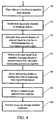
- Figure 4 is a flow chart indicating the process steps to be taken in one embodiment of the invention.
- the objects 13A, 13B, 13C ( Figures 1 and 3) to be dried and/or cleaned are placed into the chamber, and the chamber is closed.
- rinse liquid 27 is admitted into the chamber to partially or (preferably) fully submerge the objects.
- aerosol droplets of the selected liquid 37 are formed within the chamber, and a film of the selected liquid is formed and maintained on the exposed surface of the rinse liquid.
- step 97 the rinse liquid 27 and any absorbed selected liquid 37 are slowly drained from the chamber, to ultimately expose the surfaces of the objects to the aerosol droplets and to allow films of the selected liquid to form on the objects surfaces; optionally, the chamber pressure is maintained near or above the external environment pressure.
- step 99 the films of selected liquid on the objects' surfaces perform chemically squeegeeing to remove any remaining rinse liquid 27 and remaining selected liquid 37 and contaminants from the objects' surfaces.
- step 101 optionalal
- any remaining selected liquid 37 and rinse liquid 27 are removed from the chamber.
- step 103 a purge gas is passed through the chamber to remove any remaining gas and/or liquid particles from the chamber.
- the objects, now dried and/or cleaned, can be removed from the chamber or may be further processed in the chamber.
- a reservoir 121 of a substantially inert displacement gas 122 such as N 2 , CO or CO 2 , is optionally provided and is in fluid communication with the chamber 11.
- the inert gas 122 in the reservoir 121 passes through a port 123 and an associated valve and pressure control device 125 to enter the chamber 11.
- the valve and pressure control device 125 senses the increasing (negative) pressure that is created within the chamber 11 as the rinse liquid 27 is drained from the chamber using the port and valve 41 and 43.
- a chamber pressure p that is somewhat higher than the local external pressure p(external) is preferred here so that some of the inert gas 122 will tend to move out of the chamber 11 into the external environment and will discourage in-flow of gases from the external environment, if the chamber is not sufficiently air-tight.
- the pressure p maintained within the chamber 11 may be somewhat less than p(external), perhaps as low as 0.8p(external), and still discourage entry of gas from the external environment into the chamber.
- the inert gas 122 may be removed from the chamber to an inert gas reservoir 127 before the next step is taken in processing the selected objects.
- valve and pressure control device 125 need not sense the internal pressure of the chamber 11.
- the valve and pressure control device 125 admits insert gas 122 at a programmed volume flow rate r3 from the inert gas reservoir 121, where the rate r3 is sufficient to maintain the internal pressure p ⁇ p(external) or higher within the chamber 11 as the rinse liquid 27 drains from the chamber.
- the temperature T of the inert gas 122 is preferably at or near the temperature of the rinse liquid, which is usually room temperature or somewhat colder or somewhat warmer.
- the purge gas reservoir 75 may also serve as the inert gas reservoir 121, with inclusion of the valve and pressure control device 125.
Landscapes
- Engineering & Computer Science (AREA)
- Mechanical Engineering (AREA)
- General Engineering & Computer Science (AREA)
- Chemical & Material Sciences (AREA)
- Chemical Kinetics & Catalysis (AREA)
- General Chemical & Material Sciences (AREA)
- Health & Medical Sciences (AREA)
- Life Sciences & Earth Sciences (AREA)
- Molecular Biology (AREA)
- Cleaning Or Drying Semiconductors (AREA)
- Cleaning By Liquid Or Steam (AREA)
Claims (9)
- Vorrichtung (10) zum Trocknen eines Gegenstands (13A, 13B, 13C), wobei die Vorrichtung umfasst:(a) eine abgeschlossene Kammer (11) für einen zu trocknenden Gegenstand (13A, 13B, 13C), wobei die Kammer Folgendes aufweist:und(i) einen öffenbaren Zugang (15) zum Unterbringen bzw. Herausnehmen des Gegenstands (13A, 13B, 13C) in der Kammer (11) bzw. aus der Kammer (11),(ii) eine erste Öffnung (21) in Fluidkommunikation mit einer Spülflussigkeitsquelle (25) zum Zuführen einer Spülflüssigkeit (27) in die Kammer (11), um den Gegenstand (13A, 13B, 13C) teilweise oder gänzlich in der Spülflüssigkeit (27) einzutauchen,(iii) eine zweite Öffnung (41) zum Ablassen der Spülflüssigkeit (27) aus der Kammer (11);(b) einen Vibrationskopf (61) in Fluidkommunikation mit der abgeschlossenen Kammer (11) zur Bildung von Aerosoltröpfchen (39) in der abgeschlossenen Kammer (11) aus einer ausgewählten Flüssigkeit (37).
- Vorrichtung nach Anspruch 1, wobei der Vibrationskopf (61) geeignet ist, auf mindestens einer Frequenz f zu vibrieren, die im Bereich von 10 kHz ≤ f ≤ 1000 kHz liegt.
- Vorrichtung nach Anspruch 1 oder 2, wobei die Kammer (11) des weiterenumfasst.(iv) eine dritte Öffnung (31) in Fluidkommunikation mit einer Quelle (35) einer ausgewählten Flüssigkeit zum Zuführen der ausgewahlten Flüssigkeit (37) zum Vibrationskopf (61)
- Verfahren zum Trocknen eines Gegenstands (13A, 13B, 13C), wobei das Verfahren folgende Schritte umfasst:einen zu trocknenden Gegenstand (13A, 13B, 13C) in einer abgeschlossenen Kammer (11) unterbringen;eine ausreichende Menge einer Spülflüssigkeit (27) in die Kammer (11) einlassen, so dass der Gegenstand (13A, 13B, 13C) teilweise oder gänzlich in die Spülflüssigkeit (27) eingetaucht ist;eine ausgewählte Flüssigkeit (37), deren Oberflächenspannung niedriger ist als jene der Spülflüssigkeit (27), in die Kammer (11) einlassen;aus der ausgewählten Flüssigkeit (37) in der Kammer (11) Aerosoltröpfchen (39) bilden;zulassen, dass ein Teil der Aerosoltröpfchen (39) auf einer exponierten Oberfläche (29) der Spülflüssigkeit (27) einen Film (30) der ausgewählten Flüssigkeit (37) bildet;die Spülflüssigkeit (27) aus der Kammer (11) ablassen und zulassen, dass sich auf den exponierten Oberflächen (14A, 14B, 14C) des Gegenstands (13A, 13B, 13C) ein Film (16A, 16B, 16C) der ausgewählten Flüssigkeit (37) bildet; undzulassen, dass der Film (16A, 16B, 16C) der ausgewählten Flüssigkeit (37) die Spülflüssigkeit (27) auf den exponierten Oberflächen (14A, 14B, 14C) des Gegenstands (13A, 13B, 13C) verdrängt.
- Verfahren nach Anspruch 4, wobei der Schritt der Bildung der Aerosoltröpfchen (39) das Durchführen der ausgewählten Flüssigkeit (37) durch eine Vibrationsdüse (61) einschließt, die auf einer Frequenz f vibriert, die im Bereich 10 kHz ≤ f ≤ 1000 kHz liegt.
- Verfahren nach Anspruch 4 oder 5, wobei die ausgewahlte Flüssigkeit (37) eine im wesentlichen reaktionsunfähige Flüssigkeit ist, ausgewählt aus Isopropylalkohol, Ethylalkohol, Methylalkohol, Tetrahydrofuran, Aceton, Perfluorhexan, Hexan und Ether.
- Verfahren nach Anspruch 4 oder 5, wobei im wesentlichen alle Aerosoltröpfchen (39) in der Kammer (11) ohne Änderung der Phase der ausgewählten Flüssigkeit (37) gebildet werden.
- Verfahren nach Anspruch 4 oder 5, wobei die Aerosoltröpfchen (39) in der Kammer (11) mit einem Energieaufwand von weniger als 2 Joule pro Sekunde gebildet werden.
- Verfahren nach einem der Ansprüche 4 bis 8, wobei bei dem Schritt, bei dem der Film (16A, 16B, 16C) die Spülflüssigkeit (27) verdrängt, auch die kontaminierenden Partikel mit Durchmessern von mindestens 0,3 µm von den exponierten Oberflächen des Gegenstands (13A, 13B, 13C) entfernt werden.
Applications Claiming Priority (5)
| Application Number | Priority Date | Filing Date | Title |
|---|---|---|---|
| US08/616,165 US5685086A (en) | 1995-06-07 | 1996-03-14 | Method and apparatus for drying objects using aerosols |
| US616165 | 1996-03-14 | ||
| US62468996A | 1996-03-25 | 1996-03-25 | |
| US624689 | 1996-03-25 | ||
| PCT/US1997/003952 WO1997033702A1 (en) | 1996-03-14 | 1997-03-13 | Method and apparatus for drying and cleaning objects using aerosols |
Publications (3)
| Publication Number | Publication Date |
|---|---|
| EP0886548A1 EP0886548A1 (de) | 1998-12-30 |
| EP0886548A4 EP0886548A4 (de) | 2002-03-20 |
| EP0886548B1 true EP0886548B1 (de) | 2005-07-06 |
Family
ID=27087685
Family Applications (1)
| Application Number | Title | Priority Date | Filing Date |
|---|---|---|---|
| EP97916750A Expired - Lifetime EP0886548B1 (de) | 1996-03-14 | 1997-03-13 | Verfahren und vorrichtung zur trocknung und reinigung von gegenständen mittels aerosolen |
Country Status (7)
| Country | Link |
|---|---|
| EP (1) | EP0886548B1 (de) |
| JP (1) | JP3955924B2 (de) |
| KR (1) | KR100299486B1 (de) |
| CA (1) | CA2248759A1 (de) |
| DE (1) | DE69733686T2 (de) |
| IL (1) | IL126189A (de) |
| WO (1) | WO1997033702A1 (de) |
Families Citing this family (6)
| Publication number | Priority date | Publication date | Assignee | Title |
|---|---|---|---|---|
| WO1999026976A1 (en) * | 1997-11-26 | 1999-06-03 | Eli Lilly And Company | Tnf ligand family gene |
| US6270584B1 (en) * | 1997-12-03 | 2001-08-07 | Gary W. Ferrell | Apparatus for drying and cleaning objects using controlled aerosols and gases |
| TW417182B (en) * | 1998-06-02 | 2001-01-01 | Cfmt Inc | Wet processing methods for the manufacture of electronic components using liquids of varying temperature |
| JP3174038B2 (ja) * | 1999-01-18 | 2001-06-11 | 東邦化成株式会社 | 基板乾燥方法およびその装置 |
| KR100592997B1 (ko) * | 2000-01-17 | 2006-06-23 | 도호 카세이 가부시키가이샤 | 기판 건조방법 및 그 장치 |
| JP3802446B2 (ja) | 2002-05-15 | 2006-07-26 | 東邦化成株式会社 | 基板乾燥方法およびその装置 |
Family Cites Families (15)
| Publication number | Priority date | Publication date | Assignee | Title |
|---|---|---|---|---|
| JPS553607B2 (de) * | 1973-01-05 | 1980-01-25 | ||
| US4310973A (en) * | 1977-12-01 | 1982-01-19 | Phillips Petroleum Co. | Drying polymer solutions |
| US4334366A (en) * | 1980-09-24 | 1982-06-15 | Jetsonic Processes, Ltd. | Sonic energy perforated drum for rotary dryers |
| US4561192A (en) * | 1982-11-29 | 1985-12-31 | Dairyman's Cooperative Creamery Assoc. | Spray drying apparatus and method |
| DE68921757T2 (de) * | 1989-11-23 | 1995-10-26 | Cfm Technologies Inc | Verfahren zum Trocknen von Oberflächen. |
| US5054210A (en) * | 1990-02-23 | 1991-10-08 | S&K Products International, Inc. | Isopropyl alcohol vapor dryer system |
| US5000208A (en) * | 1990-06-21 | 1991-03-19 | Micron Technology, Inc. | Wafer rinser/dryer |
| US5143103A (en) * | 1991-01-04 | 1992-09-01 | International Business Machines Corporation | Apparatus for cleaning and drying workpieces |
| JP2639771B2 (ja) * | 1991-11-14 | 1997-08-13 | 大日本スクリーン製造株式会社 | 基板の洗浄・乾燥処理方法並びにその処理装置 |
| US5229171A (en) * | 1991-12-23 | 1993-07-20 | Research Triangle Institute | Apparatus and method for uniformly coating a substrate in an evacuable chamber |
| US5226242A (en) * | 1992-02-18 | 1993-07-13 | Santa Clara Plastics, Division Of Preco, Inc. | Vapor jet dryer apparatus and method |
| US5419351A (en) * | 1993-04-02 | 1995-05-30 | National Semiconductor Corporation | Final rinse/dry system for critical cleaning applications |
| JP3347814B2 (ja) * | 1993-05-17 | 2002-11-20 | 大日本スクリーン製造株式会社 | 基板の洗浄・乾燥処理方法並びにその処理装置 |
| CH688556A5 (it) * | 1993-12-09 | 1997-11-14 | Franco Carloni | Apparecchio elettrodomestico per lavare e/o asciugare utilizzante l'acqua calda dell'impianto centralizzato circolante in serpentine. |
| US5653045A (en) * | 1995-06-07 | 1997-08-05 | Ferrell; Gary W. | Method and apparatus for drying parts and microelectronic components using sonic created mist |
-
1997
- 1997-03-13 CA CA002248759A patent/CA2248759A1/en not_active Abandoned
- 1997-03-13 DE DE69733686T patent/DE69733686T2/de not_active Expired - Lifetime
- 1997-03-13 KR KR1019980707239A patent/KR100299486B1/ko not_active Expired - Fee Related
- 1997-03-13 IL IL12618997A patent/IL126189A/en not_active IP Right Cessation
- 1997-03-13 EP EP97916750A patent/EP0886548B1/de not_active Expired - Lifetime
- 1997-03-13 WO PCT/US1997/003952 patent/WO1997033702A1/en not_active Ceased
- 1997-03-13 JP JP53282997A patent/JP3955924B2/ja not_active Expired - Fee Related
Also Published As
| Publication number | Publication date |
|---|---|
| CA2248759A1 (en) | 1997-09-18 |
| IL126189A (en) | 2001-08-08 |
| IL126189A0 (en) | 1999-05-09 |
| DE69733686T2 (de) | 2006-05-04 |
| KR100299486B1 (ko) | 2001-09-06 |
| JP2000507044A (ja) | 2000-06-06 |
| EP0886548A4 (de) | 2002-03-20 |
| WO1997033702A1 (en) | 1997-09-18 |
| JP3955924B2 (ja) | 2007-08-08 |
| DE69733686D1 (de) | 2005-08-11 |
| KR19990087765A (ko) | 1999-12-27 |
| EP0886548A1 (de) | 1998-12-30 |
Similar Documents
| Publication | Publication Date | Title |
|---|---|---|
| US5964958A (en) | Methods for drying and cleaning objects using aerosols | |
| US5685086A (en) | Method and apparatus for drying objects using aerosols | |
| US5968285A (en) | Methods for drying and cleaning of objects using aerosols and inert gases | |
| US6270584B1 (en) | Apparatus for drying and cleaning objects using controlled aerosols and gases | |
| KR100452542B1 (ko) | 세정물 건조장치 및 건조방법 | |
| US5143103A (en) | Apparatus for cleaning and drying workpieces | |
| KR100397455B1 (ko) | 반도체의초미립자세정기 | |
| US6374837B2 (en) | Single semiconductor wafer processor | |
| US4015615A (en) | Fluid application system | |
| US20020033186A1 (en) | Processes and apparatus for treating electronic components | |
| KR20150088829A (ko) | 고 종횡비 반도체 디바이스 구조들에 대한 오염물 제거를 갖는 무-스틱션 건조 프로세스 | |
| US5974689A (en) | Chemical drying and cleaning system | |
| EP0886548B1 (de) | Verfahren und vorrichtung zur trocknung und reinigung von gegenständen mittels aerosolen | |
| WO2001026830A1 (en) | Improvements in drying and cleaning objects using controlled aerosols and gases | |
| JP2004235559A (ja) | 基板処理方法および基板処理装置 | |
| KR101110905B1 (ko) | 과포화된 세정 용액을 사용한 메가소닉 세정 | |
| CN1284159A (zh) | 改进的化学干燥和净化系统 | |
| KR20040008059A (ko) | 기판 세정 방법 및 이를 이용한 기판 세정 장치 | |
| WO2000007220A2 (en) | Wet processing methods for the manufacture of electronic components using ozonated process fluids | |
| JP2003045842A (ja) | 表面付着異質物質の除去方法及び除去装置 | |
| JPH0756323A (ja) | 基板洗浄装置 | |
| JP3137244B2 (ja) | 洗浄物の乾燥装置及びその乾燥方法 | |
| TWI275140B (en) | An in situ module for particle removal from solid-state surfaces | |
| US20020195130A1 (en) | Electrostatic charge-free solvent-type dryer for semiconductor wafers | |
| JP2963947B2 (ja) | ウエット洗浄装置 |
Legal Events
| Date | Code | Title | Description |
|---|---|---|---|
| PUAI | Public reference made under article 153(3) epc to a published international application that has entered the european phase |
Free format text: ORIGINAL CODE: 0009012 |
|
| 17P | Request for examination filed |
Effective date: 19981012 |
|
| AK | Designated contracting states |
Kind code of ref document: A1 Designated state(s): DE DK FR GB IE IT NL |
|
| RAP1 | Party data changed (applicant data changed or rights of an application transferred) |
Owner name: L-TEC CORPORATION |
|
| A4 | Supplementary search report drawn up and despatched |
Effective date: 20020130 |
|
| AK | Designated contracting states |
Kind code of ref document: A4 Designated state(s): DE DK FR GB IE IT NL |
|
| RAP1 | Party data changed (applicant data changed or rights of an application transferred) |
Owner name: SEZ AMERICA INC. |
|
| 17Q | First examination report despatched |
Effective date: 20040602 |
|
| GRAP | Despatch of communication of intention to grant a patent |
Free format text: ORIGINAL CODE: EPIDOSNIGR1 |
|
| GRAS | Grant fee paid |
Free format text: ORIGINAL CODE: EPIDOSNIGR3 |
|
| GRAA | (expected) grant |
Free format text: ORIGINAL CODE: 0009210 |
|
| RAP1 | Party data changed (applicant data changed or rights of an application transferred) |
Owner name: SEZ AG |
|
| AK | Designated contracting states |
Kind code of ref document: B1 Designated state(s): DE DK FR GB IE IT NL |
|
| PG25 | Lapsed in a contracting state [announced via postgrant information from national office to epo] |
Ref country code: NL Free format text: LAPSE BECAUSE OF FAILURE TO SUBMIT A TRANSLATION OF THE DESCRIPTION OR TO PAY THE FEE WITHIN THE PRESCRIBED TIME-LIMIT Effective date: 20050706 |
|
| REG | Reference to a national code |
Ref country code: GB Ref legal event code: FG4D |
|
| REG | Reference to a national code |
Ref country code: IE Ref legal event code: FG4D |
|
| REF | Corresponds to: |
Ref document number: 69733686 Country of ref document: DE Date of ref document: 20050811 Kind code of ref document: P |
|
| PG25 | Lapsed in a contracting state [announced via postgrant information from national office to epo] |
Ref country code: DK Free format text: LAPSE BECAUSE OF FAILURE TO SUBMIT A TRANSLATION OF THE DESCRIPTION OR TO PAY THE FEE WITHIN THE PRESCRIBED TIME-LIMIT Effective date: 20051006 |
|
| NLV1 | Nl: lapsed or annulled due to failure to fulfill the requirements of art. 29p and 29m of the patents act | ||
| PG25 | Lapsed in a contracting state [announced via postgrant information from national office to epo] |
Ref country code: IE Free format text: LAPSE BECAUSE OF NON-PAYMENT OF DUE FEES Effective date: 20060313 |
|
| ET | Fr: translation filed | ||
| PLBE | No opposition filed within time limit |
Free format text: ORIGINAL CODE: 0009261 |
|
| STAA | Information on the status of an ep patent application or granted ep patent |
Free format text: STATUS: NO OPPOSITION FILED WITHIN TIME LIMIT |
|
| 26N | No opposition filed |
Effective date: 20060407 |
|
| REG | Reference to a national code |
Ref country code: IE Ref legal event code: MM4A |
|
| REG | Reference to a national code |
Ref country code: FR Ref legal event code: CA |
|
| REG | Reference to a national code |
Ref country code: FR Ref legal event code: CD Ref country code: FR Ref legal event code: CA |
|
| PGFP | Annual fee paid to national office [announced via postgrant information from national office to epo] |
Ref country code: IT Payment date: 20110324 Year of fee payment: 15 |
|
| PGFP | Annual fee paid to national office [announced via postgrant information from national office to epo] |
Ref country code: GB Payment date: 20110321 Year of fee payment: 15 |
|
| PGFP | Annual fee paid to national office [announced via postgrant information from national office to epo] |
Ref country code: FR Payment date: 20120403 Year of fee payment: 16 |
|
| PGFP | Annual fee paid to national office [announced via postgrant information from national office to epo] |
Ref country code: DE Payment date: 20120323 Year of fee payment: 16 |
|
| GBPC | Gb: european patent ceased through non-payment of renewal fee |
Effective date: 20120313 |
|
| PG25 | Lapsed in a contracting state [announced via postgrant information from national office to epo] |
Ref country code: GB Free format text: LAPSE BECAUSE OF NON-PAYMENT OF DUE FEES Effective date: 20120313 |
|
| PG25 | Lapsed in a contracting state [announced via postgrant information from national office to epo] |
Ref country code: IT Free format text: LAPSE BECAUSE OF NON-PAYMENT OF DUE FEES Effective date: 20120313 |
|
| REG | Reference to a national code |
Ref country code: FR Ref legal event code: ST Effective date: 20131129 |
|
| REG | Reference to a national code |
Ref country code: DE Ref legal event code: R119 Ref document number: 69733686 Country of ref document: DE Effective date: 20131001 |
|
| PG25 | Lapsed in a contracting state [announced via postgrant information from national office to epo] |
Ref country code: FR Free format text: LAPSE BECAUSE OF NON-PAYMENT OF DUE FEES Effective date: 20130402 Ref country code: DE Free format text: LAPSE BECAUSE OF NON-PAYMENT OF DUE FEES Effective date: 20131001 |