EP0886611B1 - Kappe für behälter mit aufhängevorrichtung für die kappe auf einer tragstange - Google Patents
Kappe für behälter mit aufhängevorrichtung für die kappe auf einer tragstange Download PDFInfo
- Publication number
- EP0886611B1 EP0886611B1 EP97908326A EP97908326A EP0886611B1 EP 0886611 B1 EP0886611 B1 EP 0886611B1 EP 97908326 A EP97908326 A EP 97908326A EP 97908326 A EP97908326 A EP 97908326A EP 0886611 B1 EP0886611 B1 EP 0886611B1
- Authority
- EP
- European Patent Office
- Prior art keywords
- skirt
- container
- cap
- tongue
- cover
- Prior art date
- Legal status (The legal status is an assumption and is not a legal conclusion. Google has not performed a legal analysis and makes no representation as to the accuracy of the status listed.)
- Expired - Lifetime
Links
- 239000000725 suspension Substances 0.000 claims description 21
- 241001062330 Psilocybe semilanceata Species 0.000 claims 1
- 239000011324 bead Substances 0.000 description 9
- 241001272720 Medialuna californiensis Species 0.000 description 6
- 238000004519 manufacturing process Methods 0.000 description 5
- 239000004033 plastic Substances 0.000 description 4
- 238000003860 storage Methods 0.000 description 4
- 206010011655 Cushingoid Diseases 0.000 description 3
- 230000006978 adaptation Effects 0.000 description 3
- 238000004806 packaging method and process Methods 0.000 description 3
- 239000000443 aerosol Substances 0.000 description 2
- 238000004891 communication Methods 0.000 description 2
- 230000006866 deterioration Effects 0.000 description 2
- 239000012530 fluid Substances 0.000 description 2
- 239000007921 spray Substances 0.000 description 2
- 238000013519 translation Methods 0.000 description 2
- 239000004743 Polypropylene Substances 0.000 description 1
- 240000008042 Zea mays Species 0.000 description 1
- 230000000295 complement effect Effects 0.000 description 1
- 238000013461 design Methods 0.000 description 1
- 238000011161 development Methods 0.000 description 1
- 238000009826 distribution Methods 0.000 description 1
- PCHJSUWPFVWCPO-UHFFFAOYSA-N gold Chemical compound [Au] PCHJSUWPFVWCPO-UHFFFAOYSA-N 0.000 description 1
- 239000010931 gold Substances 0.000 description 1
- 229910052737 gold Inorganic materials 0.000 description 1
- 238000009434 installation Methods 0.000 description 1
- 239000007788 liquid Substances 0.000 description 1
- 230000005415 magnetization Effects 0.000 description 1
- 239000000463 material Substances 0.000 description 1
- 238000000465 moulding Methods 0.000 description 1
- 235000011837 pasties Nutrition 0.000 description 1
- 230000002093 peripheral effect Effects 0.000 description 1
- -1 polypropylene Polymers 0.000 description 1
- 229920001155 polypropylene Polymers 0.000 description 1
Images



Classifications
-
- B—PERFORMING OPERATIONS; TRANSPORTING
- B65—CONVEYING; PACKING; STORING; HANDLING THIN OR FILAMENTARY MATERIAL
- B65D—CONTAINERS FOR STORAGE OR TRANSPORT OF ARTICLES OR MATERIALS, e.g. BAGS, BARRELS, BOTTLES, BOXES, CANS, CARTONS, CRATES, DRUMS, JARS, TANKS, HOPPERS, FORWARDING CONTAINERS; ACCESSORIES, CLOSURES, OR FITTINGS THEREFOR; PACKAGING ELEMENTS; PACKAGES
- B65D83/00—Containers or packages with special means for dispensing contents
- B65D83/14—Containers for dispensing liquid or semi-liquid contents by internal gaseous pressure, i.e. aerosol containers comprising propellant
- B65D83/40—Closure caps
-
- B—PERFORMING OPERATIONS; TRANSPORTING
- B65—CONVEYING; PACKING; STORING; HANDLING THIN OR FILAMENTARY MATERIAL
- B65D—CONTAINERS FOR STORAGE OR TRANSPORT OF ARTICLES OR MATERIALS, e.g. BAGS, BARRELS, BOTTLES, BOXES, CANS, CARTONS, CRATES, DRUMS, JARS, TANKS, HOPPERS, FORWARDING CONTAINERS; ACCESSORIES, CLOSURES, OR FITTINGS THEREFOR; PACKAGING ELEMENTS; PACKAGES
- B65D51/00—Closures not otherwise provided for
- B65D51/24—Closures not otherwise provided for combined or co-operating with auxiliary devices for non-closing purposes
- B65D51/242—Closures not otherwise provided for combined or co-operating with auxiliary devices for non-closing purposes provided with means for facilitating lifting or suspending of the container
Definitions
- the present invention relates to a cover for a container, which once adapted on the container allows it to be hung on a display pin. She finds more particularly, but not exclusively, its application for presentation for sale on display pins of container gaseous, liquid or pasty products, possibly under pressure, which are provided with a spray head and commonly known as "bombs aerosols >>, ⁇ atomizers >> or ⁇ sprayers >>, the cover allowing both protect the spray head and hang the container to a display pin.
- a container cover of the aforementioned type has an open skirt at its base to allow adaptation of the cover on the container, and a upper transverse wall for closing the cover.
- a tongue on the upper transverse wall of the cover is transferred to the suspension tab: the cover remains intact.
- the tabs prevent the containers from overlapping, by view of their storage.
- plastic packaging commonly known as ⁇ blisters>>. These packages are molded according to the shape of the container and allow to wrap it entirely. They also have a surface tab plane in which an opening for the passage of the spindle is practiced.
- the object of the invention is to provide a cover for the suspension a container on a display pin, which has all the advantages covers of the third and fourth solutions mentioned above without present the disadvantages inherent in each of these solutions, that is to say mainly a hood which allows a stable and reliable suspension of the container, which allows a user to easily hang or unhook the container of a display pin, which is capable of being threaded on a spindle whatever the shape and size in height of the end of the spindle, which allows to keep a reduced spacing between the display pins substantially identical to that obtained with the third variant, which makes it possible to put the covers on the containers on usual automated assembly lines, which allows incidentally the stacking of the containers.
- the cover according to the invention is known from US-A-4,258,857 in that it includes a skirt with an inner side open for its adaptation on a container, and a substantially flat upper face having diametrically opposite bearing portions with respect to the central axis of the skirt, and hooking means for the suspension of the cover on a spindle which, below the plane of the upper face of the skirt, at least two support points spaced apart for the spindle.
- the means hooks are in the form of a hook integrated in the volume delimited by the skirt, and a slender passage is provided in the cover for inserting the spindle through the upper face of the skirt and for guide to the hook.
- the cover 1 comprises a cylindrical skirt 2 with a central axis 2 a , consisting of a cylindrical side wall 2 b whose lower face 2 c is open so as to allow mounting of the cover on the upper part of a container A and the upper face 2 d of which can be closed, as the case may be (variant of FIGS. 1 to 5) or open (variant of FIG. 6).
- the cover 1 is fixed on the upper part of the container A by any suitable means known to those skilled in the art, and for example by clip the lower edge of skirt 2 onto the top of the container.
- the container A and the skirt 2 of the cover may be designed to so that the cover is screwed onto the upper part of the container A.
- the shape of the container and therefore the shape of the skirt which is adapted to that of the container, is cylindrical, which corresponds to the most common form in the field containers such as aerosol cans, atomizers or sprayers.
- the invention is however not limited to this particular form of container but may find its application to any known form of container.
- the skirt 2 of the cover 1 may for its adaptation on a container, have any polygonal shape in section, or have a sectional shape that is oval.
- the cover 1 comprises, in its upper part 4, for its suspension on a display spindle, a hook which is integrated in the volume delimited by the skirt 2, that is to say ie a hook which does not protrude with respect to the outer face of the side wall 2 b of the skirt, or with respect to the lower 2 c and upper 2 d faces of the skirt 2.
- the upper part 4 of the cover will be called attachment head.
- the cover 1 has a slender passage which makes it possible to introduce the display spindle through the upper face 2 d of the skirt, and whose function is to guide the spindle relative to the cover up to the hook.
- the design of the hook and the elongate passage is different for each variant, and will now be detailed for each variant.
- the upper face 2 d of the skirt 2 is closed by an end wall 5 a substantially planar and transverse to the axis 2 a .
- the channel 6 has a diameter equal to or slightly greater than the diameter of the display pins, that is to say varies between 5 mm and 2 cm and preferably between 8 mm and 1 cm.
- a vertical groove 9 with a longitudinal axis 9 parallel to and offset from the axis 7 of suspension is formed in the gripping head 4.
- the bottom 10 of the groove 9 arrives at the horizontal plane tangential to the channel 6 cylindrical.
- a substantially horizontal groove 11, the bottom of which consists of a lower transverse wall 5b, is formed in the cover so as to bring the vertical groove 9 and the channel 6 into communication.
- a longitudinal passage is provided for the spindle, from the upper end wall 5 a to the channel 6 passing successively through the grooves 9 then 11. All of the grooves 9 and 11 and of the channel 6 present, in side view, a general L-shaped profile.
- the vertical 9 and horizontal 11 grooves form the elongated passage allowing the spindle to access and be guided to the channel 6.
- the width l of these two grooves will be substantially identical and at least equal to the diameter of the pins display standards.
- the wall 5 a at the level of the channel 6 forms a suspension hook 8 integrated into the attachment head 4, and comprising a bearing surface 8 a capable of cooperating with the spindle, and of length equal to the diameter of the skirt 2.
- the suspension hook 8 is located in the vertical plane of symmetry of the skirt 2, which makes it possible to maintain the longitudinal axis of the cylindrical container A in a vertical plane, when this container is suspended from a spindle display stand, via its cover 1.
- the suspension of a container fitted with its cover 1 on a display spindle is carried out as follows.
- the container covered with its cover is presented with respect to the spindle so that the inlet of the groove 9 is aligned and perpendicular to the spindle; introducing and sliding the pin into the groove 9 by lifting the container until the display pin comes into contact with the bottom 10 of the groove 9; the container is moved laterally so as to slide the spindle in the horizontal groove 11, until the spindle enters the channel 6; then made slightly down the container, so as to bring the supporting surface 8 a into contact with the pin.
- To unhook a container from a display pin simply perform the above operations in reverse.
- the passage elongated formed by the grooves 9 and 11 advantageously allows the hood to be easily and quickly suspended or lifted from a point any spindle, without having to slide the cover by the free end of the spindle.
- the upper end wall 5 a of the cover of FIG. 1 has a planar contour having support portions diametrically opposite with respect to the central axis of the skirt 2; this is mainly the portion referenced 12 a , and the support portion 12 b which has been hatched in FIG. 1.
- These two diametrically opposite support portions 12 a , 12 b advantageously make it possible to mount automatically the cover on a container, using a jack, the rod of which is provided at its free end with a pressure surface capable of being applied at least on the two support portions 12 a , 12 b of the upper face 2 d of the cover.
- the cover does not include these two diametrically opposite support portions, such an automatic mounting operation would not be possible, because the cover would be unbalanced during its mounting, under the action of the pressure of the jack. .
- the diametrically opposite bearing portions of the upper face 2 d can advantageously serve as portions support for the bottom of a container, and thereby advantageously make it possible to stack the containers fitted with their covers one above the other for storage.
- a circular light 13 with a central vertical axis is produced in the attachment head 4, and more precisely in the wall 5 b , so as to place the interior of the lower part 3 of the skirt in communication with the cylindrical channel 6. It saves on material and makes the hood lighter.
- the lower part 3 of the skirt 2 is provided with a bead 14 annular projecting with respect to the internal surface of the skirt 2 and likely to bear on the corresponding bead of the container.
- the bead 14 has, for example, a height of about 0.2 mm and a thickness of about 1 mm.
- the bead 14 is reinforced by triangular lugs 15, one of which one side is attached to the skirt 2 and the other to the bead 14.
- the pins 15 are distributed homogeneously along the bead 14: they are likely to have different and varied provisions. They present, for example, a height of 2mm and a width of 0.8mm.
- Projections 16, of oblong shape can be provided below of the bead 14 and distributed uniformly or differently along the internal circumference of skirt 2. They are intended to also rely on corresponding means on the container to strengthen the attachment of the cover thereon. They present, by example, a thickness of about 0.5mm.
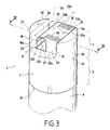
- the cover 1 comprises a central part 17 whose profile in section in a vertical plane has a U-shape.
- the central part 17 consists of two vertical walls 18,19, and of a bottom 20, connected by rounded surfaces.
- Each vertical wall 18, 19 defines with the cylindrical wall 2 b of the skirt 2 and the upper end wall 5 a , two blocks respectively 21, 22, diametrically opposite with respect to the central axis 2 a of the skirt 2, and having in section along a horizontal plane, a half-moon shape.
- the upper half-moon faces of the two blocks 21, 22 form two diametrically opposite support portions, which are comparable to the support portions 12 a and 12 b of the variant of FIGS. 1 and 2, and bring the same advantages previously. described.
- a tongue 23 is provided to form an integrated suspension hook of small thickness e , comparable in practice to the thickness of the side wall 2 b of the cylindrical skirt 2.
- This tongue extends from the block 22, and in the example illustrated from the rectilinear edge 22 a of the upper half-moon face of the block 22.
- the tongue 23 has a wave-shaped profile (FIG. 4), with from the block 22 a first curved portion 23 a oriented towards the bottom 20, and a second curved portion 23 b in an arc of an upwardly oriented circle, coming substantially to tangent to the plane of the upper half-moon faces of the two blocks 21 and 22.
- the underside 23 c of the second portion 23 b is intended to serve as a bearing surface for a display pin B ( Figure 4). According to another alternative embodiment of the invention, this bearing surface 23 c could be hollowed out in places to form parallel surface fingers of identical shape capable of fulfilling the same function.
- the wave shape of the tongue 23 advantageously makes it possible to give it better rigidity.
- the latter is preferably connected to the vertical wall 19 of the block 22 by two vertical sides 24, 25, oriented transversely to the plane 19.
- ribs 26 for supporting the tongue 22 are more particularly produced in the first curved portion 23 a .
- the internal face 18 a of the vertical wall 18, and the bottom 20 of the U-shaped central part 17 delimit with the free edge 23 d of the tongue 22 a long passage in the form of L, for display pin B.
- a light 27 is made in the bottom 20 of the central part 17 in the shape of a U.
- This light 27 brings the same advantages previously described for light 13 of the variant of Figures 1 and 2.
- this light 27 has a rectangular surface which corresponds substantially to the projection of the tongue 23 on the bottom 20, which advantageously reduces the costs of molding tools.
- the light 27 allows the molds upper and lower to be joined, and allows comparatively by example in the variant of Figure 1 to avoid to achieve the hook suspension to use a drawer which increases the cost of the mold.
- the length L of the tongue 23 taken in the direction of its suspension axis 23 e is less than the diameter D of the skirt 2, and the bottom 20 of the central part 17 has two portions 20 a and 20 b connecting the two walls 18 and 19 of the two blocks 21, 22 on either side of the tongue 23.
- These two portions 20 a and 20 b allow, despite the presence of the light 27, to keep the skirt 2 of the cover very good rigidity in a direction transverse to the suspension axis 23 e .
- the rigidity of the skirt in a direction parallel to the suspension axis 23 c is in turn imparted by the two blocks 21, 22 in a half-moon shape.
- projections 28 comparable to projections 16 of the variant of FIG. 2 are created inside the skirt 2.
- Vertical threads 29 extend from the bottom 20 of the central part 17 to the lower end of the skirt, slightly above the projections 28. These threads make it possible to reinforce the structure of the skirt 2 in its lower part 3, and also to fix the cover 1 on a container provided with a bead in its upper part, the lower end of the threads 29 forming a stop for the bead of the container.
- the cover 1 consists of a cylindrical skirt 2 whose upper face 2 d is fully open.
- the cover 2 were made two diametrically opposite openings 30 and two notches 31 in an L shape.
- Each notch 31 extends from the upper edge of the skirt 2 to one of the two openings 30 .
- the two diametrically aligned apertures 30 provide two support points spaced 30 has the pin, and fulfill the same function as the channel 6 of the embodiment of figures 1 and 2.
- the two notches 31 L define an elongated passage for the introduction of the spindle to the two support portions 30 a from the upper face 2 d of the skirt, and thus fulfill the same function as the grooves 9 and 11.
- the open upper face 2 d of the skirt 2 is reduced to the upper edge of the skirt, which forms a plane contour transverse to the central axis 2 a of the skirt.
- This planar outline has, as for the variants of FIGS. 1 to 5, diametrically opposite bearing portions 32 a and 32 b fulfilling the same function and providing the same advantages as the portions 12 a and 12 b of the variant of FIGS. 1 and 2 , or else that the upper bearing faces of the blocks 21, 22 in the form of a half-moon of the variant of FIGS. 3 to 5.
- the cover in the form of embodiment of Figure 6 is more particularly suitable for hanging on a display spindle a container already closed by a cap.
- the cap has a simple shape: for example it consists of a skirt cylindrical with one end open and the other closed with a flat wall, the open end comprising means for fixing to the container.
- the cover is removably attached to the cover by any known means, for example by magnetization. the user can, by example, unhook the cover-cap-container assembly from the display spindle, then return the cover to the cash register at the exit of the store to avoid keep only the container with its cap.
- the cover is permanently fixed to the display spindle, and the user grasps the entire container that is to say with the closing cap, the cap remaining fixed to the spindle of display.
- the cover 1 of FIG. 6 could be closed by means of a transverse wall provided below the level of the openings 30.
- the cover acts as both the closure cap of the upper part of the container, and means for suspending the container to a display pin.
- the covers of the invention will preferably be one-piece parts molded, of plastic, and in particular of polypropylene.
Landscapes
- Engineering & Computer Science (AREA)
- Mechanical Engineering (AREA)
- Chemical & Material Sciences (AREA)
- Dispersion Chemistry (AREA)
- Closures For Containers (AREA)
- Load-Engaging Elements For Cranes (AREA)
- Automatic Analysis And Handling Materials Therefor (AREA)
- Packaging Of Annular Or Rod-Shaped Articles, Wearing Apparel, Cassettes, Or The Like (AREA)
- Table Equipment (AREA)
- Supports Or Holders For Household Use (AREA)
- Sealing Of Jars (AREA)
- Supplying Of Containers To The Packaging Station (AREA)
- Details Of Rigid Or Semi-Rigid Containers (AREA)
Claims (11)
- Kappe für einen Behälter, die einen Mantel (2) mit einer offenen Unterseite (2c) zum Aufsetzen auf einen Behälter und einer im wesentlichen ebenen Oberseite (2d) aufweist, welche in Bezug auf die zentrale Achse (2a) des Mantels diametral entgegengesetzt liegenden Auflageabschnitte und Befestigungsmittel zum Aufhängen der Kappe an einer Tragestange besitzt, die diesseits der Ebene der Oberseite des Mantels mindestens zwei beabstandete Auflagepunkte für die Tragestange aufweisen, dadurch gekennzeichnet, daß die Befestigungsmittel die Form eines in das vom Mantel (2) begrenzte Volumen eingearbeiteten Hakens haben und daß in Längsrichtung ein Durchlaß in der Kappe vorgesehen ist, um die Tragestange durch die Oberseite (2c) des Mantels einzuschieben und sie bis zum Haken zu führen.
- Kappe nach Anspruch 1, dadurch gekennzeichnet, daß der Durchlaß in Längsrichtung ein im wesentlichen L-förmiges Profil aufweist.
- Kappe nach Anspruch 1 oder 2, dadurch gekennzeichnet, daß der Durchlaß in Längsrichtung eine im wesentlichen konstante Breite l aufweist.
- Kappe nach einem der Ansprüche 1 bis 3, dadurch gekennzeichnet, daß sie eine untere Querwand (5b) unter dem Haken aufweist, daß der Haken eine Auflagefläche (8a, 23c) für eine Tragestange besitzt, und daß in der unteren Wand (5b) unter der Auflagefläche (8a, 23c) eine Öffnung (13; 27) angebracht ist.
- Kappe nach Anspruch 4, dadurch gekennzeichnet, daß der Haken von einer Zunge (23) gebildet wird und daß die Öffnung (27) im wesentlichen dem Vorstehen der Zunge (23) auf die untere Wand (5b) entspricht.
- Kappe nach Anspruch 5, dadurch gekennzeichnet, daß die Länge (L) der Zunge (23) kleiner ist als der Durchmesser (D) der Kappe und daß die untere Wand (5b) der Kappe zu beiden Seiten der Zunge zwei Abschnitte (20a, 20b) zur Versteifung des Mantels (2) aufweist.
- Kappe nach einem der Ansprüche 2 bis 6, dadurch gekennzeichnet, daß sie zwei Blöcke (21, 22) aufweist, die mit einer unteren Wand (5b) einen zentralen, U-förmigen Bereich (17) definieren, daß die Zunge (23) sich im zentralen Bereich (17) von einem ersten (22) der beiden Blöcke ausgehend erstreckt, und daß der freie Rand (23d) der Zunge (23) mit der Innenwand (18) des zweiten Blocks (21) und der unteren Wand (5b) einen in Längsrichtung verlaufenden, im wesentlichen L-förmigen Durchlaß für einen Tragestange bildet.
- Kappe nach Anspruch 7, dadurch gekennzeichnet, daß die Zunge (23), die eine geringe Dicke (e) aufweist, zu ihrer Versteifung mit der Innenwand (19) des ersten Blocks (22) durch mindestens zwei senkrechte Flanken (24, 25) verbunden ist.
- Kappe nach Anspruch 8, dadurch gekennzeichnet, daß die Zunge (23) ein gewelltes Profil mit einem ersten gekrümmten Bereich (23a), der vom ersten Block (22) zum Boden des zentralen Bereichs (17) hin gerichtet ist, und einem zweiten gekrümmten Bereich (23b) aufweist, der zur Oberseite (2d) des Mantels (2) hin ausgerichtet ist.
- Behälter, der zum Zweck seiner Aufhängung an einer Verkaufsständer-Tragestange mit einer Kappe nach einem beliebigen der Ansprüche 1 bis 9 ausgestattet ist.
- Behälter mit einer Verschlußkappe, dadurch gekennzeichnet, daß er zum Zweck seiner Aufhängung lösbar an einer Kappe gemäß einem beliebigen der Ansprüche 1 bis 9 befestigt ist.
Applications Claiming Priority (3)
| Application Number | Priority Date | Filing Date | Title |
|---|---|---|---|
| FR9603016 | 1996-03-11 | ||
| FR9603016A FR2745800B1 (fr) | 1996-03-11 | 1996-03-11 | Capot de fermeture pour recipients |
| PCT/FR1997/000414 WO1997033814A1 (fr) | 1996-03-11 | 1997-03-10 | Capot pour recipient comprenant des moyens de suspension du capot sur une broche |
Publications (2)
| Publication Number | Publication Date |
|---|---|
| EP0886611A1 EP0886611A1 (de) | 1998-12-30 |
| EP0886611B1 true EP0886611B1 (de) | 1999-08-18 |
Family
ID=9490046
Family Applications (1)
| Application Number | Title | Priority Date | Filing Date |
|---|---|---|---|
| EP97908326A Expired - Lifetime EP0886611B1 (de) | 1996-03-11 | 1997-03-10 | Kappe für behälter mit aufhängevorrichtung für die kappe auf einer tragstange |
Country Status (11)
| Country | Link |
|---|---|
| EP (1) | EP0886611B1 (de) |
| CN (1) | CN1213351A (de) |
| AT (1) | ATE183472T1 (de) |
| AU (1) | AU2031797A (de) |
| BR (1) | BR9707968A (de) |
| DE (1) | DE69700434T2 (de) |
| ES (1) | ES2138447T3 (de) |
| FR (1) | FR2745800B1 (de) |
| PL (1) | PL328702A1 (de) |
| TW (1) | TW333514B (de) |
| WO (1) | WO1997033814A1 (de) |
Families Citing this family (2)
| Publication number | Priority date | Publication date | Assignee | Title |
|---|---|---|---|---|
| US7086545B2 (en) | 2002-01-16 | 2006-08-08 | Ajava Pinata, L.L.C. | Suspended containers |
| US9844301B2 (en) * | 2013-11-25 | 2017-12-19 | Henry Penny Corporation | Cover for holding tray |
Family Cites Families (4)
| Publication number | Priority date | Publication date | Assignee | Title |
|---|---|---|---|---|
| US4258857A (en) * | 1978-08-16 | 1981-03-31 | Grow Group, Inc. | Display cap |
| DE8714791U1 (de) * | 1987-11-06 | 1989-03-09 | Weener Plastik Gmbh & Co Kg, 2952 Weener | Vorrichtung für Flaschen o. dgl. |
| DE9108514U1 (de) * | 1991-07-10 | 1992-01-09 | Schreiber, Klaus, 2000 Hamburg | Haltevorrichtung |
| US5373953A (en) * | 1994-02-17 | 1994-12-20 | Fenton; Russell R. | Display mounting cap for containers |
-
1996
- 1996-03-11 FR FR9603016A patent/FR2745800B1/fr not_active Expired - Fee Related
-
1997
- 1997-03-10 CN CN97192987.4A patent/CN1213351A/zh active Pending
- 1997-03-10 ES ES97908326T patent/ES2138447T3/es not_active Expired - Lifetime
- 1997-03-10 EP EP97908326A patent/EP0886611B1/de not_active Expired - Lifetime
- 1997-03-10 DE DE69700434T patent/DE69700434T2/de not_active Expired - Fee Related
- 1997-03-10 PL PL97328702A patent/PL328702A1/xx unknown
- 1997-03-10 BR BR9707968-5A patent/BR9707968A/pt not_active Application Discontinuation
- 1997-03-10 AT AT97908326T patent/ATE183472T1/de active
- 1997-03-10 WO PCT/FR1997/000414 patent/WO1997033814A1/fr not_active Ceased
- 1997-03-10 AU AU20317/97A patent/AU2031797A/en not_active Abandoned
- 1997-03-10 TW TW086102951A patent/TW333514B/zh active
Also Published As
| Publication number | Publication date |
|---|---|
| CN1213351A (zh) | 1999-04-07 |
| ES2138447T3 (es) | 2000-01-01 |
| FR2745800B1 (fr) | 1998-04-17 |
| WO1997033814A1 (fr) | 1997-09-18 |
| AU2031797A (en) | 1997-10-01 |
| PL328702A1 (en) | 1999-02-15 |
| EP0886611A1 (de) | 1998-12-30 |
| BR9707968A (pt) | 2000-01-04 |
| DE69700434D1 (de) | 1999-09-23 |
| FR2745800A1 (fr) | 1997-09-12 |
| DE69700434T2 (de) | 2000-02-24 |
| ATE183472T1 (de) | 1999-09-15 |
| TW333514B (en) | 1998-06-11 |
Similar Documents
| Publication | Publication Date | Title |
|---|---|---|
| EP0641720B1 (de) | An einer Flasche befestigbarer Behälter für Dosierzusatzteile | |
| EP2374727B1 (de) | Lebensmittelverpackung mit Deckel, und Verschlusssystem für eine Verpackung | |
| BE1005930A3 (fr) | Necesaire pour boite a casse-croute. | |
| FR2819496A1 (fr) | Emballage pour produits alimentaires, et notamment pour fromages | |
| LU88845A1 (fr) | Conditionnement pour produits liquides et en particulier pour produits alimentaires | |
| EP0886611A1 (de) | Kappe für behälter mit aufhängevorrichtung für die kappe auf einer tragstange | |
| FR2588532A1 (fr) | Distributeurs de pates alimentaires. | |
| EP0568452A1 (de) | Faltbarer Schuhaufhänger | |
| FR2764179A1 (fr) | Dispositif permettant le retrait d'objets se trouvant dans un bocal | |
| EP1363843A1 (de) | Spender mit einem flexiblen beutel und verfahren zu dessen herstellung | |
| EP1441584A1 (de) | Kasten zum stauen und/oder zum fertigmachen von langleinen | |
| EP1869381B1 (de) | Vorrichtung zur aufbewahrung von flaschen in einem kühlschrank | |
| EP0052596A2 (de) | Aufhängeverpackung, Verpackungsverfahren und Einrichtung zur Durchführung dieses Verfahrens | |
| FR2737189A1 (fr) | Boite avec languette de suspension | |
| FR2693885A1 (fr) | Porte-pinceaux. | |
| FR2695114A1 (fr) | Distributeur de papier en rouleau. | |
| EP1593611B1 (de) | Verpackung aus Kunststoff für die Butter | |
| EP1092651A1 (de) | Verpackung für das Konditionieren und die Präsentation von Artikelgruppen | |
| FR2983459A1 (fr) | Dispositif de maintien de pots contenant un produit alimentaire d'un appareil de refrigeration | |
| FR2723566A3 (fr) | Bouteille en matiere plastique | |
| FR3133530A1 (fr) | Récipient pour la conservation dans du liquide de végétaux | |
| FR2925468A1 (fr) | Emballage avec un dispositif d'accrochage d'un ustensible doseur | |
| FR2914546A1 (fr) | Dispositif pour la fixation d'un objet au moins partiellement plat sur la paroi d'un recipient. | |
| FR2658798A1 (fr) | Dispositif pour l'emballage d'une plante en pot. | |
| CH423617A (fr) | Berceau support pour le conditionnement en série d'ampoules, bouteilles ou autres articles à corps allongé |
Legal Events
| Date | Code | Title | Description |
|---|---|---|---|
| PUAI | Public reference made under article 153(3) epc to a published international application that has entered the european phase |
Free format text: ORIGINAL CODE: 0009012 |
|
| 17P | Request for examination filed |
Effective date: 19980826 |
|
| AK | Designated contracting states |
Kind code of ref document: A1 Designated state(s): AT BE CH DE DK ES FR GB IT LI NL PT SE |
|
| GRAG | Despatch of communication of intention to grant |
Free format text: ORIGINAL CODE: EPIDOS AGRA |
|
| GRAG | Despatch of communication of intention to grant |
Free format text: ORIGINAL CODE: EPIDOS AGRA |
|
| GRAH | Despatch of communication of intention to grant a patent |
Free format text: ORIGINAL CODE: EPIDOS IGRA |
|
| 17Q | First examination report despatched |
Effective date: 19990108 |
|
| GRAH | Despatch of communication of intention to grant a patent |
Free format text: ORIGINAL CODE: EPIDOS IGRA |
|
| GRAA | (expected) grant |
Free format text: ORIGINAL CODE: 0009210 |
|
| AK | Designated contracting states |
Kind code of ref document: B1 Designated state(s): AT BE CH DE DK ES FR GB IT LI NL PT SE |
|
| PG25 | Lapsed in a contracting state [announced via postgrant information from national office to epo] |
Ref country code: SE Free format text: THE PATENT HAS BEEN ANNULLED BY A DECISION OF A NATIONAL AUTHORITY Effective date: 19990818 Ref country code: AT Free format text: LAPSE BECAUSE OF FAILURE TO SUBMIT A TRANSLATION OF THE DESCRIPTION OR TO PAY THE FEE WITHIN THE PRESCRIBED TIME-LIMIT Effective date: 19990818 |
|
| REF | Corresponds to: |
Ref document number: 183472 Country of ref document: AT Date of ref document: 19990915 Kind code of ref document: T |
|
| REG | Reference to a national code |
Ref country code: CH Ref legal event code: EP |
|
| REF | Corresponds to: |
Ref document number: 69700434 Country of ref document: DE Date of ref document: 19990923 |
|
| ITF | It: translation for a ep patent filed | ||
| GBT | Gb: translation of ep patent filed (gb section 77(6)(a)/1977) |
Effective date: 19991109 |
|
| REG | Reference to a national code |
Ref country code: ES Ref legal event code: FG2A Ref document number: 2138447 Country of ref document: ES Kind code of ref document: T3 |
|
| REG | Reference to a national code |
Ref country code: PT Ref legal event code: SC4A Free format text: AVAILABILITY OF NATIONAL TRANSLATION Effective date: 19991116 |
|
| REG | Reference to a national code |
Ref country code: DK Ref legal event code: T3 |
|
| PLBE | No opposition filed within time limit |
Free format text: ORIGINAL CODE: 0009261 |
|
| STAA | Information on the status of an ep patent application or granted ep patent |
Free format text: STATUS: NO OPPOSITION FILED WITHIN TIME LIMIT |
|
| 26N | No opposition filed | ||
| PG25 | Lapsed in a contracting state [announced via postgrant information from national office to epo] |
Ref country code: LI Free format text: LAPSE BECAUSE OF NON-PAYMENT OF DUE FEES Effective date: 20010331 Ref country code: CH Free format text: LAPSE BECAUSE OF NON-PAYMENT OF DUE FEES Effective date: 20010331 |
|
| REG | Reference to a national code |
Ref country code: CH Ref legal event code: PL |
|
| REG | Reference to a national code |
Ref country code: GB Ref legal event code: IF02 |
|
| PGFP | Annual fee paid to national office [announced via postgrant information from national office to epo] |
Ref country code: NL Payment date: 20020822 Year of fee payment: 6 |
|
| PGFP | Annual fee paid to national office [announced via postgrant information from national office to epo] |
Ref country code: GB Payment date: 20020823 Year of fee payment: 6 |
|
| PGFP | Annual fee paid to national office [announced via postgrant information from national office to epo] |
Ref country code: DE Payment date: 20020827 Year of fee payment: 6 |
|
| PGFP | Annual fee paid to national office [announced via postgrant information from national office to epo] |
Ref country code: FR Payment date: 20020828 Year of fee payment: 6 Ref country code: DK Payment date: 20020828 Year of fee payment: 6 |
|
| PGFP | Annual fee paid to national office [announced via postgrant information from national office to epo] |
Ref country code: PT Payment date: 20020829 Year of fee payment: 6 Ref country code: ES Payment date: 20020829 Year of fee payment: 6 |
|
| PGFP | Annual fee paid to national office [announced via postgrant information from national office to epo] |
Ref country code: BE Payment date: 20020913 Year of fee payment: 6 |
|
| PG25 | Lapsed in a contracting state [announced via postgrant information from national office to epo] |
Ref country code: GB Free format text: LAPSE BECAUSE OF NON-PAYMENT OF DUE FEES Effective date: 20030310 |
|
| PG25 | Lapsed in a contracting state [announced via postgrant information from national office to epo] |
Ref country code: ES Free format text: LAPSE BECAUSE OF NON-PAYMENT OF DUE FEES Effective date: 20030311 |
|
| PG25 | Lapsed in a contracting state [announced via postgrant information from national office to epo] |
Ref country code: DK Free format text: LAPSE BECAUSE OF NON-PAYMENT OF DUE FEES Effective date: 20030331 Ref country code: BE Free format text: LAPSE BECAUSE OF NON-PAYMENT OF DUE FEES Effective date: 20030331 |
|
| BERE | Be: lapsed |
Owner name: S.A. *DECATHLON Effective date: 20030331 |
|
| PG25 | Lapsed in a contracting state [announced via postgrant information from national office to epo] |
Ref country code: PT Free format text: LAPSE BECAUSE OF NON-PAYMENT OF DUE FEES Effective date: 20030930 |
|
| PG25 | Lapsed in a contracting state [announced via postgrant information from national office to epo] |
Ref country code: NL Free format text: LAPSE BECAUSE OF NON-PAYMENT OF DUE FEES Effective date: 20031001 Ref country code: DE Free format text: LAPSE BECAUSE OF NON-PAYMENT OF DUE FEES Effective date: 20031001 |
|
| GBPC | Gb: european patent ceased through non-payment of renewal fee |
Effective date: 20030310 |
|
| REG | Reference to a national code |
Ref country code: DK Ref legal event code: EBP |
|
| NLV4 | Nl: lapsed or anulled due to non-payment of the annual fee |
Effective date: 20031001 |
|
| REG | Reference to a national code |
Ref country code: PT Ref legal event code: MM4A Free format text: LAPSE DUE TO NON-PAYMENT OF FEES Effective date: 20030930 |
|
| REG | Reference to a national code |
Ref country code: ES Ref legal event code: FD2A Effective date: 20030311 |
|
| PG25 | Lapsed in a contracting state [announced via postgrant information from national office to epo] |
Ref country code: FR Free format text: LAPSE BECAUSE OF NON-PAYMENT OF DUE FEES Effective date: 20041130 |
|
| REG | Reference to a national code |
Ref country code: FR Ref legal event code: ST |
|
| PG25 | Lapsed in a contracting state [announced via postgrant information from national office to epo] |
Ref country code: IT Free format text: LAPSE BECAUSE OF NON-PAYMENT OF DUE FEES;WARNING: LAPSES OF ITALIAN PATENTS WITH EFFECTIVE DATE BEFORE 2007 MAY HAVE OCCURRED AT ANY TIME BEFORE 2007. THE CORRECT EFFECTIVE DATE MAY BE DIFFERENT FROM THE ONE RECORDED. Effective date: 20050310 |
|
| PG25 | Lapsed in a contracting state [announced via postgrant information from national office to epo] |
Ref country code: FR Free format text: LAPSE BECAUSE OF NON-PAYMENT OF DUE FEES Effective date: 20030331 |