EP0886702B1 - Leitplanken, verfahren zur erstellung und maschine zur durchführung des verfahrens - Google Patents
Leitplanken, verfahren zur erstellung und maschine zur durchführung des verfahrens Download PDFInfo
- Publication number
- EP0886702B1 EP0886702B1 EP97914390A EP97914390A EP0886702B1 EP 0886702 B1 EP0886702 B1 EP 0886702B1 EP 97914390 A EP97914390 A EP 97914390A EP 97914390 A EP97914390 A EP 97914390A EP 0886702 B1 EP0886702 B1 EP 0886702B1
- Authority
- EP
- European Patent Office
- Prior art keywords
- support
- barrier
- barriers
- machine
- studs
- Prior art date
- Legal status (The legal status is an assumption and is not a legal conclusion. Google has not performed a legal analysis and makes no representation as to the accuracy of the status listed.)
- Expired - Lifetime
Links
- 230000004888 barrier function Effects 0.000 title claims abstract description 36
- 238000000034 method Methods 0.000 title claims description 11
- 238000001514 detection method Methods 0.000 claims description 8
- 230000003287 optical effect Effects 0.000 claims description 7
- 230000000295 complement effect Effects 0.000 claims description 5
- 239000002184 metal Substances 0.000 claims description 4
- 238000009434 installation Methods 0.000 description 15
- 210000000056 organ Anatomy 0.000 description 3
- 230000007423 decrease Effects 0.000 description 2
- 238000003780 insertion Methods 0.000 description 2
- 230000037431 insertion Effects 0.000 description 2
- 230000035515 penetration Effects 0.000 description 2
- 238000010079 rubber tapping Methods 0.000 description 2
- 241001415961 Gaviidae Species 0.000 description 1
- 241001494479 Pecora Species 0.000 description 1
- 238000010276 construction Methods 0.000 description 1
- 238000000151 deposition Methods 0.000 description 1
- 230000000694 effects Effects 0.000 description 1
- 230000014759 maintenance of location Effects 0.000 description 1
- 239000000463 material Substances 0.000 description 1
Images


Classifications
-
- E—FIXED CONSTRUCTIONS
- E01—CONSTRUCTION OF ROADS, RAILWAYS, OR BRIDGES
- E01F—ADDITIONAL WORK, SUCH AS EQUIPPING ROADS OR THE CONSTRUCTION OF PLATFORMS, HELICOPTER LANDING STAGES, SIGNS, SNOW FENCES, OR THE LIKE
- E01F15/00—Safety arrangements for slowing, redirecting or stopping errant vehicles, e.g. guard posts or bollards; Arrangements for reducing damage to roadside structures due to vehicular impact
- E01F15/02—Continuous barriers extending along roads or between traffic lanes
- E01F15/04—Continuous barriers extending along roads or between traffic lanes essentially made of longitudinal beams or rigid strips supported above ground at spaced points
- E01F15/0407—Metal rails
- E01F15/0423—Details of rails
-
- E—FIXED CONSTRUCTIONS
- E01—CONSTRUCTION OF ROADS, RAILWAYS, OR BRIDGES
- E01F—ADDITIONAL WORK, SUCH AS EQUIPPING ROADS OR THE CONSTRUCTION OF PLATFORMS, HELICOPTER LANDING STAGES, SIGNS, SNOW FENCES, OR THE LIKE
- E01F15/00—Safety arrangements for slowing, redirecting or stopping errant vehicles, e.g. guard posts or bollards; Arrangements for reducing damage to roadside structures due to vehicular impact
- E01F15/02—Continuous barriers extending along roads or between traffic lanes
- E01F15/04—Continuous barriers extending along roads or between traffic lanes essentially made of longitudinal beams or rigid strips supported above ground at spaced points
- E01F15/0484—Installing; Repairing; Adjusting
Definitions
- the invention relates to the public works sector and more specifically to the construction and equipment of traffic lanes, such as roads or highways. More particularly, the invention concerns a new type of crash barriers installed in curbs such ways. It also relates to a method and a machine for setting place of these slides.
- expressways and in particular motorways have barriers on their shoulders or at the edge of the carriageway forming safety barriers.
- These slides are generally consisting of the end-to-end joining of longitudinal elements, in profile determined to accept a certain degree of deformation and thus cast down towards the center of the road the vehicles hitting them.
- the slides are unloaded and aligned on the ground at height of their final location.
- an installation vehicle supports also called doorbell, traverses the alignment and, at each overlapping area, beats a post. Then two operators raise the slide to be installed and mount it on the support.
- the next operation consists in securing the newly installed slide installed to the previous one, using nut / bolt pairs. It suits then make an altimetry adjustment and then tighten definitely the bolts. It goes without saying that all these operations are particularly painful and require a large workforce. In in addition, the positioning of such slides is done completely manual and empirical which increases the risk of error and time of execution.
- the object of the invention is to remedy these drawbacks.
- the problem which the invention proposes to solve is to improve and to facilitate, on the one hand, the assembly of slides between them and, on the other hand, their placement and fixing on the supports correspondents, with the aim of reducing the set-up time work and to obtain a great precision at the level of the installation.
- the invention relates, in a known manner, to a safety barrier intended to be mounted between two support elements fixed on the shoulders of a road, comprising at each of its ends a overlapping area allowing on the one hand, the joining with the adjacent slides by means of members passing through holes drilled in look from one slide to another, and on the other hand, solidarity with support elements by means of members passing through orifices provided in look to this effect in each slide.
- one of the zones of overlap comprises at least one lug oriented along the axis longitudinal of the slide in the middle of it, and in that the other zone has a light on the generator receiving the lug intended to receive the lug of the adjacent slide.
- the slides have engaging parts ensuring positive attachment of one slide on the other.
- the pins are punctured parts obtained by cutting the sheet metal of the slide. In this way, it is not necessary to add material additional.
- the pins advantageously have a fold along their axis of symmetry, parallel to the longitudinal axis of the slide. This arrangement improves the rigidity and the resistance of the pins, while reducing their width and therefore facilitating their introduction into the complementary holes.
- each zone has four pins, arranged in rectangle on the concave outline.
- the diameters of the holes, opposite one slide to another are different, to allow the connection by tapered bolts.
- the use of such self-tapping bolts decreases the number of parts to be used and the execution time.
- the slides are pre-secured before being put in place at the supports. This allows automation of the installation of supports and the installation of the slide train pre-secured.
- the invention also relates to a machine for implementing the process described above.
- the means for orienting the train slides consist of a set of rollers located at the front of the machine according to the direction of advance thereof.
- the train of slides passes in front a light beam emitted by a device provided for this purpose on the chassis.
- a device provided for this purpose on the chassis.
- the hole for hooking with the support is crossed by the light ray, the latter is received by a detector which orders the chassis to stop at the precise place where the support must be fixed.
- the support reaches a certain depth, the light which it presents to receive the connecting member with the slide lets in the light beam, which gives the order to stop the organ of hype.
- the threshing means of the support are constituted by a hammer movable along a vertical axis, the head of which has a shape enveloping the upper end of a support, associated with a lower guide and positioning bracket the lower end of the same support.
- a slide (1) consists of a profiled part metal mounted between two supports (2) fixed in the ground (figure 1). In the form shown without limitation, this profile consists of two convex side portions (1c, 1d) connected by a central portion concave (1e).
- the slide (1) has a plurality of holes (3) arranged on the same generator (G1) ( Figure 2).
- G1 generator
- the holes (4) of the slide located on the side of the pavement are slightly larger in diameter than those (3) of the slide near the shoulder. This arrangement allows the screwing of two slides (1, 1 ') between them by means of self-tapping tapered bolts (5), thus avoiding the use of nuts.
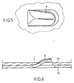
- lugs (6) are located in the concave portion (1e) of the slide ( Figure 2). These pins (6) are obtained by cutting the sheet of the slide and by deformation of the cut tabs towards the interior. These tabs (6) have a longitudinal axis (A) parallel to the longitudinal axis (L) of the slide, and are oriented towards the middle of the slide. Complementarily, and therefore on the same generators, the opposite end of the slide has superimposable holes (7) to the pins (6).
- each lug (6) is slightly bent along its longitudinal axis (A) to improve its resistance and decrease its width, and thus facilitate its introduction into the complementary hole (7). In this way, as illustrated in FIG. 6, the hooking of the lug (7) is made safer.
- the central part of the concave part (1e) is pierced with a orifice (8) intended to receive the member for securing with the support (2).
- this orifice (8) is slightly oblong for allow a position correction during the installation of the slide (1) on the support (2).
- the invention also relates to a method of setting places such slides.
- the presence of pins facilitates the installation of these.
- the process according to the invention consists in depositing along the roadway, a succession of slides (1, 1 ', 1 ", ). It is important to deposit these in engaging the pins (6) of the running slide (1) in the holes complementary (7) of the previous slide (1 '), already deposited. Of the so, we create a train of pre-secured slides.
- a twist is produced on the train (1, 1 ', 1 ", ...) of slides which rotates it and presents it vertically, i.e. in the orientation ready for installation.
- browsing the runners we automatically detect the position of the oblong holes (8) at the overlap areas (1a, 1b).
- a support (2) is beaten.
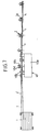
- Such a method can be implemented using a machine (10) characteristic of the invention.
- This chassis (10a) receives in its front part and laterally, a clearance rollers (10b) forcing the passage of the slide train from one orientation horizontal or flat, in a vertical orientation.
- this machine includes a threshing device (10c) arranged offset on one side of the frame (10a).
- This device threshing consists mainly of a hammer (or sheep) (10v1) mounted on a vertical axis (10c2).
- the part of the hammer (10c1) intended for coming into contact with the support (2) is enveloping, that is to say that it covers the upper end of the support and allows vertical retention of the support, preventing it from tipping over.
- the lower part of the threshing unit includes a guide bracket (10d) intended to maintain the lower end of the support (2) at the start of threshing.
- This stirrup (10d) can take the approximate shape of a horseshoe open towards the rear of the direction of movement of the chassis.
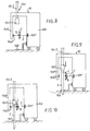
- the frame (10a) has guide elements (10e). optics allowing the installation of supports at positions and heights optimal.
- these guide elements are constituted by a housing light (10e1) emitting a focused optical beam (F).
- the direction of this beam (F) is perpendicular to the plane formed by the different supports (2) already beaten.
- the height of it is very exactly that at which the fastening point (8) of the slide must be located and of the support (2).
- the optical box (10e1) is associated with a reflector (10e2) arranged on an extension arm of the chassis (10a1), on the other side of the final location of the slide (1).
- a support (2) is then introduced into the stirrup (10d) and the device threshing (10c) is then activated. Insertion of the support (2) causes the attachment light (2a) to descend (figure (9).
Landscapes
- Architecture (AREA)
- Civil Engineering (AREA)
- Structural Engineering (AREA)
- Engineering & Computer Science (AREA)
- Insertion Pins And Rivets (AREA)
- Photoreceptors In Electrophotography (AREA)
- Numerical Control (AREA)
- Manufacturing Of Magnetic Record Carriers (AREA)
- Devices Affording Protection Of Roads Or Walls For Sound Insulation (AREA)
- Bridges Or Land Bridges (AREA)
- Packaging Of Machine Parts And Wound Products (AREA)
- Body Structure For Vehicles (AREA)
- Casting Support Devices, Ladles, And Melt Control Thereby (AREA)
- Conveying And Assembling Of Building Elements In Situ (AREA)
- Road Signs Or Road Markings (AREA)
- Refuge Islands, Traffic Blockers, Or Guard Fence (AREA)
- Machines For Laying And Maintaining Railways (AREA)
Claims (10)
- Leitplanke (1) für den Einbau zwischen zwei in den Seitenstreifen einer Straße befestigten Pfosten (2), die an jedem Ende einen überlappenden Bereich (1a, 1b) umfaßt, der einerseits mit Hilfe von Bauteilen (5), die von Leitplanke zu Leitplanke sich gegenüberliegende Bohrlöcher (3, 4) durchqueren, die feste Verbindung mit den angrenzenden Leitplanken (1', 1") ermöglicht, und der andererseits mittels Bauteilen, die zu diesem Zweck in jeder Leitplanke einander gegenüberliegend vorgesehene Öffnungen (8) durchqueren, die feste Verbindung mit den Pfosten (2) ermöglicht, dadurch gekennzeichnet, dass einer der überlappenden Bereiche (1a) mindestens eine Nase (6) aufweist, die in die Längsachse (L) der Leitplanke zu deren Mitte hin ausgerichtet ist, und dass der andere Bereich (1b) an der die Nase (6) aufnehmenden Mantellinie (G2) einen Schlitz (7) für die Aufnahme der Nase (6) der angrenzenden Leitplanke (1') besitzt.
- Leitplanke nach Anspruch 1, dadurch gekennzeichnet, daß die Nasen (6) eingeschnittene Teile sind, die beim Zuschneiden des Blechs der Leitplanke (1) ausgeformt wurden.
- Leitplanke nach Anspruch 2, dadurch gekennzeichnet, daß die Nasen (6) in der Symmetrieachse (A) parallel zur Längsachse (L) der Leitplanke einen Falz aufweisen.
- Leitplanke nach Anspruch 1, dadurch gekennzeichnet, daß sie ein Profil mit zwei konvexen seitlichen Konturen (1c,1d) aufweist, die durch eine mittlere konkave Kontur (1e) verbunden sind, wobei jede Zone (1a) vier Nasen (6) besitzt, die auf der konkaven Kontur (1e) im Rechteck angeordnet sind.
- Leitplanke nach Anspruch 1, dadurch gekennzeichnet, daß die Durchmesser der von einer Leitplanke zur anderen sich gegenüberliegenden Löcher (3, 4) verschieden sind, um die Verbindung durch kegelstumpfartige Bolzen (3) zu ermöglichen.
- Verfahren für das Verlegen von Leitplanken nach einem der vorhergehenden Ansprüche, dadurch gekennzeichnet, daß es nach dem Ablegen einer ersten Leitplanke (1) auf dem Boden in fortlaufender Weise darin besteht:die Nasen (6) der ersten Leitplanke (1') in die komplementären Schlitze (7) der folgenden Leitplanke (1) einzuführen;auf die folgende Leitplanke (1) eine Zugkraft auszuüben, um die Nasen (6) einrasten zu lassen und einen Leitplankenverbund zu bilden;den Leitplankenverbund umzuschwenken, um ihn für die Montage auf den Pfosten senkrecht zu stellen;am Leitplankenverbund automatisch die Öffnungen (8) für die feste Verbindung mit den Pfosten (2) zu erkennen;auf der erfassten Höhe einen Pfosten (2) in den Boden zu schlagen;die Eindringtiefe des Pfostens automatisch zu kontrollieren und das Einschlagen zu beenden, sobald die Ausrichtung der Öffnung (8) der Leitplanken mit einem entsprechenden Loch (2a) des Pfostens erkannt wird;die Leitplanken (1) fest mit dem Pfosten (2) zu verbinden.
- Maschine (10) für die Ausführung des Verfahrens nach Anspruch 6, dadurch gekennzeichnet, daß sie auf einem fahrbaren Rahmen (10a) folgende Teile umfasst:Einrichtungen (10b) zum fortlaufenden Anheben des mit den Nasen (6) fest verbundenen Leitplankenverbunds und zur Senkrechtstellung in die Position für die Montage auf den Pfosten (2);erste Erkennungseinrichtungen (10e) zum Erfassen der Öffnungen (8) für die feste Verbindung mit den Pfosten (2);Einrichtungen (10c) zum Einschlagen eines Pfostens, die mit den Erkennungseinrichtungen verbunden sind und von diesen gesteuert werden;zweite Erkennungseinrichtungen zum Erfassen der Einschlagtiefe der Pfosten (2), die mit den Einschlageinrichtungen verbunden sind und diese steuern.
- Maschine nach Anspruch 7, dadurch gekennzeichnet, daß die Einrichtungen zum Ausrichten des Leitplankenverbunds aus einem System aus Rollen (10b) bestehen, die sich in Vorlaufrichtung der Maschine an deren Vorderteil befinden.
- Maschine nach Anspruch 7, dadurch gekennzeichnet, daß die ersten und zweiten Erkennungseinrichtungen zusammengefaßt sind und aus folgenden Teilen bestehen:einem Lichtstrahler (10e1) am Rahmen (10a) der Maschine, der senkrecht zur Bewegungsrichtung der Maschine und in einer der Befestigungshöhe der Leitplanken entsprechenden Höhe einen Strahl (F) abgibt,einen optischen Sensor (10e2), der an einer Verlängerung (10a1) der Maschine auf der anderen Seite der für die Leitplanke vorgesehenen Stelle angeordnet und geeignet ist, über die Öffnungen (8) des Leitplankenverbunds und (2a) des Pfostens hindurch den Lichtstrahl (F) zu empfangen.
- Maschine nach Anspruch 7, dadurch gekennzeichnet, daß die Einschlageinrichtungen des Pfostens aus einem in einer senkrechten Achse beweglichen Hammer (10c1) bestehen, dessen Kopf eine Form aufweist, die das obere Ende eines Pfostens (2) umschließt, und der mit einem unteren Bügel (10d) für die Führung und Positionierung des unteren Endes des gleichen Pfostens (2) kombiniert ist.
Applications Claiming Priority (3)
| Application Number | Priority Date | Filing Date | Title |
|---|---|---|---|
| FR9603490 | 1996-03-15 | ||
| FR9603490A FR2746120B1 (fr) | 1996-03-15 | 1996-03-15 | Glissiere de securite, procede de mise en place de telle glissiere et machine de mise en oeuvre de ce procede |
| PCT/FR1997/000451 WO1997035070A1 (fr) | 1996-03-15 | 1997-03-13 | Glissiere de securite, procede de mise en place de telle glissiere et machine de mise en oeuvre de ce procede |
Publications (2)
| Publication Number | Publication Date |
|---|---|
| EP0886702A1 EP0886702A1 (de) | 1998-12-30 |
| EP0886702B1 true EP0886702B1 (de) | 2000-05-24 |
Family
ID=9490374
Family Applications (1)
| Application Number | Title | Priority Date | Filing Date |
|---|---|---|---|
| EP97914390A Expired - Lifetime EP0886702B1 (de) | 1996-03-15 | 1997-03-13 | Leitplanken, verfahren zur erstellung und maschine zur durchführung des verfahrens |
Country Status (9)
| Country | Link |
|---|---|
| US (1) | US6036399A (de) |
| EP (1) | EP0886702B1 (de) |
| AT (1) | ATE193350T1 (de) |
| CA (1) | CA2248850A1 (de) |
| DE (1) | DE69702126T2 (de) |
| ES (1) | ES2147984T3 (de) |
| FR (1) | FR2746120B1 (de) |
| PL (1) | PL184917B1 (de) |
| WO (1) | WO1997035070A1 (de) |
Cited By (1)
| Publication number | Priority date | Publication date | Assignee | Title |
|---|---|---|---|---|
| NL2005199C2 (nl) * | 2010-08-06 | 2012-02-07 | Heijmans Techniek & Mobiliteit B V | Geleiderailconstructie alsmede plank daarvoor. |
Families Citing this family (40)
| Publication number | Priority date | Publication date | Assignee | Title |
|---|---|---|---|---|
| ATE329531T1 (de) * | 1999-07-02 | 2006-07-15 | Quickpass Inc | Chirurgisches nähgerät |
| US6575434B2 (en) * | 1999-12-17 | 2003-06-10 | The Texas A&M University System | Apparatus and methods for strengthening guardrail installations |
| NL1014524C2 (nl) * | 2000-02-29 | 2001-08-30 | Lodewijk Petrus Maria Minck | Werkwijze voor het tot stand brengen van een vangrail-constructie en middelen voor toepassing van de werkwijze. |
| FR2815051B1 (fr) * | 2000-10-06 | 2003-03-21 | Henri Schalk | Dispositif de pose de glissieres de securite notamment |
| US6530560B2 (en) | 2000-11-15 | 2003-03-11 | K.E.S.S. Inc. | Guardrail support, attachment, and positioning block |
| CA2428779C (en) | 2000-11-15 | 2009-04-07 | David T. King | Guard rail support, attachment, and positioning spacer block |
| US20030094603A1 (en) * | 2001-11-21 | 2003-05-22 | Lerch James E. | Customized barrier fences having variable post positions |
| USD475145S1 (en) | 2001-12-26 | 2003-05-27 | Thomas E. Melvin | Barrier post |
| ES2349116T3 (es) | 2002-03-20 | 2010-12-28 | Aximum Produits De Securite | Dispositivo de colocacion de barreras de seguridad. |
| AU2002302688A1 (en) | 2002-04-05 | 2003-10-20 | Profil R | Device for setting up guard rails |
| US7234687B2 (en) * | 2003-03-10 | 2007-06-26 | K.E.S.S. Inc. | Guardrail support, attachment, and positioning block |
| ITMI20031691A1 (it) * | 2003-09-02 | 2005-03-03 | Provincia Autonoma Di Trento | Distanziatore per barriera di contenimento stradale o autostradale. |
| US7014389B1 (en) * | 2004-01-30 | 2006-03-21 | Hallan Products, Ltd. | Articulated guardrail reflector assembly |
| US7478796B2 (en) * | 2004-06-10 | 2009-01-20 | Monroeville Industrial Moldings, Inc. | Guardrail support members |
| US7832713B2 (en) * | 2004-07-06 | 2010-11-16 | K.E.S.S. Inc. | Guard rail mounting block and guard rail system incorporating the same |
| FR2886318B1 (fr) * | 2005-05-30 | 2007-08-17 | Profil R Soc Par Actions Simpl | Glissiere de securite, procede de montage et procede de fabrication d'une telle glissiere |
| US7322549B2 (en) * | 2005-08-29 | 2008-01-29 | Luna-Keaton Melissa M | Refuse container retainer |
| US20070063178A1 (en) * | 2005-09-19 | 2007-03-22 | Alberson Dean C | Guardrail flange protector |
| US20070228350A1 (en) * | 2006-02-07 | 2007-10-04 | Joseph Szuba | Guardrail assembly and method of installing the guardrail assembly |
| US8500103B2 (en) * | 2006-03-01 | 2013-08-06 | The Texas A&M University System | Yielding post guardrail safety system incorporating thrie beam guardrail elements |
| RU2320805C1 (ru) * | 2006-08-02 | 2008-03-27 | Общество с ограниченной ответственностью "Группа компаний "Трансстрой" | Дорожное барьерное ограждение |
| US7878485B2 (en) * | 2007-08-21 | 2011-02-01 | Nucor Corporation | Roadway guardrail system |
| US8353499B2 (en) * | 2007-08-21 | 2013-01-15 | Nucor Corporation | Roadway guardrail system |
| AU2008261143B2 (en) * | 2007-12-21 | 2015-07-02 | Industrial Galvanizers Corporation Pty Ltd | Improved Guard Rail Post |
| ES2661311T3 (es) * | 2009-03-19 | 2018-03-28 | Industrial Galvanizers Corporation Pty, Ltd. | Barrera vial mejorada |
| US8215619B2 (en) | 2009-03-31 | 2012-07-10 | Energy Absorption Systems, Inc. | Guardrail assembly, breakaway support post for a guardrail and methods for the assembly and use thereof |
| MX344178B (es) | 2011-05-30 | 2016-12-08 | Ind Galvanizers Corp Pty Ltd | Construcción mejorada de barrera. |
| US9200417B2 (en) | 2012-11-27 | 2015-12-01 | Energy Absorption Systems, Inc. | Guardrail system with a releasable post |
| WO2017086806A1 (en) * | 2015-11-18 | 2017-05-26 | Troy Wheeler Contracting Limited | A guardrail |
| AU2015261682B2 (en) | 2015-11-27 | 2022-07-14 | Industrial Galvanizers Corporation Pty Ltd | Improved Parking Barrier System and Post |
| US9611601B1 (en) * | 2015-12-17 | 2017-04-04 | Lindsay Transportation Solutions, Inc. | Crash absorbing guardrail panel assembly |
| JP7023101B2 (ja) * | 2017-12-18 | 2022-02-21 | Jfe建材株式会社 | 車両用防護柵のビーム材及びビーム材設置方法 |
| JP7042607B2 (ja) * | 2017-12-18 | 2022-03-28 | Jfe建材株式会社 | 車両用防護柵のビーム材及び車両用防護柵 |
| PL240118B1 (pl) * | 2018-04-09 | 2022-02-14 | Stalprodukt Spolka Akcyjna | Połączenie klinowe odcinków odbojnicy drogowej bariery ochronnej |
| AU2019206002B2 (en) | 2018-07-26 | 2025-05-08 | Industrial Galvanizers Corporation Pty Ltd | Improved Spacer Piece for a Guard Rail System |
| US11466415B2 (en) | 2018-12-07 | 2022-10-11 | Dean L. Sicking | Guardrail terminal |
| GB2588223B (en) * | 2019-10-17 | 2023-11-15 | Hill & Smith Ltd | Beam Connection device |
| BR112022023819A2 (pt) * | 2020-06-05 | 2022-12-20 | Valtir Llc | Amortecedor de choque |
| CN113463545B (zh) * | 2021-05-27 | 2022-04-26 | 广州桃园景观工程有限公司 | 一种高速公路安全防护栏及其施工工艺 |
| US20230137587A1 (en) * | 2021-10-28 | 2023-05-04 | Fireproof, LLC | Fencing attachment devices |
Family Cites Families (4)
| Publication number | Priority date | Publication date | Assignee | Title |
|---|---|---|---|---|
| FR1429838A (fr) * | 1965-04-08 | 1966-02-25 | Longrine, destinée plus particulièrement à une barrière de sécurité pour voies routières | |
| US4330106A (en) * | 1979-05-02 | 1982-05-18 | Chisholm Douglas B | Guard rail construction |
| US5489162A (en) * | 1993-02-10 | 1996-02-06 | Digital Equipment Corporation | Fastening |
| FR2704255B1 (fr) * | 1993-04-20 | 1995-07-13 | Lorraine Laminage | Armature pour le renforcement de structures en beton et procede de fabrication de cette armature. |
-
1996
- 1996-03-15 FR FR9603490A patent/FR2746120B1/fr not_active Expired - Fee Related
-
1997
- 1997-03-13 WO PCT/FR1997/000451 patent/WO1997035070A1/fr not_active Ceased
- 1997-03-13 CA CA002248850A patent/CA2248850A1/fr not_active Abandoned
- 1997-03-13 PL PL97328972A patent/PL184917B1/pl not_active IP Right Cessation
- 1997-03-13 AT AT97914390T patent/ATE193350T1/de not_active IP Right Cessation
- 1997-03-13 EP EP97914390A patent/EP0886702B1/de not_active Expired - Lifetime
- 1997-03-13 US US09/142,717 patent/US6036399A/en not_active Expired - Fee Related
- 1997-03-13 ES ES97914390T patent/ES2147984T3/es not_active Expired - Lifetime
- 1997-03-13 DE DE69702126T patent/DE69702126T2/de not_active Expired - Fee Related
Cited By (1)
| Publication number | Priority date | Publication date | Assignee | Title |
|---|---|---|---|---|
| NL2005199C2 (nl) * | 2010-08-06 | 2012-02-07 | Heijmans Techniek & Mobiliteit B V | Geleiderailconstructie alsmede plank daarvoor. |
Also Published As
| Publication number | Publication date |
|---|---|
| PL328972A1 (en) | 1999-03-01 |
| US6036399A (en) | 2000-03-14 |
| FR2746120A1 (fr) | 1997-09-19 |
| CA2248850A1 (fr) | 1997-09-25 |
| DE69702126D1 (de) | 2000-06-29 |
| EP0886702A1 (de) | 1998-12-30 |
| DE69702126T2 (de) | 2001-01-25 |
| ES2147984T3 (es) | 2000-10-01 |
| PL184917B1 (pl) | 2003-01-31 |
| FR2746120B1 (fr) | 1998-06-12 |
| ATE193350T1 (de) | 2000-06-15 |
| WO1997035070A1 (fr) | 1997-09-25 |
Similar Documents
| Publication | Publication Date | Title |
|---|---|---|
| EP0886702B1 (de) | Leitplanken, verfahren zur erstellung und maschine zur durchführung des verfahrens | |
| EP0184525B1 (de) | Leitplanke | |
| FR2690701A1 (fr) | Glissières de sécurité routières mixtes métal et bois ronds armés. | |
| CA2410924C (fr) | Procede de construction d'une voie ferree sur une dalle de beton et selle provisoire pour la mise en oeuvre de ce procede | |
| FR2749329A1 (fr) | Barriere de securite pour voies routieres et autoroutieres | |
| FR2517646A1 (fr) | Piste pour vehicules sans conducteur | |
| FR2793501A1 (fr) | Dispositif de montage d'une glissiere de securite sur des supports verticaux de fixation au sol | |
| EP1182296B1 (de) | Verkehrsleit- und Schutzplankenanordnung | |
| WO2002086247A1 (fr) | Equipement de voirie pret a l'installation et procede d'installation correspondant | |
| FR2846673A1 (fr) | Glissiere de securite routiere a double file de profiles solidarises entre eux | |
| EP0141750B1 (de) | Zaunsystem, dessen Elemente aus wenigstens einem horizontalen, zwischen zwei runden Pfosten befindlichen Schaftstab bestehen | |
| FR2785309A1 (fr) | Barriere de securite pour voies de circulation de vehicules, comprenant deux lisses superposees a resistances d'enfoncement differentielles | |
| FR2724196A1 (fr) | Dispositif de fixation d'un mat en forme de cylindre creux et mat apte a etre installe a l'aide d'un tel dispositif | |
| FR2459396A1 (fr) | Dispositif de support et de fixation sur glissieres pour des panneaux de signalisation, notamment pour autoroute | |
| FR2833630A1 (fr) | Glissiere de securite bois | |
| EP1347100B1 (de) | Vorrichtung zum Setzen von Leitplanken | |
| FR2636292A3 (fr) | Dispositif pour presenter des vehicules a deux roues | |
| FR2982622A1 (fr) | Dalle en beton de support d'au moins deux files de rails d'une voie ferree et voie ferree equipee d'au moins une telle dalle | |
| FR2707326A1 (fr) | Portail coulissant non suspendu. | |
| FR2862320A1 (fr) | Procede d'absorption de chocs contre une barriere de securite pour voies de circulation et barriere de securite de mise en oeuvre | |
| FR2815051A1 (fr) | Dispositif de pose de glissieres de securite notamment | |
| FR3156153A1 (fr) | Système de clôture | |
| EP1526229B1 (de) | Verbindungsstück zwischen einem Pfosten und einem Querträger und mit diesem Zwischenstück versehener Zaun | |
| EP3619379A1 (de) | Satz von strukturelementen zur bildung eines mehrgeschossigen, oberirdischen parkhauses und entsprechendes mehrgeschossiges oberirdisches parkhaus | |
| WO2003085206A1 (fr) | Dispositif de pose de glissieres de securite |
Legal Events
| Date | Code | Title | Description |
|---|---|---|---|
| PUAI | Public reference made under article 153(3) epc to a published international application that has entered the european phase |
Free format text: ORIGINAL CODE: 0009012 |
|
| 17P | Request for examination filed |
Effective date: 19980909 |
|
| AK | Designated contracting states |
Kind code of ref document: A1 Designated state(s): AT BE CH DE DK ES GB GR IE IT LI NL PT SE |
|
| GRAG | Despatch of communication of intention to grant |
Free format text: ORIGINAL CODE: EPIDOS AGRA |
|
| 17Q | First examination report despatched |
Effective date: 19991125 |
|
| GRAG | Despatch of communication of intention to grant |
Free format text: ORIGINAL CODE: EPIDOS AGRA |
|
| GRAH | Despatch of communication of intention to grant a patent |
Free format text: ORIGINAL CODE: EPIDOS IGRA |
|
| GRAH | Despatch of communication of intention to grant a patent |
Free format text: ORIGINAL CODE: EPIDOS IGRA |
|
| GRAA | (expected) grant |
Free format text: ORIGINAL CODE: 0009210 |
|
| AK | Designated contracting states |
Kind code of ref document: B1 Designated state(s): AT BE CH DE DK ES GB GR IE IT LI NL PT SE |
|
| PG25 | Lapsed in a contracting state [announced via postgrant information from national office to epo] |
Ref country code: NL Free format text: LAPSE BECAUSE OF FAILURE TO SUBMIT A TRANSLATION OF THE DESCRIPTION OR TO PAY THE FEE WITHIN THE PRESCRIBED TIME-LIMIT Effective date: 20000524 Ref country code: IT Free format text: LAPSE BECAUSE OF FAILURE TO SUBMIT A TRANSLATION OF THE DESCRIPTION OR TO PAY THE FEE WITHIN THE PRE;WARNING: LAPSES OF ITALIAN PATENTS WITH EFFECTIVE DATE BEFORE 2007 MAY HAVE OCCURRED AT ANY TIME BEFORE 2007. THE CORRECT EFFECTIVE DATE MAY BE DIFFERENT FROM THE ONE RECORDED.SCRIBED TIME-LIMIT Effective date: 20000524 |
|
| REF | Corresponds to: |
Ref document number: 193350 Country of ref document: AT Date of ref document: 20000615 Kind code of ref document: T |
|
| REG | Reference to a national code |
Ref country code: CH Ref legal event code: EP |
|
| REG | Reference to a national code |
Ref country code: IE Ref legal event code: FG4D Free format text: FRENCH |
|
| REF | Corresponds to: |
Ref document number: 69702126 Country of ref document: DE Date of ref document: 20000629 |
|
| GBT | Gb: translation of ep patent filed (gb section 77(6)(a)/1977) |
Effective date: 20000724 |
|
| PG25 | Lapsed in a contracting state [announced via postgrant information from national office to epo] |
Ref country code: SE Free format text: LAPSE BECAUSE OF FAILURE TO SUBMIT A TRANSLATION OF THE DESCRIPTION OR TO PAY THE FEE WITHIN THE PRESCRIBED TIME-LIMIT Effective date: 20000824 Ref country code: PT Free format text: LAPSE BECAUSE OF FAILURE TO SUBMIT A TRANSLATION OF THE DESCRIPTION OR TO PAY THE FEE WITHIN THE PRESCRIBED TIME-LIMIT Effective date: 20000824 Ref country code: DK Free format text: LAPSE BECAUSE OF FAILURE TO SUBMIT A TRANSLATION OF THE DESCRIPTION OR TO PAY THE FEE WITHIN THE PRESCRIBED TIME-LIMIT Effective date: 20000824 |
|
| PG25 | Lapsed in a contracting state [announced via postgrant information from national office to epo] |
Ref country code: GR Free format text: LAPSE BECAUSE OF FAILURE TO SUBMIT A TRANSLATION OF THE DESCRIPTION OR TO PAY THE FEE WITHIN THE PRESCRIBED TIME-LIMIT Effective date: 20000825 |
|
| REG | Reference to a national code |
Ref country code: ES Ref legal event code: FG2A Ref document number: 2147984 Country of ref document: ES Kind code of ref document: T3 |
|
| NLV1 | Nl: lapsed or annulled due to failure to fulfill the requirements of art. 29p and 29m of the patents act | ||
| PG25 | Lapsed in a contracting state [announced via postgrant information from national office to epo] |
Ref country code: IE Free format text: LAPSE BECAUSE OF NON-PAYMENT OF DUE FEES Effective date: 20010205 |
|
| REG | Reference to a national code |
Ref country code: IE Ref legal event code: FD4D |
|
| PLBE | No opposition filed within time limit |
Free format text: ORIGINAL CODE: 0009261 |
|
| STAA | Information on the status of an ep patent application or granted ep patent |
Free format text: STATUS: NO OPPOSITION FILED WITHIN TIME LIMIT |
|
| PG25 | Lapsed in a contracting state [announced via postgrant information from national office to epo] |
Ref country code: LI Free format text: LAPSE BECAUSE OF NON-PAYMENT OF DUE FEES Effective date: 20010331 Ref country code: CH Free format text: LAPSE BECAUSE OF NON-PAYMENT OF DUE FEES Effective date: 20010331 Ref country code: BE Free format text: LAPSE BECAUSE OF NON-PAYMENT OF DUE FEES Effective date: 20010331 |
|
| 26N | No opposition filed | ||
| BERE | Be: lapsed |
Owner name: S.A. LES PROFILES DU CENTRE - L.P.C. Effective date: 20010331 |
|
| REG | Reference to a national code |
Ref country code: CH Ref legal event code: PL |
|
| REG | Reference to a national code |
Ref country code: GB Ref legal event code: IF02 |
|
| PGFP | Annual fee paid to national office [announced via postgrant information from national office to epo] |
Ref country code: AT Payment date: 20020220 Year of fee payment: 6 |
|
| PGFP | Annual fee paid to national office [announced via postgrant information from national office to epo] |
Ref country code: GB Payment date: 20020305 Year of fee payment: 6 |
|
| PGFP | Annual fee paid to national office [announced via postgrant information from national office to epo] |
Ref country code: DE Payment date: 20020311 Year of fee payment: 6 |
|
| PGFP | Annual fee paid to national office [announced via postgrant information from national office to epo] |
Ref country code: ES Payment date: 20020313 Year of fee payment: 6 |
|
| PG25 | Lapsed in a contracting state [announced via postgrant information from national office to epo] |
Ref country code: GB Free format text: LAPSE BECAUSE OF NON-PAYMENT OF DUE FEES Effective date: 20030313 Ref country code: AT Free format text: LAPSE BECAUSE OF NON-PAYMENT OF DUE FEES Effective date: 20030313 |
|
| PG25 | Lapsed in a contracting state [announced via postgrant information from national office to epo] |
Ref country code: ES Free format text: LAPSE BECAUSE OF NON-PAYMENT OF DUE FEES Effective date: 20030314 |
|
| PG25 | Lapsed in a contracting state [announced via postgrant information from national office to epo] |
Ref country code: DE Free format text: LAPSE BECAUSE OF NON-PAYMENT OF DUE FEES Effective date: 20031001 |
|
| GBPC | Gb: european patent ceased through non-payment of renewal fee |
Effective date: 20030313 |
|
| REG | Reference to a national code |
Ref country code: ES Ref legal event code: FD2A Effective date: 20030314 |