EP0887555B1 - Procédé pour la détermination du point de fontionnement d'un ventilateur et l'ensembe ventilateur - Google Patents
Procédé pour la détermination du point de fontionnement d'un ventilateur et l'ensembe ventilateur Download PDFInfo
- Publication number
- EP0887555B1 EP0887555B1 EP98107573A EP98107573A EP0887555B1 EP 0887555 B1 EP0887555 B1 EP 0887555B1 EP 98107573 A EP98107573 A EP 98107573A EP 98107573 A EP98107573 A EP 98107573A EP 0887555 B1 EP0887555 B1 EP 0887555B1
- Authority
- EP
- European Patent Office
- Prior art keywords
- pressure
- fan
- measured
- pressure difference
- volume flow
- Prior art date
- Legal status (The legal status is an assumption and is not a legal conclusion. Google has not performed a legal analysis and makes no representation as to the accuracy of the status listed.)
- Expired - Lifetime
Links
- 238000000034 method Methods 0.000 title claims abstract description 28
- 238000005259 measurement Methods 0.000 claims description 17
- 230000003068 static effect Effects 0.000 claims description 14
- 230000006835 compression Effects 0.000 claims description 5
- 238000007906 compression Methods 0.000 claims description 5
- 230000001419 dependent effect Effects 0.000 claims description 5
- 230000008569 process Effects 0.000 claims description 2
- 238000009530 blood pressure measurement Methods 0.000 claims 19
- 238000009434 installation Methods 0.000 description 15
- 210000002445 nipple Anatomy 0.000 description 7
- 238000010079 rubber tapping Methods 0.000 description 5
- 238000001035 drying Methods 0.000 description 3
- 239000000523 sample Substances 0.000 description 3
- 238000012360 testing method Methods 0.000 description 3
- 230000008901 benefit Effects 0.000 description 2
- 238000004364 calculation method Methods 0.000 description 2
- 230000003750 conditioning effect Effects 0.000 description 2
- 239000000428 dust Substances 0.000 description 2
- 230000006870 function Effects 0.000 description 2
- 238000000227 grinding Methods 0.000 description 2
- 238000012545 processing Methods 0.000 description 2
- 239000007787 solid Substances 0.000 description 2
- 238000011144 upstream manufacturing Methods 0.000 description 2
- 206010010774 Constipation Diseases 0.000 description 1
- 230000004323 axial length Effects 0.000 description 1
- 238000011088 calibration curve Methods 0.000 description 1
- 230000008859 change Effects 0.000 description 1
- 238000009833 condensation Methods 0.000 description 1
- 230000005494 condensation Effects 0.000 description 1
- 238000010276 construction Methods 0.000 description 1
- 238000005516 engineering process Methods 0.000 description 1
- 229910052602 gypsum Inorganic materials 0.000 description 1
- 239000010440 gypsum Substances 0.000 description 1
- 238000012423 maintenance Methods 0.000 description 1
- 238000007726 management method Methods 0.000 description 1
- 239000000463 material Substances 0.000 description 1
- 238000000691 measurement method Methods 0.000 description 1
- 230000001404 mediated effect Effects 0.000 description 1
- 238000010327 methods by industry Methods 0.000 description 1
- 238000012546 transfer Methods 0.000 description 1
- 230000007704 transition Effects 0.000 description 1
- XLYOFNOQVPJJNP-UHFFFAOYSA-N water Chemical compound O XLYOFNOQVPJJNP-UHFFFAOYSA-N 0.000 description 1
Images
Classifications
-
- F—MECHANICAL ENGINEERING; LIGHTING; HEATING; WEAPONS; BLASTING
- F04—POSITIVE - DISPLACEMENT MACHINES FOR LIQUIDS; PUMPS FOR LIQUIDS OR ELASTIC FLUIDS
- F04D—NON-POSITIVE-DISPLACEMENT PUMPS
- F04D27/00—Control, e.g. regulation, of pumps, pumping installations or pumping systems specially adapted for elastic fluids
- F04D27/001—Testing thereof; Determination or simulation of flow characteristics; Stall or surge detection, e.g. condition monitoring
-
- F—MECHANICAL ENGINEERING; LIGHTING; HEATING; WEAPONS; BLASTING
- F05—INDEXING SCHEMES RELATING TO ENGINES OR PUMPS IN VARIOUS SUBCLASSES OF CLASSES F01-F04
- F05D—INDEXING SCHEME FOR ASPECTS RELATING TO NON-POSITIVE-DISPLACEMENT MACHINES OR ENGINES, GAS-TURBINES OR JET-PROPULSION PLANTS
- F05D2270/00—Control
- F05D2270/30—Control parameters, e.g. input parameters
- F05D2270/301—Pressure
- F05D2270/3015—Pressure differential pressure
Definitions
- the invention relates to a method for determining the operating point of a Fan according to the preamble of claim 1, and a fan arrangement according to the preamble of claim 10.
- the radial fan known from EP-B 0 419 798 has at least one one Flow opening limiting and the associated radial impeller upstream inlet nozzle. At least partially at a measuring point in the area the inner circumference of the inflow nozzle in the area in front of it
- the throughflow opening is designed as a static pressure measuring device Arranged measuring device and a located in the area of the measuring point Nozzle wall opening connected.
- centrifugal fan known from EP-A 0 626 519, they are for measurement the pressure difference points provided in the inlet nozzle in two Layers arranged.
- the object of the invention is a method according to the preamble of claim 1 and a corresponding fan according to the preamble of claim 10 develop a determination of the operating point in the installed state, d. H. without external measuring section and calibration as well as an assessment of the quality of the Enable determination and a high level of reliability and thus a high level Ensure operational security.
- an effective pressure difference ⁇ p M w between two levels in the inflow nozzle or between a level in the inflow nozzle and a location in the vicinity, as well as a total pressure difference ⁇ p M t between the suction side and the pressure side of the Fan measured.
- V ⁇ A ⁇ ((2 / ⁇ ) ⁇ p M W ) the volume flow Mediated, where ⁇ is a nozzle coefficient composed of the flow coefficient ⁇ 'and the expansion number ⁇ , A is the reference cross section of the inflow nozzle and ⁇ is the density of the conveyed gas at the inlet to the fan.
- the setpoint value of the total pressure difference ⁇ p s t belonging to the volume flow V is then determined from an existing operating characteristic curve ⁇ p (V) and compared with the measured total pressure difference ⁇ p M t .
- the operating point and its quality are determined on the basis of the agreement or deviation of the target value ⁇ p s t with the measured value ⁇ p M / t. If the value agrees well with the measured value, the operating point determined from the volume flow V and the total pressure ⁇ p M t is determined with high accuracy. A corresponding accuracy class is assigned.
- the advantage of the method according to the invention is that the operating point of the Fan in the installed state determined with specification of the accuracy classes can be. Unfavorable inflow conditions are considered when determining the Operating point recognized and generally lead to the determination of values less accuracy. Inadmissible operating points can also be used with this Procedures for determining the operating point are determined. It will also gradual failures and total failures of the measuring sensors to Example recognized by clogging measuring points. False alarm is avoided and can be intercepted by qualified warnings.
- the shaft power P M W can also be measured.
- the shaft power P M W is a good measure of the power of the fan impeller applied to convey the gas.
- the motor power P M M of the fan motor can also be measured and converted into the shaft power P M W.
- the setpoint value of the shaft power P S W belonging to the volume flow V is additionally determined from an existing operating characteristic curve P W (V) and compared with the measured shaft power P M W. The agreement or deviation of the setpoint P S W improves the determination of the operating point and its quality.
- the setpoints ⁇ p S t and P S W are according to claim 3 with the aid of transmitted configuration values, such as the nominal diameter D of the fan or dimensions of the inlet nozzle, and measured state values, such as the external pressure Pa, the temperature T, the motor speed n or the speed of the fan wheel n * and determined from model characteristics.
- Model characteristic curves are characteristic curves that are recorded and standardized on a test bench using a fan model, ie they are standardized type characteristic curves. Model characteristics for the pressure figure ⁇ ( ⁇ ), the efficiency ⁇ ( ⁇ ) and possibly the performance figure ⁇ ( ⁇ ) in
- a state variable for example the density p of the conveyed gas
- a state variable for example the density p of the conveyed gas
- the shaft power P M W is also measured in the environment and the total pressure difference ⁇ p M t .
- the determination of the volume flow V and the state value is carried out in iteration steps.
- the comparison of the desired value for the shaft power P S W derived from the determined volume flow V with its measured value P M W enables the assignment of an accuracy class.
- the dependence of the nozzle coefficient ⁇ corresponding to this pressure difference ⁇ p M W on the Reynold number Re in iteration steps can be taken into account when determining the volume flow V from the measured pressure difference ⁇ p M W.
- at least one model characteristic curve ⁇ (Re) measured on a model inflow nozzle installed in a model fan is stored.
- an average nozzle coefficient ⁇ is inserted in the first iteration step.
- a Reynolds number Re can be determined from the volume flow V determined in the first iteration step and a second nozzle coefficient ⁇ can be read from the model characteristic curve ⁇ (Re).
- the second iteration step is carried out with the second nozzle coefficient ⁇ .
- the values determined from the characteristic curves in the form of factors dependent on the operating state of the fan, in particular the factor k to take into account internal losses and / or the factor f can be upgraded or depreciated to take into account the compression of the extracted gas.
- the factors determined from the characteristic curves in the form of factors dependent on the operating state of the fan in particular the factor k to take into account internal losses and / or the factor f can be upgraded or depreciated to take into account the compression of the extracted gas.
- e.g. B. stored on several sizes of the type series of the fan characteristic curves for the factor k depending on the rotational speed u of the fan wheel and characteristic curves or calculation instructions for the factor f depending on the total pressure difference ⁇ p t .
- the consideration of this upgrading or downgrading leads to an even more precise determination of the operating point and is necessary to assign a higher accuracy class.
- a measurement of two differential pressure differences .DELTA.p M w1 / 3 and .DELTA.p M w2 / 3 in the inflow nozzle according to claim 7 enables a check of the quality of the inflow and the measuring points.
- the quality of the inflow is checked by comparing the ratio of the pressure differences ⁇ p M w 1/3 to ⁇ p M w 2/3 with the known value of the square of the reciprocal ratio of the corresponding nozzle coefficients ( ⁇ 2/3 / ⁇ 1/3 ) 2nd
- the operating point can be determined with each of the two pressure differences ⁇ p M w1 / 3 and ⁇ p M w2 / 3 using the assigned flow coefficients ⁇ 1/3 and ⁇ 2/3 determined and stored on the model of a fan with an inflow nozzle . Differences that occur indicate faulty measuring points.
- measuring points can be the mean value for determination the operating point of the fan.
- the character of the inflow by comparing the in the center and at the Inlet nozzle measured pressure and when assigning a Accuracy class are taken into account. If the pressure in the center is less than on the inflow nozzle, the flow is swirling.
- a fan arrangement according to claim 10 is for performing a method according to the Claims 1 to 9, a fan arrangement according to claim 11 is particularly for Implementation of a method according to claim 2 or 3 and fan arrangements according to Claims 13, 14 and 15 are particularly suitable for carrying out processes according to claims 7, 8 and 9 suitable.
- the fan arrangement according to claim 12 simple measuring devices, namely a tachometer, a Temperature sensor and an absolute pressure sensor.
- the inflow nozzle has a further plane A2 Pressure measuring points on and according to claim 14 are in levels A1 to A3 in the Inlet nozzle of the radial fan and in level A4 in the housing of the fan Four pressure measuring points each arranged on a circumference.
- the four Pressure measuring points are, for example, connected to one another by a ring line connected.
- the ring lines are connected to corresponding pressure sensors.
- levels A1, A2 and A3 are static in the center Pressure tapping points, e.g. B. each one attached to three struts static Pressure probe, arranged.
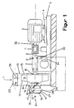
- Figure 1 shows a side view of an arrangement of a Radial fan according to the invention with its motor, being through a housing of the radial fan and a bearing a vertical section through the axis of rotation is placed
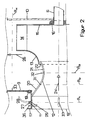
- Figure 2 shows a section perpendicular to the axis of rotation through the Centrifugal fan.
- the inlet nozzle somewhat in FIG. 1 and stronger in FIG. 2 Dimensions stretched parallel to the axis of rotation of the fan wheel.
- Figure 1 shows a one-sided suction radial fan 1 with a bearing 2 and a motor 3.
- the bearing 2 is designed as a bearing block, with a Opening provided plates of a base frame 4 and the motor 3 via a Motor plate 5 attached to this base frame 4.
- a drive shaft 6 starting from the motor 3 is interrupted by a torque measuring device 7 flanged on both sides for measuring the shaft power P M W.
- the drive shaft 6 is guided behind the torque measuring device 7 through the bearing 8 of the bearing 2.
- the radial fan 1 has a housing, one of which is shown in FIGS. 1 and 2
- Lid closure disc 9 and an opposite side wall 10 can be seen are a retracted inflow nozzle with an outer tube section 11 and an inner nozzle section 12 and an impeller with a cover disk 13, Blades 14, a hub disc 15 and a hub 16.
- this hub 16 is inserted through the bearing 8 drive shaft 6 with a snug fit.
- the tube section 11 has an outer connecting flange 17, which Inflow opening 18 limited and its outer diameter also Nominal diameter of the radial fan is called, and an inner Connection flange 19, on which the inflow nozzle on the cover closure disk 9th is attached to.
- the nozzle section 12 of the inflow nozzle is, as in FIG. 2 can be seen more clearly at the inner end of the Pipe section 11 inserted a little into this and seamless with it welded.
- the inflow nozzle is when attaching its inner Connection flange 19 together with the cover plate 13 of the impeller and centered with the impeller.
- the nozzle section 12 of the inflow nozzle starts from the pipe section 11 an inlet cone 20 and a circular arc section 21 which has a nozzle neck and forms a diffuser and its narrowest diameter is approximately in the middle located on.
- the axial extent of the inlet cone 20 is approximately half as large like that of the circular arc section 21.
- the inlet cone 20 connects tangentially the circular arc section 21.
- the inner end of the circular arc section 21 projects into the cover disk 13. Between circular arc section 21 of nozzle section 12 and cover disk 13 remains a small rotating, by centering the inlet nozzle with the Cover plate 13 constant wide air gap 22 free.
- the housing of the radial fan has a rectangular outflow opening 23 on, which is arranged perpendicular to the inflow opening 18 and from the Lid closure disc 9 and the side wall 10 and one not to be seen Housing shell is limited.
- the cross-sectional areas of the rectangular The outflow opening 23 and the round inflow opening 18 are of the same size.
- the tube section 11 of the inlet nozzle are in one in its outer half Level A1 perpendicular to the inflow direction 24 four evenly distributed on the circumference Holes 25.
- the positions of the holes 25 are on the Outflow direction 26 oriented.
- the through holes 25 are either parallel to Outflow direction 26 or arranged perpendicular to it.
- the through holes 25 can also be arranged so that an over an angle of 60 ° extending circumferential area of the inflow nozzle, measured against the Spiral opening starting from the longitudinal axis of the housing outlet crossing at right angles, radially with respect to the longitudinal axis of the nozzle extending radial axis or line remains free of perforations.
- a Bore 25 could be in the circumferential area in the direction of the spiral opening starting from the radial line mentioned above.
- the diameter of the through holes 25 is 2 to 4 mm, here 3 mm.
- the Bores 25 are sharp-edged and deburred to the inner wall.
- the Holes 25 are outside of pipe nipples 27 which are gas-tight with the Pipe section 11 are connected, overhanging.
- the outside diameter of the Pipe nipple 27 is 6 mm, for example.
- the four pipe nipples 27 are interconnected by a ring line 28. From the ring line 28 leads a connecting line 29 to an outside of the inlet nozzle, namely on Base frame 4 below the storage 2 between the two plates in Protected position arranged pressure sensor 30.
- nozzle section 12 In the nozzle section 12 are in a plane A2 parallel to the plane A1, which is in the Inlet cone 20 is located near the transition to the circular arc section 21, and in a plane A3 the narrowest diameter of the circular arc section 21 also four each, at the same angles on the circumference as the through holes 25 arranged through holes 31, 32.
- These through holes 31, 32 are each provided with pipe nipples, a ring line and a connecting line.
- the Pipe nipples, the ring and connecting lines are not shown.
- the connecting line of the through holes 32 of the plane A3 is also at the Differential pressure sensor trained pressure sensor 30 connected.
- the Pressure sensor 30 is another, also as a differential pressure sensor trained (not shown) pressure sensor to which the connecting line of the holes 31 of the level A2 and the connecting line of the Bores 32 of the A3 plane are connected.
- Absolute pressure sensor arranged to measure the ambient pressure Pa.
- a switch box 34 in which a Microcontrollers, signal conditioning devices such as frequency converters and Amplifier, and a power supply, e.g. B. there is a battery, arranged.
- the microcontroller is connected to a via a BUS line Data processing device, for example a PC, connected.
- BUS line Data processing device for example a PC
- the speed sensor 36 can also be on the impeller of the radial fan 1 be arranged.
- the torque measuring device 7 is also via a line (not shown) and the interface connected to the microcontroller.
- the Nominal diameter D of the radial fan 1 is 800 mm
- the diameter of the outer connecting flange 17 is 800 mm
- the inner diameter 788 mm the narrowest diameter of the nozzle section 11,577 mm
- the diameter of the Cover disk 13 of the impeller 629 mm the axial length of the tube section 11 the inflow nozzle 180 mm and that of the nozzle section 12 261 mm.
- the Circular arc section 20 corresponds to an arc of 72 ° with a radius of 150 mm.
- the angle between the pipe section 11 and the inlet cone 20 of the Nozzle section 12 is 36 °.
- the area ratios A1: A2: A3 are 1: 0.81: 0.52
- Static pressure tapping points are located in the center of levels A1 to A3, only the static pressure tapping point 37 of the level A1 in FIG. 2 is located, arranged.
- the static pressure tapping point 37 is on three struts attached static pressure probe.
- the memory of the microcontroller contains standardized type characteristics ⁇ ( ⁇ ), ⁇ ( ⁇ ), if necessary. also ⁇ ( ⁇ ), also called model characteristics, for the type series of Radialventialtors 1.
- ⁇ is the flow number
- ⁇ ( ⁇ ) the pressure number
- ⁇ ( ⁇ ) the Efficiency
- ⁇ ( ⁇ ) the delivery figure.
- the type curves were made Test bench characteristics, for a geometrically similar model radial fan, for example with the nominal diameter of 400 mm.
- the memory of the microcontroller also contains the Reynold number Re dependent dimensionless nozzle coefficients ⁇ (Re) for differential pressures between the Levels A1 and A3 and between levels A2 and A3, and thus characteristic curves for the inlet nozzle.
- These flow coefficients ⁇ (Re) were obtained from measurements in an Model radial fan built-in geometrically similar built-in nozzle derived.
- the memory contains characteristic curves for the factor k to take account of internal losses as a function of the circulation speed of the radial fan 1, which were measured on several sizes of the type series of the radial fan 1, as well as calculation instructions for the factor f to take into account the compression of the delivered gas as a function of the Total pressure difference ⁇ P t deposited.
- the microcontroller memory also contains configuration values such as the Nominal diameter D (800 mm), the installation situation, the gas type and the Solids loading.
- a radial fan according to the invention can in the Levels 1, 2, 3 and 4, instead of four holes, only one hole each to be appropriate. This piercing should, for example, to avoid Constipation due to condensation, at levels 1, 2 and 3 in the upper one Half of the inlet nozzle should be arranged.
- the measured values for the pressure difference ⁇ p M w1 / 3 , optionally the pressure difference ⁇ p M w2 / 3 , the total pressure difference ⁇ p M t and, if appropriate, the shaft power P S W and the measured values of the state values are first, for example of the external pressure Pa, the temperature T, the speed n of the motor 3 or _ of the fan wheel n *.
- the measured value for the shaft power P M W is calculated from the measured torque M M when the torque measuring device 7 is present.
- a second pressure difference ⁇ p M w2 / 3 is also measured, the ratio of the pressure differences ⁇ p M w 1/3 / ⁇ p M w 2/3 with the square of the reciprocal ratio the corresponding mean nozzle coefficients ( ⁇ 2/3 / ⁇ 1/3 ) 2 are compared.
- a match within + -10% indicates a sufficiently undisturbed flow in the inflow nozzle and functioning measuring points, ie here free bores 25, 31, 32.
- the volume flow V is determined according to equation (1) from the differential pressure difference ⁇ p M w 1/3 .
- V ⁇ 1.3 A 3 ⁇ ((2 / ⁇ ) .DELTA.p M w 1/3 )
- ⁇ 1/3 is the nozzle coefficient for the flow conditions between planes A1 and A3 in the inflow nozzle
- a 3 is the cross section of the inflow nozzle in measurement plane A3
- ⁇ is the density of the delivered gas.
- a 3 is known as one of the configuration values.
- the density ⁇ can be determined when air is conveyed from the temperature T measured in the inflow nozzle and the measured external pressure Pa.
- the volume flow V could also be determined from the pressure difference ⁇ p M w 2/3 with the corresponding nozzle coefficient ⁇ 2/3 .
- the dependence of the nozzle coefficients ⁇ 1/3 and ⁇ 2/3 on the Reynolds number Re can be taken into account by starting the determination of the volume flow V with an average nozzle coefficient ⁇ , calculating a Reynolds number Re from the volume flow V determined and the associated nozzle coefficient ⁇ is used to determine the volume flow V again.
- the configuration values inlet cross-section A D , nominal diameter D and the viscosity ⁇ of the pumped gas, here the air are required. After a few iteration steps, the values for the volume flow V and the corresponding nozzle coefficient ⁇ correspond.
- the inlet cross-sectional area A D and the circulation speed u of the fan wheel calculated from the state value of the speed n of the motor 3 or the fan wheel n * and the flow rate figure ⁇ and the pressure figure from the model characteristic curve can be calculated using the configuration value Find ⁇ ( ⁇ ).
- the values of the model characteristic curves can be upgraded or downgraded in order to determine the operating point precisely.
- the measured dependency of an upgrade or depreciation factor k ( ⁇ or> 1) on a variable dependent on the circulation speed u of the fan wheel, the nominal diameter D and the viscosity ⁇ is used.
- an upgrade or depreciation factor f is used depending on the measured total pressure difference ⁇ p M t .
- a value for the efficiency ⁇ ( ⁇ ) can be read from the model characteristic curve from the determined volume flow V and the pressure figure iffer derived from it. This value may also be upgraded or depreciated by the factors k and f.
- the nominal value for the shaft power P S W results from the volume flow V, the total pressure difference ⁇ p M t the value for the efficiency ⁇ ( ⁇ ) and possibly the factors k and f. This value P S W is compared with the measured shaft power P M W to assess the quality of the operating point determination.
- the measured torque M M is converted into the shaft power P M W.
- a good agreement ( ⁇ 2% deviation) indicates a high accuracy class.
- a measuring device for the motor power P M M with devices for measuring the current I M absorbed by the motor 3, the supply voltage U and the power factor cos ⁇ can also be used.
- the measured value for the motor power P M M is calculated from the current consumption I M of the motor 3, the voltage U, the power factor cos ⁇ and the efficiency ⁇ m of the motor 3 and with the aid of an efficiency ⁇ a also stored in the shaft power P M W converted. Because the efficiencies ⁇ m are only approximately known, only a lower accuracy class can be assigned if only the measured and the setpoint values P M W and P S W match.
- a method for determining the operating point and a state variable, namely the density p of the gas conveyed, differs from the method described above in that the determination of the volume flow V and the density ⁇ using one of the pressure differences ⁇ p M w 1/3 or ⁇ p M w 2/3 and the total pressure difference ⁇ p M t is carried out in several iteration steps.
- an initial density p is calculated, for example calculated from the temperature T and the external pressure Pa.
- the dependence of the nozzle coefficient ⁇ 1/3 or ⁇ 1/3 on the Reynolds number Re is taken into account by iteration in each iteration step.
- the result is a volume flow V, a corresponding flow figure ⁇ , factors k, f and the density ⁇ , from which the air humidity can be calculated if necessary.
- the shaft power P s W is determined from the available values and compared with the measured shaft power P M W and an accuracy class is assigned.
- a radial fan according to the invention with a nominal diameter of 800 mm is in a system that sucks up the dust from a planing and grinding line, built-in.
- the radial fan's inlet nozzle is on a straight one Pipe section with a diameter of 800 mm and a length of 5 m flanged.
- In front of the outflow opening 23 is a rectangular channel and over it a transfer element a pipe leading to a filter (with control flap) connected.
- the radial fan has a measuring device for the motor power P M M with devices for measuring the current I, the voltage U and the power factor cos ⁇ instead of a torque measuring device.
- the configuration value efficiency ⁇ m of the motor 3 and the efficiency ⁇ a are stored in the microcontroller to determine the measured shaft power P M W.
- the volume flow V is determined in accordance with equation (1a) from the differential pressure ⁇ p M W1 / 3 , the density ⁇ required for this being calculated from the measured temperature T and the measured external pressure Pa.
- the dependency of the nozzle coefficient ⁇ 1/3 on the Reynolds number Re determined in the model characteristic curve is taken into account by an iterative determination of the volume V and the nozzle coefficient ⁇ 1/3 , starting with an average nozzle coefficient ⁇ 1/3 .
- the flow figure ⁇ is determined from this volume flow V with the aid of configuration and status values and the pressure figure ⁇ ( ⁇ ) from the model characteristic curve. This value is upgraded or depreciated by the determined factors k and f and used to determine the target value of the total pressure difference ⁇ p S t .
- This total pressure difference ⁇ p S t is compared with the measured total pressure difference ⁇ p M t .
- the deviation of the two values is 0.8%.
- a value for the efficiency ⁇ ( ⁇ ) is also read from the model characteristic curve from the flow rate ⁇ determined above and is upgraded or depreciated by the factors k and f.
- the nominal value of the shaft power P S W is calculated from this value and the value for the shaft power P M determined from the measured current consumption I M using the operating voltage U, the power factor cos ⁇ , the efficiency of the motor ⁇ m and the efficiency ⁇ a W compared.
- the measured shaft power P M W is 5.6% above the nominal value of the shaft power P S W derived from the volume flow V.
- the somewhat higher value of the measured shaft power P M W could be due to the additional solids conveyance due to the planing and grinding dust.
- the determination of the measured shaft power P M W via the current consumption M is less precise because of the only approximately known efficiency.
- a radial fan 1 according to the invention also with a nominal diameter of 800 mm is in a drying system to convey exhaust air to one Heat exchanger installed.
- the installation situation leads to a swirl-free attachment and Outflow of the exhaust air, which has a variable water vapor content and a variable Temperature T.
- the speed n * of the fan wheel is one Humidity control set via a frequency converter.
- the radial fan 1 has a torque measuring device 7 and on its motor 3 Current measuring device.
- the ratio of the pressure differences ⁇ p M w 1/3 / ⁇ p M w 2/3 with the known square of the reciprocal ratio of the corresponding nozzle coefficients ( ⁇ 2/3 / ⁇ 1/3 ) is first checked to check the flow and the measuring points. 2 compared. The two values agree within 10%. From this it can be concluded that the measuring points are working and that the inflow, as assumed by the installation situation, is swirl-free.
- the volume flow V and the density p required for this are determined from the pressure difference ⁇ p M w 1/3 with the aid of the measured total pressure difference ⁇ p M t in iteration steps, taking into account the dependence of the nozzle coefficient ⁇ 1/3 on the Reynolds number Re iteratively in each iteration step becomes.
- a value for the density p calculated from the temperature T and the ambient pressure Pa is started.
- a value for the volume flow V and the nozzle coefficient ⁇ 1/3 is determined iteratively from ⁇ p M w 1/3 .
- the flow figure ⁇ is determined from the volume flow V and the value of the pressure figure ⁇ ( ⁇ ) is derived from the model characteristic curve.
- the revaluation or depreciation factors k and f are determined.
- a value for the density ⁇ is calculated, with which the second iteration step is carried out. After a few iteration steps, there are no more deviations in the values of the volume flow V and the density ⁇ .
- the determined value of the flow figure ⁇ is also available.
- the shaft power P S W is calculated from the derived value for the efficiency ⁇ ( ⁇ ), the already known factors k and f and the total pressure difference ⁇ p M t and with the shaft power P determined from the torque M M , ie with the measured one M W compared.
- the measured value P M W is only 3.5% higher than the calculated value P S W. This suggests an exact determination of the volume flow V and the total pressure difference ⁇ p M t .
- the determination of the operating point corresponds to an accuracy class of 0.
- the measured shaft power P M W is determined with the aid of a device for measuring the current consumption P M M from the current consumption of the motor 3 of the radial fan 1, the condition values of operating voltage U and power factor cos ⁇ and the configuration values of efficiency ⁇ m of the motor 3 and efficiency ⁇ a ,
- This measured value P M W is about 10% above the calculated value P S W.
- This deviation and the less precise determination of the measured shaft power P M W with the aid of a current measuring device would assign the operating point determination to an accuracy class of 2 in the case of an exclusive determination of the measured shaft power P M W with the aid of a current measurement I M and a determination of the motor power P M M lead.
- the ratio of the pressure differences ⁇ p M w 1/3 / ⁇ p M w 2/3 is compared with the square of the reciprocal ratio of the corresponding nozzle coefficients ( ⁇ 2/3 / ⁇ 1/3 ) 2 .
- the ratio of the pressure differences ⁇ p M w 2/3 / ⁇ p M w 2/3 is slightly higher than its nominal value, but is within the tolerance range of + -10% deviation. From this it can be concluded that the measuring points are working. A completely swirl-free flow cannot be assumed due to the upstream manifold.
- the volume flow V is determined from the pressure difference ⁇ p M w 1/3 , the dependence of the nozzle coefficient ⁇ 1/3 being taken into account by iteration steps as in the previous examples.
- the flow figure ⁇ , the pressure figure ⁇ ( ⁇ ), the up or down valuation factors k and f and finally the total pressure difference ⁇ p S t are derived from the volume flow V.
- the measured value for the total pressure difference ⁇ p M t is (by about 8.9%) significantly below this calculated value ⁇ p S t .
- the measured value of the shaft power P M W determined from the current consumption I M is (by about 6.5%) lower than that from the volume flow V, the flow rate ⁇ , the efficiency ⁇ ( ⁇ ), the factors k and f and the measured total pressure difference ⁇ p M t calculated setpoint for the power P S W.
- An accuracy class of 2 is assigned to the determined operating point with the calculated volume flow V and the measured total pressure difference ⁇ p M t due to the inaccuracy due to the changed flow profile. Since both setpoints ⁇ p S t and P S W are higher than their measured values, the flow can be described by characteristic curves shifted to lower values. A higher accuracy of the determination of the operating point with V and ⁇ p M t is likely.
- a current measuring device In front of the inflow nozzle of a radial fan 1 according to the invention with a Nominal diameter of 800 mm and a current measuring device is one for one Swirl-free inflow, sufficiently long inflow pipe arranged.
- the ratio of the pressure differences ⁇ p M w1 / 3 / ⁇ p M w2 / 3 is compared with the square of the reciprocal ratio of the corresponding nozzle coefficients ( ⁇ 2/3 / ⁇ 1/2 ) 2 .
- the ratio of the pressure differences ⁇ p M w 1/3 / ⁇ p M w 2/3 is about 20% lower than its setpoint. From this, a fault can already be concluded.
- the volume flow V is also determined from the pressure difference ⁇ p M w 2/3 .
- This volume flow V and the values derived therefrom for the total pressure difference ⁇ p S t and the power P S M agree well with the corresponding measured values ⁇ p M t and P M w .
- the accuracy class from 0 to 1 is assigned to this determination. This information is saved with a corresponding warning and displayed if necessary.
Landscapes
- Engineering & Computer Science (AREA)
- Mechanical Engineering (AREA)
- General Engineering & Computer Science (AREA)
- Control Of Positive-Displacement Air Blowers (AREA)
- Measuring Volume Flow (AREA)
- Control Of Electric Motors In General (AREA)
Claims (15)
- Procédé pour déterminer le point de fonctionnement d'un ventilateur dans lequel une différence de pression effective ΔpM W est mesurée avec au moins un point de mesure sur une buse d'entrée du ventilateur et le débit volumique V est calculé à partir de là, la différence de pression effective ΔpM W étant mesurée entre deux plans de la buse d'entrée ou entre un plan de la buse d'entrée et un point dans l'environnement,
caractérisé en ce que
une différence de pression totale ΔpM t est, en outre, mesurée entre le côté aspiration et le côté refoulement du ventilateur,
une valeur de consigne établie à partir du débit volumique V via une caractéristique de fonctionnement Δpt (V) pour la différence de pression totale ΔpS t est comparée avec la différence de pression totale ΔpM t mesurée,
et le point de fonctionnement et sa qualité sont déterminés à partir de la comparaison. - Procédé selon la revendication 1 caractérisé en ce que
la puissance à l'arbre PM W du ventilateur est, en outre, mesurée,
une valeur de consigne établie à partir du débit volumique V via une caractéristique de fonctionnement PW (V) pour la puissance à l'arbre PS W est comparée avec la puissance à l'arbre PM W mesurée et
la comparaison supplémentaire est utilisée pour déterminer le point de fonctionnement et sa qualité. - Procédé selon la revendication 1 ou 2 caractérisé en ce que le débit volumique V et les valeurs de consigne des caractéristiques de fonctionnement ΔpS t et PS W sont établies à l'aide des caractéristiques modèles Ψ(), η() et, le cas échéant de λ(), de valeurs de configuration et de valeurs d'état du ventilateur.
- Procédé selon la revendication 3 pour déterminer le point de fonctionnement d'un ventilateur et sa valeur d'état, comme par exemple la densité p du gaz transporté pour lequel une différence de pression effective ΔpM W est mesurée avec au moins un point de mesure sur une buse d'entrée du ventilateur et le débit volumique V est déterminé à partir de là,a) la différence de pression effective ΔpM W étant mesurée entre deux plans de la buse d'entrée ou entre un plan de la buse d'entrée et un point dans l'environnement etb) le débit volumique V étant calculé à partir de la différence de pression effective ΔpM W à I 'aide de valeurs de configuration et de valeurs d'état mesurées sur le ventilateur,
caractérisé en ce quec) une différence de pression totale ΔpM t entre le côté aspiration et le côté refoulement du ventilateur et la puissance à l'arbre PM W du ventilateur sont, en outre, mesurées,d) une valeur pour l'indice d'alimentation est établie à partir du débit volumique V et une valeur de la caractéristique modèle Ψ() est calculée à partir de là,e) la valeur d'état à déterminer est établie à l'aide de la valeur calculée de la caractéristique modèle Ψ(), le cas échéant, de valeurs de configuration et de valeurs d'état ainsi que de la différence de pression totale ΔpS t mesurée,f) si, lors du calcul du débit volumique V à partir de la différence de pression effective ΔpM t en b), la valeur d'état à déterminer est nécessaire, une détermination du débit volumique V et de la valeur d'état est effectuée par les étapes d'itération b), d) et e),g) une valeur de consigne pour la puissance à l'arbre PS W est établie à partir du débit volumique V calculé sous b), d) et e) à l'aide de la caractéristique modèle η(), le cas échéant, de données de configuration et de données d'état et est comparée avec la puissance PM W mesurée eth) le point de fonctionnement et sa qualité sont déterminés à partir du résultat de b), d) à f) et de la comparaison g). - Procédé selon une des revendications 1 à 4 caractérisé en ce que pour le calcul du débit volumique V à partir de la différence de pression effective ΔpM W, il est tenu compte de la dépendance du coefficient α de la buse correspondant à cette différence de pression effective ΔpM W par rapport au nombre de Reynold à l'aide d'une caractéristique modèle α(Re) de la buse d'entrée à l'état monté par les étapes d'itération.
- Procédé selon une des revendications 1 à 5 caractérisé en ce que pour le calcul des valeurs de consigne de la différence de pression totale ΔpS t et, le cas échéant, de la puissance à l'arbre PS W, les valeurs établies à partir des caractéristiques sous la forme de facteurs dépendant de l'état de fonctionnement du ventilateur, en particulier du facteur k, sont réévaluées ou dévaluées pour tenir compte de pertes internes et / ou du facteur f pour tenir compte de la densification.
- Procédé selon une des revendications 1 à 6 caractérisé en ce que une différence de pression effective ΔpM W 1/3 entre deux plans (A1 et A3) et une différence de pression effective ΔpM W 2/3 entre un plan (A2) se trouvant entre les deux plans (A1 et A3) et le plan (A3) sont mesurées, le débit volumique V étant calculé à partir de la différence de pression effective ΔpM W 1/3 ou de la différence de pression effective ΔpM W 2/3 et la qualité du courant dans la buse d'entrée et / des points de mesure étant déduite, le cas échéant, du rapport des différences de pression.
- Procédé selon une des revendications 1 à 7 caractérisé en ce que les différences de pression sont mesurées chaque fois en quatre points de mesure répartis dans un des plans (A1 à A4) perpendiculaires au sens du courant.
- Procédé selon une des revendications 1 à 8 caractérisé en ce que la pression statique est mesurée au centre des plans (A1, A2 ou A3) dans la buse d'entrée qui sont utilisés pour mesurer les différences de pression.
- Ensemble ventilateur pour déterminer le point de fonctionnement d'un ventilateur selon le procédé des revendications 1 à 9 comprenant un ventilateur avec un moteur, une roue mobile, un logement, une buse d'entrée, qui est pourvu d'au moins un point de mesure pour mesurer une différence de pression effective ΔpM W et d'un dispositif qui y est relié pour traiter les valeurs mesurées, dans lequel pour mesurer une ou plusieurs différences de pression effectives ΔpM W, la buse d'entrée présente un ou plusieurs points de mesure de pression dans au moins deux plans (A1 et / ou A2, A3) perpendiculaires au sens du courant, les points de mesure de pression d'un plan (A1, A2, A3) étant, le cas échéant, reliés entre eux et le point de mesure de pression ou les points de mesure de pression de deux plans (A1 et / ou A2, A3) étant raccordés à un capteur de pression (30), ou
la buse d'entrée présente un ou plusieurs points de mesure de pression dans au moins un plan perpendiculaire au sens du courant et un point de mesure de pression est disposé en un point dans l'environnement, les points de mesure de pression d'un plan étant, le cas échéant, reliés entre eux et le point de mesure de pression ou les points de mesure de pression d'un plan et le point de mesure de pression dans l'environnement étant raccordés à un capteur de pression,
caractérisé en ce que
pour mesurer une différence de pression totale ΔpM t, un logement présente un ou plusieurs points de mesure de pression à proximité de son orifice d'évacuation dans un plan (A4) perpendiculaire au sens d'évacuation (26), les points de mesure de pression étant, le cas échéant, reliés entre eux et le point de mesure de pression ou les points de mesure de pression étant raccordés à un capteur de pression (30) raccordé aux points de mesure de pression de la buse d'entrée d'un des plans (A1 ou A2, A3). - Ensemble ventilateur selon la revendication 10 pour déterminer le point de fonctionnement du ventilateur et, le cas échéant, une grandeur d'état, caractérisé en ce qu'un dispositif de mesure de puissance est disposé sur le ventilateur pour mesurer une puissance à l'arbre PM W.
- Ensemble ventilateur selon la revendication 10 ou 11 caractérisé par un compte-tours (36) pour mesurer la vitesse du moteur n, un capteur de température (35) dans la buse d'entrée pour mesurer la température T et un capteur de pression absolue pour mesurer la pression de l'environnement Pa.
- Ensemble ventilateur selon une des revendications 10 à 12, caractérisé en ce que la buse d'entrée présente, dans un autre plan (A2), un ou plusieurs points de mesure de pression qui sont reliés entre eux et sont raccordés à un capteur de pression (30) raccordé aux points de mesure de pression d'un des plans (A1, A3) de la buse d'entrée.
- Ensemble ventilateur selon une des revendications 10 à 13, caractérisé en ce que quatre points de mesure de pression répartis uniformément sont chaque fois disposés dans les plans (A1 à A4) de la buse d'entrée et du logement.
- Ensemble ventilateur selon une des revendications 10 à 14, caractérisé en ce qu'un point d'échantillonnage de pression statique (37) est chaque fois disposé au centre des plans (A1, A2 ou A3) avec des points de mesure de pression.
Applications Claiming Priority (2)
| Application Number | Priority Date | Filing Date | Title |
|---|---|---|---|
| DE19726547A DE19726547A1 (de) | 1997-06-23 | 1997-06-23 | Verfahren zur Bestimmung des Betriebspunktes eines Ventilators und Ventilator |
| DE19726547 | 1997-06-23 |
Publications (2)
| Publication Number | Publication Date |
|---|---|
| EP0887555A1 EP0887555A1 (fr) | 1998-12-30 |
| EP0887555B1 true EP0887555B1 (fr) | 2004-04-07 |
Family
ID=7833339
Family Applications (1)
| Application Number | Title | Priority Date | Filing Date |
|---|---|---|---|
| EP98107573A Expired - Lifetime EP0887555B1 (fr) | 1997-06-23 | 1998-04-25 | Procédé pour la détermination du point de fontionnement d'un ventilateur et l'ensembe ventilateur |
Country Status (4)
| Country | Link |
|---|---|
| US (1) | US6241463B1 (fr) |
| EP (1) | EP0887555B1 (fr) |
| AT (1) | ATE263926T1 (fr) |
| DE (2) | DE19726547A1 (fr) |
Families Citing this family (22)
| Publication number | Priority date | Publication date | Assignee | Title |
|---|---|---|---|---|
| JP3546173B2 (ja) * | 2000-09-04 | 2004-07-21 | Smc株式会社 | エアブローシステムの機器選定方法及びエアブローシステムの機器選定プログラムを記録した記録媒体 |
| KR100709829B1 (ko) * | 2002-07-23 | 2007-04-23 | 미츠비시 쥬고교 가부시키가이샤 | 캐스크 및 캐스크의 제조 방법 |
| AU2003257324A1 (en) * | 2002-08-16 | 2004-03-03 | Imperial Sheet Metal Ltd. | Proportional control system for a motor |
| US8725299B2 (en) * | 2009-05-21 | 2014-05-13 | Lennox Industries, Inc. | Customer equipment profile system for HVAC controls |
| WO2011009458A1 (fr) * | 2009-07-23 | 2011-01-27 | Skov A/S | Procédé de détermination dun écoulement dair, unité déchappement et son application |
| US8366377B2 (en) * | 2010-04-09 | 2013-02-05 | Trane International Inc. | FC fan flow measurement system using a curved inlet cone and pressure sensor |
| EP2620202B1 (fr) * | 2012-01-30 | 2014-10-29 | ABB Oy | Procédé et appareil de surveillance de condition de filtre à air |
| CN103032359A (zh) * | 2012-12-27 | 2013-04-10 | 上海阿丽贝塑料防腐设备有限公司 | 一种高压全塑风机叶轮动强度测试装置 |
| DE102015000629A1 (de) | 2015-01-22 | 2016-07-28 | Viessmann Werke Gmbh & Co Kg | Turboverdichter |
| CN105736434B (zh) * | 2016-02-02 | 2017-06-30 | 华能国际电力股份有限公司 | 一种电厂风机的性能监控方法与系统 |
| DE102016009598A1 (de) * | 2016-08-09 | 2018-02-15 | Stiebel Eltron Gmbh & Co. Kg | Lüftungsgerät der Haustechnik mit einer Messeinheit |
| DE102016115616A1 (de) * | 2016-08-23 | 2018-03-01 | Ebm-Papst Mulfingen Gmbh & Co. Kg | Strömungsgleichrichter eines Ventilators |
| DE102016118369A1 (de) * | 2016-09-28 | 2018-03-29 | Ebm-Papst Mulfingen Gmbh & Co. Kg | Ansaugdüse und Ausblaseinheit eines Ventilators |
| US10960237B2 (en) | 2017-07-19 | 2021-03-30 | Honeywell International Inc. | Powered air-purifying respirator (PAPR) with eccentric venturi air flow rate determination |
| DE102017120652A1 (de) * | 2017-09-07 | 2019-03-07 | Ebm-Papst Mulfingen Gmbh & Co. Kg | Ventilator mit integrierter Volumenstromregelung |
| DE102018104394A1 (de) * | 2018-02-27 | 2019-08-29 | Ebm-Papst Mulfingen Gmbh & Co. Kg | Arbeitspunktbestimmung |
| DE102020118251A1 (de) * | 2020-07-10 | 2022-01-13 | Ebm-Papst Mulfingen Gmbh & Co. Kg | Verfahren und Ventilatorsystem zur Ermittlung des Zustands eines Filters in einer Ventilatoreinheit |
| PL4185777T3 (pl) * | 2020-07-24 | 2025-10-20 | Zehnder Group International Ag | Układ wentylatora odśrodkowego |
| DE102020213419A1 (de) | 2020-10-23 | 2022-04-28 | Ziehl-Abegg Se | Ventilator zum Bestimmen eines durch den Ventilator bewegten Medienstroms und entsprechendes Verfahren |
| CN112780578B (zh) * | 2021-01-22 | 2022-11-15 | 浙江理工大学 | 离心泵环形密封摩擦因子与损失系数测定装置与方法 |
| CN118273979B (zh) * | 2024-06-03 | 2024-09-06 | 江苏考力特节能风机有限公司 | 一种具有变径喷口的风机 |
| CN119957531B (zh) * | 2024-12-25 | 2025-12-26 | 北京科荣达航空科技股份有限公司 | 机载风扇类产品性能试验台 |
Family Cites Families (22)
| Publication number | Priority date | Publication date | Assignee | Title |
|---|---|---|---|---|
| US3292846A (en) * | 1964-03-30 | 1966-12-20 | Phillips Petroleum Co | Centrifugal compressor operation |
| US3630496A (en) * | 1968-01-26 | 1971-12-28 | Babcock & Wilcox Co | Gas-cleaning apparatus |
| US4158527A (en) * | 1976-08-26 | 1979-06-19 | Ecolaire Incorporated | Adjustable speed drive system for centrifugal fan |
| US4164033A (en) * | 1977-09-14 | 1979-08-07 | Sundstrand Corporation | Compressor surge control with airflow measurement |
| US4203701A (en) * | 1978-08-22 | 1980-05-20 | Simmonds Precision Products, Inc. | Surge control for centrifugal compressors |
| US4405290A (en) * | 1980-11-24 | 1983-09-20 | United Technologies Corporation | Pneumatic supply system having variable geometry compressor |
| DE3105376C2 (de) * | 1981-02-14 | 1984-08-23 | M.A.N. Maschinenfabrik Augsburg-Nürnberg AG, 4200 Oberhausen | Verfahren zum Betreiben von Turboverdichtern |
| US4464720A (en) * | 1982-02-12 | 1984-08-07 | The Babcock & Wilcox Company | Centrifugal compressor surge control system |
| DE3402120A1 (de) * | 1984-01-23 | 1985-07-25 | Rheinhütte vorm. Ludwig Beck GmbH & Co, 6200 Wiesbaden | Verfahren und vorrichtung zur regelung verschiedener betriebsparameter bei pumpen und verdichtern |
| US4586870A (en) * | 1984-05-11 | 1986-05-06 | Elliott Turbomachinery Co., Inc. | Method and apparatus for regulating power consumption while controlling surge in a centrifugal compressor |
| DE3540285A1 (de) * | 1985-11-13 | 1987-05-14 | Gutehoffnungshuette Man | Verfahren und einrichtung zum regeln von turbokompressoren |
| DE3544821A1 (de) * | 1985-12-18 | 1987-06-19 | Gutehoffnungshuette Man | Verfahren zum regeln von turbokompressoren zur vermeidung des pumpens |
| DE3544822A1 (de) * | 1985-12-18 | 1987-06-19 | Gutehoffnungshuette Man | Verfahren zur pumpgrenzregelung von turbokomporessoren |
| DE3703401A1 (de) * | 1987-02-05 | 1988-08-18 | Al Ko Polar Maschf Gmbh | Ventilatorteil sowie verfahren zur funktionskontrolle desselben |
| DE3810717A1 (de) * | 1988-03-30 | 1989-10-19 | Gutehoffnungshuette Man | Verfahren zur vermeidung des pumpens eines turboverdichters mittels abblaseregelung |
| DE8911433U1 (de) * | 1989-09-26 | 1989-11-23 | Gebhardt Ventilatoren GmbH & Co, 7112 Waldenburg | Vorrichtung zur Bestimmung des Volumenstroms eines Radialventilators |
| US5050092A (en) * | 1990-02-26 | 1991-09-17 | Perry Robert E | Fan efficiency measuring apparatus |
| SE500539C2 (sv) * | 1991-06-12 | 1994-07-11 | Flaekt Ab | Sätt och anordning för bestämning av genomströmningsflödet i en ventilationsanläggning med en frisugande fläkt |
| US5195875A (en) * | 1991-12-05 | 1993-03-23 | Dresser-Rand Company | Antisurge control system for compressors |
| US5365459A (en) * | 1992-02-25 | 1994-11-15 | Perry Robert E | Continuous stack flow rate monitor |
| CA2123640A1 (fr) * | 1993-05-17 | 1994-11-18 | Thomas A. Berger | Ventilateur centrifuge a debitmetre |
| US5743715A (en) * | 1995-10-20 | 1998-04-28 | Compressor Controls Corporation | Method and apparatus for load balancing among multiple compressors |
-
1997
- 1997-06-23 DE DE19726547A patent/DE19726547A1/de not_active Withdrawn
-
1998
- 1998-04-25 AT AT98107573T patent/ATE263926T1/de not_active IP Right Cessation
- 1998-04-25 DE DE59811133T patent/DE59811133D1/de not_active Expired - Fee Related
- 1998-04-25 EP EP98107573A patent/EP0887555B1/fr not_active Expired - Lifetime
- 1998-06-22 US US09/102,462 patent/US6241463B1/en not_active Expired - Fee Related
Also Published As
| Publication number | Publication date |
|---|---|
| US6241463B1 (en) | 2001-06-05 |
| EP0887555A1 (fr) | 1998-12-30 |
| DE19726547A1 (de) | 1999-01-28 |
| ATE263926T1 (de) | 2004-04-15 |
| DE59811133D1 (de) | 2004-05-13 |
Similar Documents
| Publication | Publication Date | Title |
|---|---|---|
| EP0887555B1 (fr) | Procédé pour la détermination du point de fontionnement d'un ventilateur et l'ensembe ventilateur | |
| EP0283543B1 (fr) | Appareil de détection de fuites et son fonctionnement | |
| EP2296969B1 (fr) | Système et procédé de surveillance de conduit dans un aéronef | |
| DE69215222T2 (de) | Vorrichtung zur bestimmung des gesamtdurchflusses in einer belüftungsanlage | |
| DE3703401A1 (de) | Ventilatorteil sowie verfahren zur funktionskontrolle desselben | |
| DE2049117A1 (de) | Gasleckanzeigesystem | |
| EP3184754B1 (fr) | Système de détection et procédé de mesure d'une turbomachine | |
| WO2011157622A1 (fr) | Procédé de réglage de fentes radiales se présentant entre les pointes d'aubes mobiles et une paroi de canal, et dispositif de mesure d'une fente radiale d'une turbomachine à flux axial | |
| WO1996017237A1 (fr) | Dispositif de detection de fuites pourvu de pompes a vide et procede permettant son fonctionnement | |
| WO2013087708A2 (fr) | Pompe à vide à anneau liquide pourvue d'un réglage de cavitation | |
| EP0419798B1 (fr) | Dispositif pour déterminer l'écoulement volumique d'un ventilateur radial | |
| EP1288494A1 (fr) | Dispositif pour déterminer la direction du vent | |
| DE3855311T2 (de) | Anordnung zur messung des volumenflusses eines ventilators | |
| DE102017210123A1 (de) | Luftleitsystem sowie Messsystem und Verfahren zum Ermitteln von wenigstens einem Parameter eines aus einem Luftausströmer austretenden Luftstroms | |
| DE19924400C1 (de) | Brandmelder und Verfahren zur Branddetektion | |
| DE102019125070B4 (de) | Verfahren zur Steuerung eines Kältekreislaufs, Kältekreislauf, Wärmemanagementsystem und Fahrzeug | |
| EP3707386B1 (fr) | Stabilité des paramètres | |
| EP0344618B1 (fr) | Dispositif de prélèvement d'échantillon de gaz | |
| EP3927977A1 (fr) | Procédé de détermination quantitative d'une grandeur réelle dépendante de l'état de fonctionnement d'un ventilateur, en particulier d'un changement de pression ou d'une augmentation de pression, et ventilateur | |
| DE102021116154A1 (de) | Überwachungsvorrichtung und Verfahren zur Überwachung der Qualität einer Gasatmosphäre | |
| DE3505385A1 (de) | Kanalgeblaese | |
| DE102020213419A1 (de) | Ventilator zum Bestimmen eines durch den Ventilator bewegten Medienstroms und entsprechendes Verfahren | |
| EP1727970B1 (fr) | Methode et appareil permettant d'etablir l'etat d'un rotor de turbomachine | |
| DE102019219914B4 (de) | Strömungsmaschine und Verfahren zum Erfassen des Abströmwinkels bei Strömungsmaschinen | |
| DE102018108831A1 (de) | Verfahren zum Ermitteln eines Betriebszustandes eines Verdichters |
Legal Events
| Date | Code | Title | Description |
|---|---|---|---|
| PUAI | Public reference made under article 153(3) epc to a published international application that has entered the european phase |
Free format text: ORIGINAL CODE: 0009012 |
|
| AK | Designated contracting states |
Kind code of ref document: A1 Designated state(s): AT BE CH DE ES FR GB IT LI NL SE |
|
| AX | Request for extension of the european patent |
Free format text: AL;LT;LV;MK;RO;SI |
|
| 17P | Request for examination filed |
Effective date: 19990630 |
|
| AKX | Designation fees paid |
Free format text: AT BE CH DE ES FR GB IT LI NL SE |
|
| 17Q | First examination report despatched |
Effective date: 20021106 |
|
| RAP1 | Party data changed (applicant data changed or rights of an application transferred) |
Owner name: GRENZEBACH BSH GMBH |
|
| GRAP | Despatch of communication of intention to grant a patent |
Free format text: ORIGINAL CODE: EPIDOSNIGR1 |
|
| RTI1 | Title (correction) |
Free format text: METHOD FOR DETERMINING THE OPERATING POINT OF A FAN AND THE FAN ARRANGEMENT |
|
| GRAS | Grant fee paid |
Free format text: ORIGINAL CODE: EPIDOSNIGR3 |
|
| GRAA | (expected) grant |
Free format text: ORIGINAL CODE: 0009210 |
|
| AK | Designated contracting states |
Kind code of ref document: B1 Designated state(s): AT BE CH DE ES FR GB IT LI NL SE |
|
| PG25 | Lapsed in a contracting state [announced via postgrant information from national office to epo] |
Ref country code: NL Free format text: LAPSE BECAUSE OF FAILURE TO SUBMIT A TRANSLATION OF THE DESCRIPTION OR TO PAY THE FEE WITHIN THE PRESCRIBED TIME-LIMIT Effective date: 20040407 Ref country code: IT Free format text: LAPSE BECAUSE OF FAILURE TO SUBMIT A TRANSLATION OF THE DESCRIPTION OR TO PAY THE FEE WITHIN THE PRESCRIBED TIME-LIMIT;WARNING: LAPSES OF ITALIAN PATENTS WITH EFFECTIVE DATE BEFORE 2007 MAY HAVE OCCURRED AT ANY TIME BEFORE 2007. THE CORRECT EFFECTIVE DATE MAY BE DIFFERENT FROM THE ONE RECORDED. Effective date: 20040407 Ref country code: GB Free format text: LAPSE BECAUSE OF FAILURE TO SUBMIT A TRANSLATION OF THE DESCRIPTION OR TO PAY THE FEE WITHIN THE PRESCRIBED TIME-LIMIT Effective date: 20040407 Ref country code: FR Free format text: LAPSE BECAUSE OF FAILURE TO SUBMIT A TRANSLATION OF THE DESCRIPTION OR TO PAY THE FEE WITHIN THE PRESCRIBED TIME-LIMIT Effective date: 20040407 Ref country code: ES Free format text: LAPSE BECAUSE OF FAILURE TO SUBMIT A TRANSLATION OF THE DESCRIPTION OR TO PAY THE FEE WITHIN THE PRESCRIBED TIME-LIMIT Effective date: 20040407 |
|
| REG | Reference to a national code |
Ref country code: GB Ref legal event code: FG4D Free format text: NOT ENGLISH |
|
| REG | Reference to a national code |
Ref country code: CH Ref legal event code: EP |
|
| PG25 | Lapsed in a contracting state [announced via postgrant information from national office to epo] |
Ref country code: AT Free format text: LAPSE BECAUSE OF NON-PAYMENT OF DUE FEES Effective date: 20040425 |
|
| PG25 | Lapsed in a contracting state [announced via postgrant information from national office to epo] |
Ref country code: LI Free format text: LAPSE BECAUSE OF NON-PAYMENT OF DUE FEES Effective date: 20040430 Ref country code: CH Free format text: LAPSE BECAUSE OF NON-PAYMENT OF DUE FEES Effective date: 20040430 Ref country code: BE Free format text: LAPSE BECAUSE OF NON-PAYMENT OF DUE FEES Effective date: 20040430 |
|
| REF | Corresponds to: |
Ref document number: 59811133 Country of ref document: DE Date of ref document: 20040513 Kind code of ref document: P |
|
| PG25 | Lapsed in a contracting state [announced via postgrant information from national office to epo] |
Ref country code: SE Free format text: LAPSE BECAUSE OF FAILURE TO SUBMIT A TRANSLATION OF THE DESCRIPTION OR TO PAY THE FEE WITHIN THE PRESCRIBED TIME-LIMIT Effective date: 20040707 |
|
| NLV1 | Nl: lapsed or annulled due to failure to fulfill the requirements of art. 29p and 29m of the patents act | ||
| GBV | Gb: ep patent (uk) treated as always having been void in accordance with gb section 77(7)/1977 [no translation filed] |
Effective date: 20040407 |
|
| BERE | Be: lapsed |
Owner name: GRENZEBACH BSH G.M.B.H. Effective date: 20040430 |
|
| PG25 | Lapsed in a contracting state [announced via postgrant information from national office to epo] |
Ref country code: DE Free format text: LAPSE BECAUSE OF NON-PAYMENT OF DUE FEES Effective date: 20041103 |
|
| REG | Reference to a national code |
Ref country code: CH Ref legal event code: PL |
|
| PLBE | No opposition filed within time limit |
Free format text: ORIGINAL CODE: 0009261 |
|
| STAA | Information on the status of an ep patent application or granted ep patent |
Free format text: STATUS: NO OPPOSITION FILED WITHIN TIME LIMIT |
|
| EN | Fr: translation not filed | ||
| 26N | No opposition filed |
Effective date: 20050110 |