EP0890300A1 - Appareil pour épandeur de purin - Google Patents
Appareil pour épandeur de purin Download PDFInfo
- Publication number
- EP0890300A1 EP0890300A1 EP98112564A EP98112564A EP0890300A1 EP 0890300 A1 EP0890300 A1 EP 0890300A1 EP 98112564 A EP98112564 A EP 98112564A EP 98112564 A EP98112564 A EP 98112564A EP 0890300 A1 EP0890300 A1 EP 0890300A1
- Authority
- EP
- European Patent Office
- Prior art keywords
- scraper
- hose
- soil
- hose end
- slurry
- Prior art date
- Legal status (The legal status is an assumption and is not a legal conclusion. Google has not performed a legal analysis and makes no representation as to the accuracy of the status listed.)
- Withdrawn
Links
- 239000010802 sludge Substances 0.000 title 1
- 210000003608 fece Anatomy 0.000 claims description 29
- 239000010871 livestock manure Substances 0.000 claims description 29
- 239000002689 soil Substances 0.000 claims description 25
- 239000007788 liquid Substances 0.000 claims description 12
- 230000035515 penetration Effects 0.000 claims description 5
- 239000002002 slurry Substances 0.000 abstract description 30
- 230000035943 smell Effects 0.000 description 4
- 230000008901 benefit Effects 0.000 description 3
- 239000003344 environmental pollutant Substances 0.000 description 3
- 231100000719 pollutant Toxicity 0.000 description 3
- 244000089486 Phragmites australis subsp australis Species 0.000 description 1
- 230000001154 acute effect Effects 0.000 description 1
- 238000010276 construction Methods 0.000 description 1
- 238000005265 energy consumption Methods 0.000 description 1
- 239000003864 humus Substances 0.000 description 1
- 238000010348 incorporation Methods 0.000 description 1
- 230000001788 irregular Effects 0.000 description 1
- 238000000034 method Methods 0.000 description 1
- 238000005065 mining Methods 0.000 description 1
- 230000000149 penetrating effect Effects 0.000 description 1
Images


Classifications
-
- A—HUMAN NECESSITIES
- A01—AGRICULTURE; FORESTRY; ANIMAL HUSBANDRY; HUNTING; TRAPPING; FISHING
- A01C—PLANTING; SOWING; FERTILISING
- A01C23/00—Distributing devices specially adapted for liquid manure or other fertilising liquid, including ammonia, e.g. transport tanks or sprinkling wagons
- A01C23/02—Special arrangements for delivering the liquid directly into the soil
- A01C23/023—Special arrangements for delivering the liquid directly into the soil for liquid or gas fertilisers
- A01C23/025—Continuous injection tools
Definitions
- the invention relates to an attachment device for liquid manure storage containers, comprising at least one slurry distributor pipe, to which the slurry is fed from the slurry reservoir, with outlet spouts arranged at intervals along the distributor pipe, are pushed onto the hoses, the Work ends extend to the arable area.
- Manure spreaders of the generic type have the advantage that in contrast to the conventional liquid manure spreaders the slurry in the immediate vicinity of the Field surface is spread. This will already a considerable part of the otherwise unpleasant smell avoided and besides, those are in the atmosphere escaping pollutants reduced. However, it is everyone Farmer known to be particularly dry Not spread the spread manure penetrate the soil at sufficient speed can, so as not to cause a big smell cause.
- the present invention is based on the object to create a device that allows everyone To prevent unpleasant smells, with the advantage that the manure regardless of the prevailing weather can be applied without the environment under Odor nuisance should suffer.
- a sliding shoe is assigned to the end of the hose. This is springy with the frame and over the hose end surrounding sleeve connected to the distributor hose end. Stabilized while driving the manure spreader over the field the sliding shoe that glides over the arable land adapts to the respective soil irregularities, the location the hose ends so that the flowing liquid manure track is exact remains fixed and it is guaranteed that the web also exactly between the subsequent, adjacent Harrow tines run and then covered with soil can be. An irregular swinging back and forth the hose ends and thus an uncontrolled side Evasion of the hose ends is excluded, so that Function of the harrow tines corresponds to the desired success.
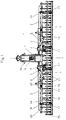
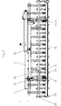
- FIG. 1 is in the embodiment shown here
- One attachment device 1 according to the invention of a manure spreader together with the manure spreader pipes 2 by means of hydraulic cylinders 3, on the one hand on a Frame 4 and the other on a connecting tube 5 of the Hitch 1 are pivotally attached on both sides a tower support 6 attached.
- Slurry distributor pipes 2 together with the attachment device 1 folded up and on both sides of the tower girder 6, which is connected to the slurry reservoir, at 6a locked.
- the position of the distributor pipes 2 shown in FIG. 1 corresponds the working position in the field.
- the hydraulic pistons 3 are extended and the manifolds 2 together with the attachment 1 along the rod 7 already been moved down.
- the height adjustment of the hitch 1 is selectable.
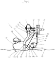
- FIG 4 shows an embodiment of the attachment device 1 together with the manifold 2 in side view partly in Section, separated from the frame 4 and its connection with the tower beam 6 shown.
- the slurry distributor pipe 2 is here as a pipe of about oval cross-section formed in the lower area there is a screw conveyor 8.
- the distribution pipe 2 are spaced from each other Outlet openings 9 with outlet nozzle 10, each on a hose 11 is attached, the end of which is in Working position of the manure spreader up to arable area 13 enough.
- the hose end 11a is surrounded by a sleeve 12, which gives the hose end 11a a certain stability, and the hose end 11a always in the immediate vicinity of the Surface of the field holds.
- the sleeve 12, as from Fig. 4 can be seen with a slide shoe 19 which in Cross-section has the shape of a U-profile, connected.
- the Slide shoe 19 is over ßlattfedern 20 with a horizontal Square support tube 21 of the attachment 1 connected. During the working process, the slide shoe 19 slides over the field and adapts due to its sprung attachment on the unevenness of the floor, but always keeps that Hose end 11a in the direction of the web and thus prevents lateral Swinging the hose end 11a back and forth.
- a scraper bar 14 is provided on the side of the hitch that is facing the tower girder 6 1.
- the length the scraper bar 14 extends beyond the length towards the outer end of the distributor pipe 2.
- the cross section of the scraper bar 14 4 has approximately the shape of a right triangle.
- the orientation of the one The surface belonging to cathode 14a is made by pivoting and screwing their retaining wing 15 to one Support plate 16 such that the scraper surface 14a approximately rests on the arable area 13, or slightly into it penetrates.
- the tip lying against the surface 14a Angle formed as an acute double corner 14b.
- the carrier plate 16 is height adjustable with two leaf springs 17 connected to a frame 18.
- One leg 19a of the U-profile 19 is so long trained that he arranged the height of the adjacent Scraper bar 14 towers over. The reason for this is that he itself in its up and down movements caused by the Bumps in the arable soil are caused, not in the Scraper bar can get caught.
- each between two neighboring ones A harrow tine 23 is provided on the hose ends 11a.
- Each Harrow tine 23 is on a leaf spring 24 on a square tube 25 attached, the square tube 25 in turn is again screwed in a height-adjustable manner in a support 26, which is pivotally held on a frame.
- This will achieved that the depth of penetration of the harrow tines 23 in the Soil 13 can be determined individually.
- a small depth of penetration is sufficient for this construction the harrow tines to get the desired result to obtain.
- a skid 14 formed a skid a tube 28 provided that the holding spring 27 with the leaf spring 17th connected is.
- other shapes to be used as a scraper if the desired one Function, namely lifting the layer of earth and its Transport over the surface of the scraper bar to the rear is achieved.
- a thin layer of earth is covered over the Pipe surface transported back to over again the manure penetrating into the ground to be thrown.
Landscapes
- Life Sciences & Earth Sciences (AREA)
- Soil Sciences (AREA)
- Engineering & Computer Science (AREA)
- Water Supply & Treatment (AREA)
- Environmental Sciences (AREA)
- Grinding-Machine Dressing And Accessory Apparatuses (AREA)
- Soil Working Implements (AREA)
Applications Claiming Priority (2)
| Application Number | Priority Date | Filing Date | Title |
|---|---|---|---|
| DE29712003U | 1997-07-08 | ||
| DE29712003U DE29712003U1 (de) | 1997-07-08 | 1997-07-08 | Vorrichtung für Güllevorratsbehälter |
Publications (1)
| Publication Number | Publication Date |
|---|---|
| EP0890300A1 true EP0890300A1 (fr) | 1999-01-13 |
Family
ID=8042804
Family Applications (1)
| Application Number | Title | Priority Date | Filing Date |
|---|---|---|---|
| EP98112564A Withdrawn EP0890300A1 (fr) | 1997-07-08 | 1998-07-07 | Appareil pour épandeur de purin |
Country Status (2)
| Country | Link |
|---|---|
| EP (1) | EP0890300A1 (fr) |
| DE (1) | DE29712003U1 (fr) |
Citations (4)
| Publication number | Priority date | Publication date | Assignee | Title |
|---|---|---|---|---|
| US3793967A (en) * | 1971-06-28 | 1974-02-26 | Lely Corp | Manure spreader |
| EP0266527A1 (fr) * | 1985-08-02 | 1988-05-11 | Amazonen-Werke H. Dreyer GmbH & Co. KG | Semoir |
| EP0548890A1 (fr) * | 1991-12-21 | 1993-06-30 | Konrad Hendlmeier | Méthode de semis direct et dispositif pour l'application de cette méthode |
| DE29715194U1 (de) * | 1997-08-23 | 1997-10-23 | Zunhammer, Sebastian, 83301 Traunreut | Vorrichtung zur Bodenbearbeitung |
Family Cites Families (3)
| Publication number | Priority date | Publication date | Assignee | Title |
|---|---|---|---|---|
| NL7712317A (nl) * | 1977-11-09 | 1979-05-11 | Patent Concern Nv | Grondbewerkingsmachine. |
| NL9401835A (nl) * | 1994-11-03 | 1995-12-01 | Gerard Johannes Schurink | Bemestingsinrichting. |
| DE29622584U1 (de) * | 1996-12-31 | 1997-02-20 | Eidelsburger, Hans, 86833 Ettringen | Flüssigkeits-Drillvorrichtung mit kombinierter Saatbettbestelltechnik |
-
1997
- 1997-07-08 DE DE29712003U patent/DE29712003U1/de not_active Expired - Lifetime
-
1998
- 1998-07-07 EP EP98112564A patent/EP0890300A1/fr not_active Withdrawn
Patent Citations (4)
| Publication number | Priority date | Publication date | Assignee | Title |
|---|---|---|---|---|
| US3793967A (en) * | 1971-06-28 | 1974-02-26 | Lely Corp | Manure spreader |
| EP0266527A1 (fr) * | 1985-08-02 | 1988-05-11 | Amazonen-Werke H. Dreyer GmbH & Co. KG | Semoir |
| EP0548890A1 (fr) * | 1991-12-21 | 1993-06-30 | Konrad Hendlmeier | Méthode de semis direct et dispositif pour l'application de cette méthode |
| DE29715194U1 (de) * | 1997-08-23 | 1997-10-23 | Zunhammer, Sebastian, 83301 Traunreut | Vorrichtung zur Bodenbearbeitung |
Also Published As
| Publication number | Publication date |
|---|---|
| DE29712003U1 (de) | 1997-10-02 |
Similar Documents
| Publication | Publication Date | Title |
|---|---|---|
| DE2140410C3 (de) | An ein ziehendes Fahrzeug anschließbare Sämaschine | |
| DE69813590T2 (de) | Pflanzeinheit | |
| DE2552810A1 (de) | Maschine zum ausbringen von saatgut und duengemitteln | |
| EP1477610B1 (fr) | Dispositif d'entretien de terrain d'équitation | |
| EP0289517B1 (fr) | Procede et dispositif d'ameublissement du sol | |
| DE3529517C2 (de) | Pflug | |
| DE2515767A1 (de) | Saatbeetaufbereitungsgeraet | |
| DE69102756T2 (de) | Injektionsvorrichtung für Flüssigdünger. | |
| DE3000959A1 (de) | Drillmaschine | |
| DE2528930A1 (de) | Tragrahmen fuer landwirtschaftliche maschinen und geraete | |
| DE3420617C2 (fr) | ||
| DE2010855C3 (de) | Maschine zum Ausbringen von Saatgut und Düngemitteln | |
| DE2742193A1 (de) | Verfahren und vorrichtung zum duengen von boeden | |
| DE3885929T2 (de) | Einrichtung zum Graben eines Tunnels. | |
| EP0890300A1 (fr) | Appareil pour épandeur de purin | |
| EP2628372A1 (fr) | Installation destinée au traitement agricole des sols en bandes | |
| DE69622813T2 (de) | Kreiselegge | |
| DE69910683T2 (de) | Sähmaschine | |
| DE8529225U1 (de) | Landwirtschaftliches Kombinationsgerät | |
| DE202021101060U1 (de) | Bodenbearbeitungsmaschine | |
| AT14597U1 (de) | Vorrichtung und Verfahren zur Bodenbearbeitung, -bewässerung und -aufbereitung | |
| DE19518301A1 (de) | Flüssigkeits- insbesondere Gülledrillvorrichtung | |
| DE3413517A1 (de) | Vorrichtung zur lockerung des untergrunds fuer landwirtschaftliche fahrzeuge und fahrbare geraete | |
| DE3707758A1 (de) | Saatbettkombination | |
| DE19832620A1 (de) | Vorrichtung zur mehrschichtigen Bodenbearbeitung |
Legal Events
| Date | Code | Title | Description |
|---|---|---|---|
| PUAI | Public reference made under article 153(3) epc to a published international application that has entered the european phase |
Free format text: ORIGINAL CODE: 0009012 |
|
| AK | Designated contracting states |
Kind code of ref document: A1 Designated state(s): AT CH DE DK FR GB LI NL |
|
| AX | Request for extension of the european patent |
Free format text: AL;LT;LV;MK;RO;SI |
|
| 17P | Request for examination filed |
Effective date: 19990616 |
|
| AKX | Designation fees paid |
Free format text: AT CH DE DK FR GB LI NL |
|
| STAA | Information on the status of an ep patent application or granted ep patent |
Free format text: STATUS: THE APPLICATION IS DEEMED TO BE WITHDRAWN |
|
| 18D | Application deemed to be withdrawn |
Effective date: 20000801 |