EP0890392A1 - Procédé et appareil d'opération d'un arrangement de buses - Google Patents
Procédé et appareil d'opération d'un arrangement de buses Download PDFInfo
- Publication number
- EP0890392A1 EP0890392A1 EP98112522A EP98112522A EP0890392A1 EP 0890392 A1 EP0890392 A1 EP 0890392A1 EP 98112522 A EP98112522 A EP 98112522A EP 98112522 A EP98112522 A EP 98112522A EP 0890392 A1 EP0890392 A1 EP 0890392A1
- Authority
- EP
- European Patent Office
- Prior art keywords
- nozzle
- liquid
- valve
- nozzles
- shut
- Prior art date
- Legal status (The legal status is an assumption and is not a legal conclusion. Google has not performed a legal analysis and makes no representation as to the accuracy of the status listed.)
- Withdrawn
Links
- 238000000034 method Methods 0.000 title claims description 19
- 239000000126 substance Substances 0.000 claims abstract description 22
- 239000007789 gas Substances 0.000 claims description 80
- 239000007788 liquid Substances 0.000 claims description 75
- XLYOFNOQVPJJNP-UHFFFAOYSA-N water Chemical compound O XLYOFNOQVPJJNP-UHFFFAOYSA-N 0.000 claims description 11
- 238000001816 cooling Methods 0.000 claims description 9
- IJGRMHOSHXDMSA-UHFFFAOYSA-N Atomic nitrogen Chemical compound N#N IJGRMHOSHXDMSA-UHFFFAOYSA-N 0.000 claims description 5
- 239000000203 mixture Substances 0.000 claims description 3
- 239000012530 fluid Substances 0.000 abstract description 9
- 229910000831 Steel Inorganic materials 0.000 description 4
- 239000010959 steel Substances 0.000 description 4
- 239000000428 dust Substances 0.000 description 3
- 230000000694 effects Effects 0.000 description 3
- 238000001704 evaporation Methods 0.000 description 3
- 239000003570 air Substances 0.000 description 2
- 230000015572 biosynthetic process Effects 0.000 description 2
- 230000005484 gravity Effects 0.000 description 2
- 238000002347 injection Methods 0.000 description 2
- 239000007924 injection Substances 0.000 description 2
- 229910052757 nitrogen Inorganic materials 0.000 description 2
- 239000007787 solid Substances 0.000 description 2
- 235000008733 Citrus aurantifolia Nutrition 0.000 description 1
- 235000011941 Tilia x europaea Nutrition 0.000 description 1
- 238000007664 blowing Methods 0.000 description 1
- 230000006866 deterioration Effects 0.000 description 1
- 239000004571 lime Substances 0.000 description 1
- 239000000463 material Substances 0.000 description 1
- 230000035515 penetration Effects 0.000 description 1
- 230000000630 rising effect Effects 0.000 description 1
- 239000000243 solution Substances 0.000 description 1
- 239000007921 spray Substances 0.000 description 1
Images
Classifications
-
- B—PERFORMING OPERATIONS; TRANSPORTING
- B01—PHYSICAL OR CHEMICAL PROCESSES OR APPARATUS IN GENERAL
- B01D—SEPARATION
- B01D53/00—Separation of gases or vapours; Recovering vapours of volatile solvents from gases; Chemical or biological purification of waste gases, e.g. engine exhaust gases, smoke, fumes, flue gases, aerosols
- B01D53/14—Separation of gases or vapours; Recovering vapours of volatile solvents from gases; Chemical or biological purification of waste gases, e.g. engine exhaust gases, smoke, fumes, flue gases, aerosols by absorption
- B01D53/18—Absorbing units; Liquid distributors therefor
- B01D53/185—Liquid distributors
-
- B—PERFORMING OPERATIONS; TRANSPORTING
- B05—SPRAYING OR ATOMISING IN GENERAL; APPLYING FLUENT MATERIALS TO SURFACES, IN GENERAL
- B05B—SPRAYING APPARATUS; ATOMISING APPARATUS; NOZZLES
- B05B12/00—Arrangements for controlling delivery; Arrangements for controlling the spray area
- B05B12/02—Arrangements for controlling delivery; Arrangements for controlling the spray area for controlling time, or sequence, of delivery
- B05B12/04—Arrangements for controlling delivery; Arrangements for controlling the spray area for controlling time, or sequence, of delivery for sequential operation or multiple outlets
-
- F—MECHANICAL ENGINEERING; LIGHTING; HEATING; WEAPONS; BLASTING
- F23—COMBUSTION APPARATUS; COMBUSTION PROCESSES
- F23J—REMOVAL OR TREATMENT OF COMBUSTION PRODUCTS OR COMBUSTION RESIDUES; FLUES
- F23J15/00—Arrangements of devices for treating smoke or fumes
- F23J15/06—Arrangements of devices for treating smoke or fumes of coolers
Definitions
- the invention relates to a method for operating an arrangement of one or more Nozzles or groups of nozzles, each nozzle or group of nozzles using a liquid medium Supply lines are supplied, and the liquid medium in a gas space for cooling this Gases is atomized and the liquid supply to each nozzle through a shut-off valve is lockable.
- the nozzles can be single-substance nozzles, for example high-pressure liquid nozzles, or Be two-substance nozzles, with the latter, each nozzle a gaseous medium, for example Air, nitrogen or water vapor, and a liquid medium, for example water separate feed lines are supplied.
- a gaseous medium for example Air, nitrogen or water vapor
- a liquid medium for example water separate feed lines are supplied.
- Nozzles operated in this way are used, for example, when cooling steel slabs, or also in the injection cooling of gas streams, as used for example when steel is freshly produced in a steel converter as converter exhaust gases.
- Nozzles or groups of nozzles arranged in a gas channel and connected in series.
- the gas generator for example the steel converter, can be adhered to a certain desired exhaust gas temperature may be required, a different one Number of nozzles, possibly none, to be operated simultaneously.
- the droplets generated by the nozzles should be as small as possible to make them large To achieve cooling effect. Larger drops are undesirable because these are due to the unfavorable ratio of surface to volume evaporate poorly and the Cooling effect is less. Larger drops are also not guaranteed to be in front Vaporize reaching the wall of the gas duct. The resulting local Temperature fluctuations can lead to tension, material fatigue and cracks in the Guide the wall of the gas duct. Furthermore, it is deposited on the always briefly moist Wall places dust from the gas to be cooled and forms caking, which with longer Operating time ultimately lead to a reduction in the cross section of the gas duct and have to be removed periodically in a complex manner.
- the object of the invention is therefore a method for improving the mode of operation to create an arrangement of nozzles or groups of nozzles, in which the listed Problems of the known methods can be avoided.
- the Decommissioning some of the nozzles or groups of nozzles the formation of deposits in the Nozzles and nozzle lances prevent liquid from flowing out of the Avoided liquid supply lines of shut-off nozzles and in the case of two-substance nozzles uninterrupted, continuous gas supply to the nozzles that are still in operation be ensured.
- the solution to this problem is characterized in that at Decommissioning a nozzle or nozzle group between the shut-off valve and nozzle in the Liquid supply remaining liquid against the normal flow direction of the Liquid is removed.
- the invention relates to both the method according to the invention and Devices for performing the method.
- Two-component nozzles are usually made with gases that are readily available for the respective application and liquids operated.
- gases that are readily available for the respective application and liquids operated.
- a gas that is usually compressed air nitrogen or water vapor are preferably used.
- the liquid is preferably water, namely ordinary service water with a concentration of dissolved solids of, for example, about 0.1 g / liter. This However, value can vary considerably due to geographically different water hardness vary.
- the decommissioning of a nozzle or nozzle group is advantageously carried out by closing the liquid supply line and simultaneously or immediately afterwards the Liquid drain is opened. This allows between in the liquid supply line The shut-off valve and nozzle drain any remaining liquid due to gravity alone.
- the gas feed line advantageously communicates with a compressed gas storage tank, which after turning off the gas supply line in during normal operation gas stored inside helps to blow out the liquid.
- Another advantageous process feature is that the gas supply line after the Decommissioning the two-fluid nozzle is constantly flushed with a small amount of gas. This prevents dust from the hot gas from entering the gas channel into the nozzle penetrates and pollutes them.
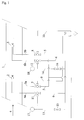
- Fig. 1 shows schematically an arrangement of two two-substance nozzles or Two-component nozzle groups with their gas and liquid supply.
- the two-substance nozzles 2, 3 are arranged in a gas channel in a cascaded circuit.
- the two-substance nozzles 2, 3 can each consist of a single nozzle or of one Group of three nozzles, for example.
- the flow direction of the hot to be cooled Exhaust gas is indicated by arrow 4.
- the nozzles 2, 3 are liquid via a line 5 fed.
- the gas with which the liquid is atomized is sent to the nozzles 2, 3 via line 6 fed.
- the valves 7 and 8 are designed as multi-way valves and are in operation of both Two-substance nozzles 2, 3 switched so that the liquid from line 5 in line 5a to nozzle 2, or can flow from line 5 in line 5b to the nozzle 3.
- the valves are in normal operation 7 and 8 also switched so that no liquid through the leads 9 and 10th can drain off.
- the valves 11 and 12 are also designed as multi-way valves and at Normal operation of both two-substance nozzles 2, 3 switched such that gas lines 6 and 6a, and 6th and 6b are openly connected, but not that of the valves 11 and 12 from the gas supply line 6 branching lines 13 and 14.
- lines 13 and 14 in which only one through Throttles 15 and 16 low gas flow can flow are Pressurized gas storage containers 17 and 18. These communicate during normal operation correspondingly reduced pressure with the gas supply line 6.
- valve 8 is switched in such a way that the liquid flow from 5 to 5b is prevented and the liquid can flow off via drain 10.
- Valve 12 will switched simultaneously with valve 8 so that the gas flow from 6 to 6b is prevented and the compressed gas storage container 18 is now open according to FIG. 6b. That in the compressed gas storage tank 18 stored gas presses together with the gas still remaining in line 6b Nozzle 3, the liquid remaining in line 5b backwards, ie contrary to the normal one Flow direction, beyond line 10. In this position of valve 12 is also Connection from line 14 to line 6b open.
- a throttle 16 can be small held gas flow, flush the gas supply line 6b and nozzle 3, thereby preventing this Penetration of dust from the exhaust gas flow into nozzle 3.
- nozzles or groups of nozzles can be cascaded Circuit be arranged.
- each of the nozzles or nozzle groups separately switched on or off by the method according to the invention become.
Landscapes
- Engineering & Computer Science (AREA)
- Chemical & Material Sciences (AREA)
- Mechanical Engineering (AREA)
- General Engineering & Computer Science (AREA)
- Analytical Chemistry (AREA)
- General Chemical & Material Sciences (AREA)
- Oil, Petroleum & Natural Gas (AREA)
- Chemical Kinetics & Catalysis (AREA)
- Nozzles (AREA)
Applications Claiming Priority (2)
| Application Number | Priority Date | Filing Date | Title |
|---|---|---|---|
| AT1184/97 | 1997-07-10 | ||
| AT0118497A AT405144B (de) | 1997-07-10 | 1997-07-10 | Verfahren und vorrichtung für den betrieb von düsen |
Publications (1)
| Publication Number | Publication Date |
|---|---|
| EP0890392A1 true EP0890392A1 (fr) | 1999-01-13 |
Family
ID=3508428
Family Applications (1)
| Application Number | Title | Priority Date | Filing Date |
|---|---|---|---|
| EP98112522A Withdrawn EP0890392A1 (fr) | 1997-07-10 | 1998-07-07 | Procédé et appareil d'opération d'un arrangement de buses |
Country Status (2)
| Country | Link |
|---|---|
| EP (1) | EP0890392A1 (fr) |
| AT (1) | AT405144B (fr) |
Cited By (2)
| Publication number | Priority date | Publication date | Assignee | Title |
|---|---|---|---|---|
| DE10251082A1 (de) * | 2002-11-02 | 2004-05-13 | Heinz Karle | Vorrichtung und Verfahren zur Erzeugung eines Flüssigkeit-Gas-Gemisches, insbesondere eines Aerosols |
| DE102010051339A1 (de) * | 2010-11-13 | 2012-05-16 | Ingo Grausam | Vorrichtung zur Erzeugung eines Aerosols |
Citations (6)
| Publication number | Priority date | Publication date | Assignee | Title |
|---|---|---|---|---|
| JPS6391162A (ja) * | 1986-10-02 | 1988-04-21 | Mazda Motor Corp | 塗装方法およびその装置 |
| JPH034951A (ja) * | 1989-05-30 | 1991-01-10 | Oogawara Kakoki Kk | 2流体噴霧ノズル機構 |
| US5074226A (en) * | 1991-02-15 | 1991-12-24 | Field Service Associates, Inc. | Flue gas conditioning system |
| JPH06304503A (ja) * | 1993-04-27 | 1994-11-01 | Toyota Motor Corp | 塗料の色替え装置と色替え方法 |
| WO1995025931A1 (fr) * | 1994-03-21 | 1995-09-28 | Techform Engineering Ag | Procede et dispositif d'introduction d'un milieu de conditionnement en phase liquide ou gazeuse dans un courant de gaz de fumee |
| WO1996008639A1 (fr) * | 1994-09-13 | 1996-03-21 | Siemens Aktiengesellschaft | Procede et systeme permettant d'introduire un fluide dans une dispositif d'epuration de gaz d'echappement |
-
1997
- 1997-07-10 AT AT0118497A patent/AT405144B/de not_active IP Right Cessation
-
1998
- 1998-07-07 EP EP98112522A patent/EP0890392A1/fr not_active Withdrawn
Patent Citations (6)
| Publication number | Priority date | Publication date | Assignee | Title |
|---|---|---|---|---|
| JPS6391162A (ja) * | 1986-10-02 | 1988-04-21 | Mazda Motor Corp | 塗装方法およびその装置 |
| JPH034951A (ja) * | 1989-05-30 | 1991-01-10 | Oogawara Kakoki Kk | 2流体噴霧ノズル機構 |
| US5074226A (en) * | 1991-02-15 | 1991-12-24 | Field Service Associates, Inc. | Flue gas conditioning system |
| JPH06304503A (ja) * | 1993-04-27 | 1994-11-01 | Toyota Motor Corp | 塗料の色替え装置と色替え方法 |
| WO1995025931A1 (fr) * | 1994-03-21 | 1995-09-28 | Techform Engineering Ag | Procede et dispositif d'introduction d'un milieu de conditionnement en phase liquide ou gazeuse dans un courant de gaz de fumee |
| WO1996008639A1 (fr) * | 1994-09-13 | 1996-03-21 | Siemens Aktiengesellschaft | Procede et systeme permettant d'introduire un fluide dans une dispositif d'epuration de gaz d'echappement |
Non-Patent Citations (3)
| Title |
|---|
| PATENT ABSTRACTS OF JAPAN vol. 012, no. 326 (C - 525) 5 September 1988 (1988-09-05) * |
| PATENT ABSTRACTS OF JAPAN vol. 015, no. 112 (C - 0815) 18 March 1991 (1991-03-18) * |
| PATENT ABSTRACTS OF JAPAN vol. 095, no. 002 31 March 1995 (1995-03-31) * |
Cited By (2)
| Publication number | Priority date | Publication date | Assignee | Title |
|---|---|---|---|---|
| DE10251082A1 (de) * | 2002-11-02 | 2004-05-13 | Heinz Karle | Vorrichtung und Verfahren zur Erzeugung eines Flüssigkeit-Gas-Gemisches, insbesondere eines Aerosols |
| DE102010051339A1 (de) * | 2010-11-13 | 2012-05-16 | Ingo Grausam | Vorrichtung zur Erzeugung eines Aerosols |
Also Published As
| Publication number | Publication date |
|---|---|
| AT405144B (de) | 1999-05-25 |
| ATA118497A (de) | 1998-10-15 |
Similar Documents
| Publication | Publication Date | Title |
|---|---|---|
| DE3728557C2 (fr) | ||
| DE2338102A1 (de) | Vorrichtung zur tropfenerzeugung und verfahren zu ihrem betrieb | |
| DE3131070A1 (de) | "spruehduese mit hohem wirkungsgrad" | |
| EP0090090A2 (fr) | Procédé pour le nettoyage des cavités de soupapes à double siège | |
| CH682982A5 (de) | Apparat zur Aufwärmung und Entgasung von Wasser. | |
| DE2350678C3 (de) | Vorrichtung zur Abgabe eines flüssigen Kryogenen Kälteträgers | |
| WO2004053023A1 (fr) | Appareil de refroidissement pour gaz de four a coke | |
| DE3339930A1 (de) | Verfahren und vorrichtung zum sterilisieren von zur aufnahme von molkereiprodukten bestimmter becherfoermiger behaelter | |
| EP0215230A1 (fr) | Dispositif de dégazage de condensat dans le circuit d'une unité de production d'électricité | |
| AT405144B (de) | Verfahren und vorrichtung für den betrieb von düsen | |
| EP3717139B1 (fr) | Dispositif et procédé pour l'odorisation d'un flux gazeux dans une conduite de gaz | |
| EP3335812A1 (fr) | Installation de refroidissement de laminés | |
| EP1091050A1 (fr) | Procéder et dispositif pour dégager d'eau carbonisé sur un robinet | |
| EP1073531B1 (fr) | Dispositif et procede de lavage alterne sous pression | |
| DE2440415C2 (fr) | ||
| EP1142611B1 (fr) | Procédé pour l'optimisation d'un système d'extinction d'incendie à pulvérisation d'eau et système d'extinction d'incendie à pulvérisation d'eau pour la mise en oeuvre du procédé | |
| DE2359189A1 (de) | Vorrichtung zum verspruehen eines spruehmediums | |
| EP3387236B1 (fr) | Turbine à gaz dotée d'un dispositif de compression en régime humide pour introduire un mélange liquide tensioactif | |
| DE69132990T2 (de) | Reinigungsgerät | |
| DE69418226T2 (de) | Verfahren zum Trocknen bedruckter Streifen | |
| DE102022210720A1 (de) | Verfahren zum Berieseln eines Wärmeübertragers | |
| EP1085264A1 (fr) | Procédé et dispositif pour le refroidissement par eau d'une grille de combustion | |
| DE2611454A1 (de) | Abtreibkolonne | |
| DE3809473A1 (de) | Reinigungseinrichtung in anlagen fuer die synthese von chemischen verbindungen, die reinigungseinrichtung enthaltende anlage und verfahren zur reinigung der letzteren | |
| DE1918972A1 (de) | Vorrichtung und Verfahren zum Bespritzen von Gegenstaenden mit viskosen Fluessigkeiten |
Legal Events
| Date | Code | Title | Description |
|---|---|---|---|
| PUAI | Public reference made under article 153(3) epc to a published international application that has entered the european phase |
Free format text: ORIGINAL CODE: 0009012 |
|
| AK | Designated contracting states |
Kind code of ref document: A1 Designated state(s): BE CH DE ES FR GB IT LI |
|
| AX | Request for extension of the european patent |
Free format text: AL;LT;LV;MK;RO;SI |
|
| 17P | Request for examination filed |
Effective date: 19990423 |
|
| AKX | Designation fees paid |
Free format text: BE CH DE ES FR GB IT LI |
|
| STAA | Information on the status of an ep patent application or granted ep patent |
Free format text: STATUS: THE APPLICATION IS DEEMED TO BE WITHDRAWN |
|
| 18D | Application deemed to be withdrawn |
Effective date: 20030201 |