EP0890687A2 - Procédé de fabrication d' un closoir de faitage - Google Patents
Procédé de fabrication d' un closoir de faitage Download PDFInfo
- Publication number
- EP0890687A2 EP0890687A2 EP98111091A EP98111091A EP0890687A2 EP 0890687 A2 EP0890687 A2 EP 0890687A2 EP 98111091 A EP98111091 A EP 98111091A EP 98111091 A EP98111091 A EP 98111091A EP 0890687 A2 EP0890687 A2 EP 0890687A2
- Authority
- EP
- European Patent Office
- Prior art keywords
- cutting tools
- metal strip
- strip
- ventilation
- ridge
- Prior art date
- Legal status (The legal status is an assumption and is not a legal conclusion. Google has not performed a legal analysis and makes no representation as to the accuracy of the status listed.)
- Granted
Links
Images

Classifications
-
- E—FIXED CONSTRUCTIONS
- E04—BUILDING
- E04D—ROOF COVERINGS; SKY-LIGHTS; GUTTERS; ROOF-WORKING TOOLS
- E04D1/00—Roof covering by making use of tiles, slates, shingles, or other small roofing elements
- E04D1/36—Devices for sealing the spaces or joints between roof-covering elements
-
- E—FIXED CONSTRUCTIONS
- E04—BUILDING
- E04D—ROOF COVERINGS; SKY-LIGHTS; GUTTERS; ROOF-WORKING TOOLS
- E04D13/00—Special arrangements or devices in connection with roof coverings; Protection against birds; Roof drainage ; Sky-lights
- E04D13/17—Ventilation of roof coverings not otherwise provided for
- E04D13/174—Ventilation of roof coverings not otherwise provided for on the ridge of the roof
- E04D13/176—Ventilation of roof coverings not otherwise provided for on the ridge of the roof formed by flexible material suitable to be rolled up
Definitions
- the invention relates to a process for the continuous production of corrugated, metallic Ridge and ridge sealing strips, the one to be placed on the ridge or ridge slat Median strips, perforated ventilation strips and have adjoining edge strips by a metal strip from a reel subtracted and between two transverse to the direction of travel over at least the width of the metal strip extending form rollers for molding the shafts and the metal strip in the area of the ventilation strips by means of multiple tools with a large number of ventilation openings of small cross-section are
- Ridge and ridge sealing strips of the aforementioned type are rolled up on site used. Before the cover caps of the roof covering are put on, the roller is attached placed on the median strip on the ridge or ridge battens and along them unrolled.
- the ventilation strips adjoining the median strips serve on both sides with their perforation for ventilation of the roof space and are with their edge strips that are provided with traces of adhesive, attached to the roof panels.
- the perforation should be designed so that that flying snow and water cannot penetrate into the attic.
- ridge and ridge sealing strips are particularly advantageous Metal, e.g. Aluminum, copper, zinc, lead or the like, which are absolutely weatherproof and have a long service life.
- Such sealing strips have also been found proven, which are corrugated or pleated transverse to their longitudinal extent.
- Ridge and ridge sealing strips made of metal have so far been produced in such a way that the metal tape housed on a reel is peeled off and initially by means of the ventilation openings in the two ventilation strips be punched out. Then it goes through with the ventilation openings
- Metal band provided a pair of form rollers which form the shaft. After that traces of adhesive are applied along the edge strips and these are then applied by a peelable strip material, e.g. a strip of paper, covered. Finally the metal strip assembled in this way is wound on a spool.
- the object of the invention is the method mentioned at the beginning further develop performance and propose a device that with much higher performance than the known device works.
- the object is achieved in that in the running direction the metal band through the ventilation openings after shaping the shaft machining of the wave crests, in particular by means of rotating Cutting tools such as saws or milling cutters are manufactured.
- a large number of disk-shaped cutting tools are known today work at high speeds with a long service life. Allow such cutting tools in connection with the measure, the ventilation openings in the area of the wave crests in a continuous process to produce a high working speed that is almost in the area of the working speed during plastic forming using the forming rollers lies.
- the performance can at least tripled. This results in a reduction in manufacturing costs and compared the separate way of working reduces the set-up, working and handling times.
- the entire production takes place in a single pass from the raw material to the end product.
- the functional reliability compared to punching is included the heavily used and therefore often failing stamps elevated. Downtime is reduced by around 90%.
- the ventilation openings are in the form of slots educated. This shape allows the formation of relatively large cross sections Compliance with the roof ventilation regulations according to DIN 4108, paragraph 3, at the same time narrow slot width, what the tightness against flying snow and driving rain (Surface tension) is significant.
- the ventilation holes can be cut by machining or by Counter-rotating machining can be produced.
- the ventilation holes are parallel Saw cuts generated.
- the invention proceeds from a known device consisting of a device for feeding a Metal strip, for example a reel with the wound metal strip, and a pair of intermeshing arranged behind it in the running direction Forming rollers for shaping the shafts and with at least two groups of There are multiple tools for machining the ventilation openings.
- This known device is further developed according to the invention in that the two groups of multiple tools in the running direction behind the form rollers are arranged and consist of revolving cutting tool sets, which with respect of the incoming, corrugated band are arranged at such a height that they remove one or more chips from the wave crests with a thickness that is at least little is greater than the tape thickness.
- the device according to the invention thus works in a continuous process with a Molding station with the forming rollers and a processing station with the cutting tools.
- the individual cutting tools of the Tool sets each create a cut on the wave crests, the Depth of cut is greater than the band thickness, so that an opening is formed.
- Their breadth is determined by the width of the cutting tools, while their length is from the Infeed or the immersion depth in the wave crests.
- the possible stretchability of the metal strip depends on the wave height Longitudinal direction, i.e. the adaptability to roof tiles.
- a larger wave height of the metal strip of, for example, 5 mm is necessary at slightly corrugated roof tiles can have a corrugation height of the metal band
- 1.5 mm is sufficient, a good intermediate value is allowed
- the wave height of the metal strip must be 3 mm.
- the rotating cutting tools are preferably in relation to the incoming, corrugated band so far that in the area of the crests Slit-like ventilation openings extending in the direction of travel are created.
- the slot length is determined exclusively by the delivery of the cutting tools can also be varied if necessary.
- the cutting wheels can be used as circular saw blades, disc milling cutters or as clearing wheels be trained. The selection depends, among other things, on the desired one Working speed, punching time and the metal material to be processed.
- the two are expediently next to one another transversely to the running direction arranged groups of cutting tools on a common drive shaft arranged, this drive shaft with that of the second group via a Reverse drive can be driven synchronously with speed.
- a counter-pressure roller is assigned which the metal strip in the area between supports the cutting tools.
- This counter-pressure roller can, for example have grooves around their circumference relative to the cutting tools.
- the counter-pressure roller which may also be formed in two parts and one each Cutting tool groups assigned can also serve as a transport roller. She is then advantageously driven synchronously with the forming rollers, while the Cutting tools at least the first group driven at a higher speed are.
- each group consists of ten to eighteen Cutting tools so that each ventilation strip is parallel with ten to eighteen Rows of ventilation slots is provided.
- the cutting width of the cutting tools is preferably between 0.5 and 1.5 mm, which in turn determines the slot width.
- the slot length can be adjusted in that the cutting tools with respect to the Metal strip are adjustable so far that the ventilation slots generated a length have from 1.0 to 4.5 mm.
- the Forming rollers at the transitions from the central strip to the two ventilation strips Beading profiles for inserting at least two longitudinal bending beads has, the forming roller preferably on both sides of the central strip has at least two spaced bead profiles.
- the form rollers are exchangeable on the drive shaft arranged so that they can be replaced when worn or with form rollers another profile can be exchanged.
- the cutting tool sets preferably consist of sets arranged in sets Tool disks that can be replaced individually or in groups on their drive shaft are arranged. This means that individual tool disks can become worn exchanged or the entire tool disc set for a set of others Working width can be replaced.
- the counter-pressure roller can also be replaced on its drive shaft be exchangeable for counter pressure rollers with a different spacing of the circumferential grooves.
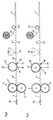
- the metal band is on at its longitudinal edges Shoes 23, 23 'guided on an adjusting spindle 24 to vary the bandwidth are stored. Such guide shoes can be along the running direction of the belt be arranged in several places.
- the incoming metal strip 1 becomes a ridge and Burr sealing strip I 'made with the transverse to its longitudinal extent a wave profile 11 is provided. It has a median strip 7 for resting on the Ridge lath on. On both sides of the median strip 7 there are two at a distance from one another Bending beads 3, 4 or 3 ', 4' arranged, which have a tolerance range 8, 8 'between them leave to allow adaptation to ridge battens of different widths.
- the incoming metal strip 1 first passes between two forming rolls 2, 2 ' circulate synchronously and also serve as transport rollers. They point to theirs Sheath an axially parallel, gear-like profile, by means of which the shafts 11 in the Metal sheet can be molded. Both sides of the center strip 7 have the shape roll 2, 2 'bead profiles 5, 6 or 5', 6 'onto the bending beads 3, 4 or 3', 4 ' mold.
- the ventilation openings 12 'in the form of slots by machining produce In the running direction behind the forming rolls 2, 2 'are - in the embodiment shown below the corrugated metal band - two groups of rotating ones Cutting tools 15, 15 'arranged on a common drive shaft 14, the ventilation openings 12 'in the form of slots by machining produce.
- the cutting tools only attack in the area of the wave crests, the slot length being determined by the feed path of the cutting tools 15, 15 ' can vary.
- the width of the vents 12 is determined by the width of the individual Cutting tool determined.
- the first group of cutting tools 15, 15 ' is a counter pressure roller 27 assigned, whose profile 28 (FIG. 4) essentially that of the shaping rolls 2, 2 ' corresponds and which is driven synchronously with the forming rollers. With this profile the wave crests are supported between the cutting tools.
- the platen 27 In the field of Cutting tools themselves is the platen 27 either shortened Provide profile height 29 (Fig. 3) or circumferential grooves into which the cutting tools 15, 15 ' can intervene.
- the disk-shaped tools 15, 15 'and 17, 17' of the two groups of Cutting tool sets can be used as circular saw blades, disc cutters or Be clearing discs.
- 2 shows, the cutting tool 15 work, 15 'of the first group in the opposite direction by the drive shaft 14 against the Direction of rotation of the metal strip rotates while the cutting tools 17, 17 ' work in sync with the two groups behind. That way the burrs 13 formed during processing by the first group from the second Removed group of cutting tools so that burr-free, slit-like Ventilation openings 12, 12 'can be obtained.
- the adhesive is made from the cassettes in the form of an adhesive track 20, 21 submitted.
Landscapes
- Architecture (AREA)
- Civil Engineering (AREA)
- Structural Engineering (AREA)
- Engineering & Computer Science (AREA)
- Bending Of Plates, Rods, And Pipes (AREA)
- Roof Covering Using Slabs Or Stiff Sheets (AREA)
- Perforating, Stamping-Out Or Severing By Means Other Than Cutting (AREA)
- Metal Rolling (AREA)
- Gasket Seals (AREA)
- Making Paper Articles (AREA)
- Packages (AREA)
- Basic Packing Technique (AREA)
- Duct Arrangements (AREA)
- Folding Of Thin Sheet-Like Materials, Special Discharging Devices, And Others (AREA)
- Testing Of Coins (AREA)
- Soil Working Implements (AREA)
- Semiconductor Lasers (AREA)
- Sealing Battery Cases Or Jackets (AREA)
- Nonmetallic Welding Materials (AREA)
- Milling Processes (AREA)
- Sealing Material Composition (AREA)
Priority Applications (1)
| Application Number | Priority Date | Filing Date | Title |
|---|---|---|---|
| SI9830544T SI0890687T1 (en) | 1997-07-10 | 1998-06-17 | Method of making a roof ridge strip |
Applications Claiming Priority (2)
| Application Number | Priority Date | Filing Date | Title |
|---|---|---|---|
| DE19729504A DE19729504A1 (de) | 1997-07-10 | 1997-07-10 | Verfahren zur Herstellung von Frist- und Gratabdichtungsstreifen |
| DE19729504 | 1997-07-10 |
Publications (3)
| Publication Number | Publication Date |
|---|---|
| EP0890687A2 true EP0890687A2 (fr) | 1999-01-13 |
| EP0890687A3 EP0890687A3 (fr) | 2000-02-23 |
| EP0890687B1 EP0890687B1 (fr) | 2003-08-06 |
Family
ID=7835242
Family Applications (1)
| Application Number | Title | Priority Date | Filing Date |
|---|---|---|---|
| EP98111091A Expired - Lifetime EP0890687B1 (fr) | 1997-07-10 | 1998-06-17 | Procédé de fabrication d' un closoir de faitage |
Country Status (9)
| Country | Link |
|---|---|
| EP (1) | EP0890687B1 (fr) |
| AT (1) | ATE246758T1 (fr) |
| CZ (1) | CZ297420B6 (fr) |
| DE (2) | DE19729504A1 (fr) |
| DK (1) | DK0890687T3 (fr) |
| HU (1) | HU219970B (fr) |
| PL (1) | PL186788B1 (fr) |
| SI (1) | SI0890687T1 (fr) |
| SK (1) | SK284685B6 (fr) |
Cited By (2)
| Publication number | Priority date | Publication date | Assignee | Title |
|---|---|---|---|---|
| EP1508655A1 (fr) * | 2003-08-21 | 2005-02-23 | Peter Wirz | Bande de matériau en forme de ruban, pour faíte ou arête de couverture |
| DE202005000616U1 (de) * | 2005-01-15 | 2006-02-02 | Bts Bautechnischesysteme Gmbh & Co. Kg | Rollbares First-Entlüftungsband |
Families Citing this family (2)
| Publication number | Priority date | Publication date | Assignee | Title |
|---|---|---|---|---|
| DE19912698A1 (de) * | 1999-03-20 | 2000-09-21 | Manfred Gehring | Vorrichtung und Verfahren zur Herstellung eines First- und Gratabdeckungsstreifens aus einem Streifen aus plastisch verformbaren Material |
| DE102006009569B3 (de) * | 2006-02-28 | 2007-02-15 | Daimlerchrysler Ag | Vorrichtung und Verfahren zum Beschneiden von blechförmigem Material oder eines blechförmigen Bauteils |
Family Cites Families (4)
| Publication number | Priority date | Publication date | Assignee | Title |
|---|---|---|---|---|
| US2250593A (en) * | 1939-06-16 | 1941-07-29 | Mesnel Pierre | Method and machine for cutting openings in metal ribbons or the like |
| JPS5691931A (en) * | 1979-12-27 | 1981-07-25 | Toyoda Gosei Co Ltd | Production of trim core material |
| US4886711A (en) * | 1987-11-27 | 1989-12-12 | General Motors Corporation | Catalytic converter metal monolithic catalyst substrate |
| DE29501242U1 (de) * | 1995-01-27 | 1995-03-16 | Gehring Manfred Dr | Rollbarer Dichtungsstreifen für eine First- und/oder Gratabdeckung |
-
1997
- 1997-07-10 DE DE19729504A patent/DE19729504A1/de not_active Withdrawn
-
1998
- 1998-06-17 DE DE59809181T patent/DE59809181D1/de not_active Expired - Lifetime
- 1998-06-17 SI SI9830544T patent/SI0890687T1/xx unknown
- 1998-06-17 DK DK98111091T patent/DK0890687T3/da active
- 1998-06-17 EP EP98111091A patent/EP0890687B1/fr not_active Expired - Lifetime
- 1998-06-17 AT AT98111091T patent/ATE246758T1/de active
- 1998-06-29 SK SK902-98A patent/SK284685B6/sk not_active IP Right Cessation
- 1998-06-29 PL PL98327102A patent/PL186788B1/pl unknown
- 1998-07-02 HU HU9801500A patent/HU219970B/hu not_active IP Right Cessation
- 1998-07-03 CZ CZ0214198A patent/CZ297420B6/cs not_active IP Right Cessation
Cited By (2)
| Publication number | Priority date | Publication date | Assignee | Title |
|---|---|---|---|---|
| EP1508655A1 (fr) * | 2003-08-21 | 2005-02-23 | Peter Wirz | Bande de matériau en forme de ruban, pour faíte ou arête de couverture |
| DE202005000616U1 (de) * | 2005-01-15 | 2006-02-02 | Bts Bautechnischesysteme Gmbh & Co. Kg | Rollbares First-Entlüftungsband |
Also Published As
| Publication number | Publication date |
|---|---|
| HUP9801500A1 (hu) | 1999-06-28 |
| CZ297420B6 (cs) | 2006-12-13 |
| PL186788B1 (pl) | 2004-02-27 |
| DE19729504A1 (de) | 1999-01-14 |
| EP0890687A3 (fr) | 2000-02-23 |
| DE59809181D1 (de) | 2003-09-11 |
| PL327102A1 (en) | 1999-01-18 |
| HU219970B (hu) | 2001-10-28 |
| SK284685B6 (sk) | 2005-09-08 |
| CZ214198A3 (cs) | 1999-08-11 |
| HU9801500D0 (en) | 1998-08-28 |
| ATE246758T1 (de) | 2003-08-15 |
| SI0890687T1 (en) | 2004-02-29 |
| SK90298A3 (en) | 1999-02-11 |
| DK0890687T3 (da) | 2003-11-24 |
| EP0890687B1 (fr) | 2003-08-06 |
Similar Documents
| Publication | Publication Date | Title |
|---|---|---|
| DE4400185B4 (de) | Verfahren und Vorrichtung zur Herstellung einer zwei Flansche und einen Steg aufweisenden Schiene für Hängedecken | |
| DE3814448C2 (fr) | ||
| DE2705167C2 (fr) | ||
| EP3278967A1 (fr) | Procédé et dispositif de fabrication d'une bande d'étanchéité et bande d'étanchéité avec un support de base | |
| DE3140630C2 (de) | Spikeplatte und Verfahren zur Herstellung sowie Einrichtung zum Zähnen von Spikeplatten | |
| DE2343579A1 (de) | Verfahren und vorrichtung zur formung eines metallstreifens mit laengs seiner breite unterschiedlicher dicke | |
| CH631094A5 (en) | Method and apparatus for the production of composite profiles by extrusion | |
| EP0890687B1 (fr) | Procédé de fabrication d' un closoir de faitage | |
| DE202008013876U1 (de) | Vorrichtung zum Rollformen von Blech | |
| EP0492428A2 (fr) | Dispositif pour poinçonner des pentures en feuilles ou en tôles | |
| CH435183A (de) | Verfahren und Vorrichtung zur Herstellung profilierter, geschweisster Längsträger, sowie nach dem Verfahren hergestellter Stahlleichtträger | |
| DE69527138T2 (de) | Rasierklingenherstellung | |
| DE69106593T2 (de) | Metallische Armierung für Dichtungsband oder dergleichen und Verfahren zu seiner Herstellung. | |
| DE2359368A1 (de) | Verfahren und vorrichtung zur herstellung von verstaerkungselementen kurzer laengenausdehnung | |
| EP1039063B1 (fr) | Dispositif et procédé de fabrication d'une bande pour le recouvrement des faîtes et des arêtes de toits, à partir d'une bande en matériau déformable plastiquement | |
| EP1964621B1 (fr) | Dispositif et procédé de fabrication de profilés | |
| DE10211257B4 (de) | Verfahren zum mechanischen Verbinden von zwei Elementen aus Metall, bei welchem die beiden Elemente aus Metall zwischen einem einzigen Satz von zwei Walzen hindurchgeführt werden | |
| DE10027010C2 (de) | Verfahren zur Herstellung eines Streckgitters sowie ein mit diesem Verfahren hergestelltes Streckgitter | |
| EP1949980B1 (fr) | Procédé et dispositif de fabrication d'une bande crêpée pour des éléments de connection et de jonction pour bâtiments | |
| DE60204888T2 (de) | Rotierendes standwerkzeug zum kontinuierlischen lochen von profilen sowie verwendung desselben | |
| EP2565357A2 (fr) | Procédé et dispositif de traitement d'une bande plastique lors de la fabrication d'un écarteur en forme de cadre pour des vitres isolantes | |
| DE2103616A1 (de) | Blech mit aufblasbaren Kanalbereichen sowie Verfahren und Vorrichtung zum Schneiden eines solchen Bleches in Streifen | |
| AT406129B (de) | Vorrichtung zum spanabhebenden bearbeiten einer streifenförmigen werkstückfläche | |
| AT390751B (de) | Verfahren und vorrichtung zum bearbeiten der kanten von blechen | |
| DE508847C (de) | Verfahren zur Herstellung von daubenartigen und aehnlichen Arbeitsstuecken fuer Faesser, Kuebel o. dgl. aus einem Rohmaterialstreifen von Fasermaterial |
Legal Events
| Date | Code | Title | Description |
|---|---|---|---|
| PUAI | Public reference made under article 153(3) epc to a published international application that has entered the european phase |
Free format text: ORIGINAL CODE: 0009012 |
|
| AK | Designated contracting states |
Kind code of ref document: A2 Designated state(s): AT BE CH CY DE DK ES FI FR GB GR IE IT LI LU NL PT SE |
|
| AX | Request for extension of the european patent |
Free format text: AL;LT;LV;MK;RO;SI |
|
| PUAL | Search report despatched |
Free format text: ORIGINAL CODE: 0009013 |
|
| AK | Designated contracting states |
Kind code of ref document: A3 Designated state(s): AT BE CH CY DE DK ES FI FR GB GR IE IT LI LU MC NL PT SE |
|
| AX | Request for extension of the european patent |
Free format text: AL;LT;LV;MK;RO;SI |
|
| RIC1 | Information provided on ipc code assigned before grant |
Free format text: 7E 04D 1/36 A, 7E 04D 13/16 B, 7B 21D 31/04 B |
|
| 17P | Request for examination filed |
Effective date: 20000525 |
|
| AKX | Designation fees paid |
Free format text: AT BE CH CY DE DK ES FI FR GB GR IE IT LI LU NL PT SE |
|
| AXX | Extension fees paid |
Free format text: AL PAYMENT 20000525;LT PAYMENT 20000525;LV PAYMENT 20000525;MK PAYMENT 20000525;RO PAYMENT 20000525;SI PAYMENT 20000525 |
|
| GRAH | Despatch of communication of intention to grant a patent |
Free format text: ORIGINAL CODE: EPIDOS IGRA |
|
| GRAH | Despatch of communication of intention to grant a patent |
Free format text: ORIGINAL CODE: EPIDOS IGRA |
|
| GRAA | (expected) grant |
Free format text: ORIGINAL CODE: 0009210 |
|
| AK | Designated contracting states |
Designated state(s): AT BE CH CY DE DK ES FI FR GB GR IE IT LI LU NL PT SE |
|
| AX | Request for extension of the european patent |
Extension state: AL LT LV MK RO SI |
|
| PG25 | Lapsed in a contracting state [announced via postgrant information from national office to epo] |
Ref country code: IE Free format text: LAPSE BECAUSE OF FAILURE TO SUBMIT A TRANSLATION OF THE DESCRIPTION OR TO PAY THE FEE WITHIN THE PRESCRIBED TIME-LIMIT Effective date: 20030806 Ref country code: GB Free format text: LAPSE BECAUSE OF FAILURE TO SUBMIT A TRANSLATION OF THE DESCRIPTION OR TO PAY THE FEE WITHIN THE PRESCRIBED TIME-LIMIT Effective date: 20030806 Ref country code: FI Free format text: LAPSE BECAUSE OF FAILURE TO SUBMIT A TRANSLATION OF THE DESCRIPTION OR TO PAY THE FEE WITHIN THE PRESCRIBED TIME-LIMIT Effective date: 20030806 Ref country code: CY Free format text: LAPSE BECAUSE OF FAILURE TO SUBMIT A TRANSLATION OF THE DESCRIPTION OR TO PAY THE FEE WITHIN THE PRESCRIBED TIME-LIMIT Effective date: 20030806 |
|
| REG | Reference to a national code |
Ref country code: GB Ref legal event code: FG4D Free format text: NOT ENGLISH |
|
| REG | Reference to a national code |
Ref country code: CH Ref legal event code: EP |
|
| REG | Reference to a national code |
Ref country code: IE Ref legal event code: FG4D Free format text: GERMAN |
|
| REF | Corresponds to: |
Ref document number: 59809181 Country of ref document: DE Date of ref document: 20030911 Kind code of ref document: P |
|
| PG25 | Lapsed in a contracting state [announced via postgrant information from national office to epo] |
Ref country code: GR Free format text: LAPSE BECAUSE OF FAILURE TO SUBMIT A TRANSLATION OF THE DESCRIPTION OR TO PAY THE FEE WITHIN THE PRESCRIBED TIME-LIMIT Effective date: 20031106 |
|
| REG | Reference to a national code |
Ref country code: SE Ref legal event code: TRGR |
|
| PG25 | Lapsed in a contracting state [announced via postgrant information from national office to epo] |
Ref country code: ES Free format text: LAPSE BECAUSE OF FAILURE TO SUBMIT A TRANSLATION OF THE DESCRIPTION OR TO PAY THE FEE WITHIN THE PRESCRIBED TIME-LIMIT Effective date: 20031117 |
|
| REG | Reference to a national code |
Ref country code: DK Ref legal event code: T3 |
|
| REG | Reference to a national code |
Ref country code: CH Ref legal event code: NV Representative=s name: A. BRAUN, BRAUN, HERITIER, ESCHMANN AG PATENTANWAE |
|
| PG25 | Lapsed in a contracting state [announced via postgrant information from national office to epo] |
Ref country code: PT Free format text: LAPSE BECAUSE OF FAILURE TO SUBMIT A TRANSLATION OF THE DESCRIPTION OR TO PAY THE FEE WITHIN THE PRESCRIBED TIME-LIMIT Effective date: 20040106 |
|
| LTIE | Lt: invalidation of european patent or patent extension |
Effective date: 20030806 |
|
| GBV | Gb: ep patent (uk) treated as always having been void in accordance with gb section 77(7)/1977 [no translation filed] |
Effective date: 20030806 |
|
| REG | Reference to a national code |
Ref country code: IE Ref legal event code: FD4D |
|
| ET | Fr: translation filed | ||
| PLBE | No opposition filed within time limit |
Free format text: ORIGINAL CODE: 0009261 |
|
| STAA | Information on the status of an ep patent application or granted ep patent |
Free format text: STATUS: NO OPPOSITION FILED WITHIN TIME LIMIT |
|
| PG25 | Lapsed in a contracting state [announced via postgrant information from national office to epo] |
Ref country code: LU Free format text: LAPSE BECAUSE OF NON-PAYMENT OF DUE FEES Effective date: 20040617 |
|
| 26N | No opposition filed |
Effective date: 20040507 |
|
| REG | Reference to a national code |
Ref country code: SI Ref legal event code: IF |
|
| PGFP | Annual fee paid to national office [announced via postgrant information from national office to epo] |
Ref country code: AT Payment date: 20120529 Year of fee payment: 15 |
|
| PGFP | Annual fee paid to national office [announced via postgrant information from national office to epo] |
Ref country code: SE Payment date: 20130626 Year of fee payment: 16 Ref country code: DK Payment date: 20130626 Year of fee payment: 16 |
|
| PGFP | Annual fee paid to national office [announced via postgrant information from national office to epo] |
Ref country code: IT Payment date: 20130627 Year of fee payment: 16 |
|
| PGFP | Annual fee paid to national office [announced via postgrant information from national office to epo] |
Ref country code: CH Payment date: 20130924 Year of fee payment: 16 |
|
| REG | Reference to a national code |
Ref country code: DE Ref legal event code: R082 Ref document number: 59809181 Country of ref document: DE Representative=s name: ABACUS PATENTANWAELTE, DE |
|
| PGFP | Annual fee paid to national office [announced via postgrant information from national office to epo] |
Ref country code: DE Payment date: 20140630 Year of fee payment: 17 |
|
| PGFP | Annual fee paid to national office [announced via postgrant information from national office to epo] |
Ref country code: NL Payment date: 20140626 Year of fee payment: 17 Ref country code: BE Payment date: 20140623 Year of fee payment: 17 |
|
| PGFP | Annual fee paid to national office [announced via postgrant information from national office to epo] |
Ref country code: FR Payment date: 20140623 Year of fee payment: 17 |
|
| REG | Reference to a national code |
Ref country code: DK Ref legal event code: EBP Effective date: 20140630 |
|
| PG25 | Lapsed in a contracting state [announced via postgrant information from national office to epo] |
Ref country code: SE Free format text: LAPSE BECAUSE OF NON-PAYMENT OF DUE FEES Effective date: 20140618 |
|
| REG | Reference to a national code |
Ref country code: CH Ref legal event code: PL |
|
| REG | Reference to a national code |
Ref country code: SE Ref legal event code: EUG |
|
| REG | Reference to a national code |
Ref country code: AT Ref legal event code: MM01 Ref document number: 246758 Country of ref document: AT Kind code of ref document: T Effective date: 20140617 |
|
| REG | Reference to a national code |
Ref country code: SI Ref legal event code: KO00 Effective date: 20150213 |
|
| PG25 | Lapsed in a contracting state [announced via postgrant information from national office to epo] |
Ref country code: IT Free format text: LAPSE BECAUSE OF NON-PAYMENT OF DUE FEES Effective date: 20140617 Ref country code: CH Free format text: LAPSE BECAUSE OF NON-PAYMENT OF DUE FEES Effective date: 20140630 Ref country code: LI Free format text: LAPSE BECAUSE OF NON-PAYMENT OF DUE FEES Effective date: 20140630 |
|
| PG25 | Lapsed in a contracting state [announced via postgrant information from national office to epo] |
Ref country code: AT Free format text: LAPSE BECAUSE OF NON-PAYMENT OF DUE FEES Effective date: 20140617 |
|
| PG25 | Lapsed in a contracting state [announced via postgrant information from national office to epo] |
Ref country code: DK Free format text: LAPSE BECAUSE OF NON-PAYMENT OF DUE FEES Effective date: 20140630 |
|
| REG | Reference to a national code |
Ref country code: DE Ref legal event code: R119 Ref document number: 59809181 Country of ref document: DE |
|
| REG | Reference to a national code |
Ref country code: NL Ref legal event code: MM Effective date: 20150701 |
|
| REG | Reference to a national code |
Ref country code: FR Ref legal event code: ST Effective date: 20160229 |
|
| PG25 | Lapsed in a contracting state [announced via postgrant information from national office to epo] |
Ref country code: NL Free format text: LAPSE BECAUSE OF NON-PAYMENT OF DUE FEES Effective date: 20150701 Ref country code: DE Free format text: LAPSE BECAUSE OF NON-PAYMENT OF DUE FEES Effective date: 20160101 |
|
| PG25 | Lapsed in a contracting state [announced via postgrant information from national office to epo] |
Ref country code: FR Free format text: LAPSE BECAUSE OF NON-PAYMENT OF DUE FEES Effective date: 20150630 |
|
| PG25 | Lapsed in a contracting state [announced via postgrant information from national office to epo] |
Ref country code: BE Free format text: LAPSE BECAUSE OF NON-PAYMENT OF DUE FEES Effective date: 20150630 |