EP0890772B1 - Joint d'étancheité avec de cavités - Google Patents
Joint d'étancheité avec de cavités Download PDFInfo
- Publication number
- EP0890772B1 EP0890772B1 EP98112552A EP98112552A EP0890772B1 EP 0890772 B1 EP0890772 B1 EP 0890772B1 EP 98112552 A EP98112552 A EP 98112552A EP 98112552 A EP98112552 A EP 98112552A EP 0890772 B1 EP0890772 B1 EP 0890772B1
- Authority
- EP
- European Patent Office
- Prior art keywords
- seal
- sealing
- pressure
- cavities
- arrangement
- Prior art date
- Legal status (The legal status is an assumption and is not a legal conclusion. Google has not performed a legal analysis and makes no representation as to the accuracy of the status listed.)
- Expired - Lifetime
Links
- 238000007789 sealing Methods 0.000 title claims abstract description 95
- 229920001971 elastomer Polymers 0.000 claims abstract description 19
- 239000000806 elastomer Substances 0.000 claims abstract description 19
- 238000012360 testing method Methods 0.000 claims description 44
- 239000000463 material Substances 0.000 claims description 24
- 239000003566 sealing material Substances 0.000 claims description 13
- 239000004567 concrete Substances 0.000 claims description 11
- XLYOFNOQVPJJNP-UHFFFAOYSA-N water Substances O XLYOFNOQVPJJNP-UHFFFAOYSA-N 0.000 claims description 8
- 238000005461 lubrication Methods 0.000 claims description 6
- 239000003795 chemical substances by application Substances 0.000 claims description 3
- 239000004568 cement Substances 0.000 claims description 2
- 230000000779 depleting effect Effects 0.000 claims 2
- 239000012530 fluid Substances 0.000 claims 2
- 239000010865 sewage Substances 0.000 claims 1
- 230000003746 surface roughness Effects 0.000 claims 1
- 238000009434 installation Methods 0.000 description 11
- 210000001503 joint Anatomy 0.000 description 11
- 238000003780 insertion Methods 0.000 description 7
- 230000037431 insertion Effects 0.000 description 7
- 230000006835 compression Effects 0.000 description 5
- 238000007906 compression Methods 0.000 description 5
- 238000009826 distribution Methods 0.000 description 5
- 239000011324 bead Substances 0.000 description 4
- 230000000694 effects Effects 0.000 description 4
- 230000015572 biosynthetic process Effects 0.000 description 3
- 238000010276 construction Methods 0.000 description 3
- 239000007788 liquid Substances 0.000 description 3
- 239000000314 lubricant Substances 0.000 description 3
- 238000004519 manufacturing process Methods 0.000 description 3
- 238000004873 anchoring Methods 0.000 description 2
- 238000013461 design Methods 0.000 description 2
- 238000006073 displacement reaction Methods 0.000 description 2
- 239000013013 elastic material Substances 0.000 description 2
- 239000000945 filler Substances 0.000 description 2
- 239000000203 mixture Substances 0.000 description 2
- 238000009423 ventilation Methods 0.000 description 2
- 239000002023 wood Substances 0.000 description 2
- 238000004026 adhesive bonding Methods 0.000 description 1
- 238000013459 approach Methods 0.000 description 1
- 230000000712 assembly Effects 0.000 description 1
- 238000000429 assembly Methods 0.000 description 1
- 238000005266 casting Methods 0.000 description 1
- 239000002131 composite material Substances 0.000 description 1
- 238000005520 cutting process Methods 0.000 description 1
- 230000001419 dependent effect Effects 0.000 description 1
- 238000011161 development Methods 0.000 description 1
- 230000018109 developmental process Effects 0.000 description 1
- 239000013536 elastomeric material Substances 0.000 description 1
- 239000011440 grout Substances 0.000 description 1
- 230000002706 hydrostatic effect Effects 0.000 description 1
- 238000002347 injection Methods 0.000 description 1
- 239000007924 injection Substances 0.000 description 1
- 230000001050 lubricating effect Effects 0.000 description 1
- 238000012986 modification Methods 0.000 description 1
- 230000004048 modification Effects 0.000 description 1
- 238000012856 packing Methods 0.000 description 1
- 229920000642 polymer Polymers 0.000 description 1
- 229920002635 polyurethane Polymers 0.000 description 1
- 239000004814 polyurethane Substances 0.000 description 1
- 229920000915 polyvinyl chloride Polymers 0.000 description 1
- 239000011178 precast concrete Substances 0.000 description 1
- 238000003825 pressing Methods 0.000 description 1
- 230000000630 rising effect Effects 0.000 description 1
- 238000000926 separation method Methods 0.000 description 1
- 239000002689 soil Substances 0.000 description 1
- 239000007787 solid Substances 0.000 description 1
- 239000007921 spray Substances 0.000 description 1
- 230000008093 supporting effect Effects 0.000 description 1
- 230000000007 visual effect Effects 0.000 description 1
- 238000011179 visual inspection Methods 0.000 description 1
- 230000003313 weakening effect Effects 0.000 description 1
- 238000003466 welding Methods 0.000 description 1
Images





Classifications
-
- F—MECHANICAL ENGINEERING; LIGHTING; HEATING; WEAPONS; BLASTING
- F16—ENGINEERING ELEMENTS AND UNITS; GENERAL MEASURES FOR PRODUCING AND MAINTAINING EFFECTIVE FUNCTIONING OF MACHINES OR INSTALLATIONS; THERMAL INSULATION IN GENERAL
- F16L—PIPES; JOINTS OR FITTINGS FOR PIPES; SUPPORTS FOR PIPES, CABLES OR PROTECTIVE TUBING; MEANS FOR THERMAL INSULATION IN GENERAL
- F16L21/00—Joints with sleeve or socket
- F16L21/02—Joints with sleeve or socket with elastic sealing rings between pipe and sleeve or between pipe and socket, e.g. with rolling or other prefabricated profiled rings
- F16L21/035—Joints with sleeve or socket with elastic sealing rings between pipe and sleeve or between pipe and socket, e.g. with rolling or other prefabricated profiled rings placed around the spigot end before connection
-
- F—MECHANICAL ENGINEERING; LIGHTING; HEATING; WEAPONS; BLASTING
- F16—ENGINEERING ELEMENTS AND UNITS; GENERAL MEASURES FOR PRODUCING AND MAINTAINING EFFECTIVE FUNCTIONING OF MACHINES OR INSTALLATIONS; THERMAL INSULATION IN GENERAL
- F16J—PISTONS; CYLINDERS; SEALINGS
- F16J15/00—Sealings
- F16J15/02—Sealings between relatively-stationary surfaces
- F16J15/021—Sealings between relatively-stationary surfaces with elastic packing
- F16J15/022—Sealings between relatively-stationary surfaces with elastic packing characterised by structure or material
- F16J15/024—Sealings between relatively-stationary surfaces with elastic packing characterised by structure or material the packing being locally weakened in order to increase elasticity
- F16J15/027—Sealings between relatively-stationary surfaces with elastic packing characterised by structure or material the packing being locally weakened in order to increase elasticity and with a hollow profile
Definitions
- the invention relates to a seal of Gaps between a higher pressure room and one lower pressure space on parts to be sealed and Structures, especially on channels made of concrete pipes and Manholes.
- a primary seal in the form of a wedge sliding ring Inclined surface as an insertion section and one Secondary seal in the form of an axially protruding Ring bead provided with great compliance the can be sub-divided and filled with air Has cavities without an outlet opening.
- the wedge slide ring as Primary seal sits on the front, cylindrical Surface of the tip end of a tube during the ring bead as a secondary seal on the radial front of this Pointed is attached.
- the ring bead as a secondary seal is used when assembling the Pipes more or less compressed, the occurring pressures are low, because otherwise the pipes be pushed apart by this pressure. Accordingly the sealing effect with such annular bead seals is not very large, and you need the primary seal, to seal a greater pressure drop.
- Wedge sliding rings as the primary seal depend on the sealing effect on the contact width and the contact pressure, which again very much from the manufacturing tolerances of the interlocked pipes that span the width of the determine the joint to be sealed. If the gap is large, then sealing width and contact pressure become small, while at Narrow gap, the contact width and the contact pressure are high be, but the risk of crushing the seal or the formation of cracks in the sleeve or the tip end can be large become.
- Seals with a cavity as a pressing device are known per se (DE-A-38 15 142 and 42 36 368).
- a cavity accommodated in the sealing body liquid, optionally hardening grout under high pressure, whereby through the precast concrete guided tubes can be used.
- the cavity can be Do not use as a test room to ensure the tightness of the seal demonstrated.
- US-A 4,299,399 also includes slit-shaped cavities suggested to the Sealing section to issue a lamellar structure parallelogram-like in the socket assembly moves to the assembled on a train Push sleeve to develop a locking effect.
- the preamble of claim 1 is a Sealing body with an insertion section, a front Sealing ring part as the main seal, a rear sealing ring part as a pre-seal, and a sleeve mirror cover section intended.
- the rear part of the sealing ring contains one Multi-row construction of staggered Channels, so that a lattice structure with Y-like Webs is formed, which is interpreted as pressure struts can be.
- these are not in the Main sealing section arranged, the free sealing surface with great pressure on the tip end, while the free Surfaces of the rear sealing ring part due to the flexibility the lattice structure with only slight pressure at the tip end issue.
- the main sealing zone is narrow, which is why one certain goodness of the spigot end of the pipe regarding Roundness and absence of voids to achieve the seal is assumed.
- the back one Sealing ring part as a maneuvering space for the tip end of the Put the concrete pipes together.
- the invention has for its object a To create joints in which the seals to be sealed Gaps do not meet excessive tolerance requirements have to.
- the sealing of joints on parts to be sealed and Buildings should be designed so that the contact width and the contact pressure of the seal can be selected. Furthermore should no relaxation after assembling the seal with the components to be sealed due to the escape of air enter. The contact pressure of the seal should if necessary can be increased proportionally due to internal pressure.
- the seal should also be self-lubricating and / or be designed to be self-sealing.
- the seal should also be testable and activatable (resealable).
- a sealing body which preferably has mutually parallel sides with which he considered in the joint of the building to be sealed Primary seal rests.
- the Cavities between the struts are not blocked off in such a way trapped air bubbles are formed which initially act as springs after the parts have been assembled, however lose their internal pressure over time, so that a such seal is less pressed and "relaxes".
- the struts can go in the direction the cavities dodge and expand, the Tension struts come under tension. This will make a compared to a full body - better inner Stress distribution of the seal created to to seal joints and gaps of different widths without the contact pressure of the seal on the parts experiences excessive increase.
- the sealing body is made of different materials with different Hardness be built up, and the sealing body is made of softer material on the outside Roughness and unevenness of parts or structures to be able to adapt better during the tension and compression struts in the core area made of stronger and harder material to the necessary pressure of the seal on the parts or structures to be sealed to achieve the Ensure tightness.
- the pressure of the seal the parts to be sealed can be increased that the cavities of the seal with the higher pressure space are connected so that the pressure to be sealed at the sealing itself has a supporting effect.
- the sealing body can either on pipes Pointed end to be wound or into the sleeve (bell) can be inserted or concreted.
- cavities must be accommodated in the sealing body, that can have a lubricating function.
- each pipe joint can be carried out individually or (at appropriate design) centrally for a whole Pipe string.
- an annular space which is arranged between two sealing bodies, be filled with gasket material. Direct access to this annulus (test and post-sealing room) can be designed so that no weakening through additional holes takes place in the interlocking pipes.
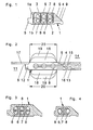
- Fig. 1 shows a cross section through a seal. It is a sealing body 1 made of a first elastomer 1a and a second elastomer 1b. Under a Elastomers are understood to be all elastic materials that come into consideration as sealing material. Count among them rubber-elastic materials, polyurethane and Polyvinyl chlorides.
- the sealing body results in cross section like a rhombus.
- a lower base side 2 and an upper one Cover page 3 run parallel to each other and serve as Sealing surfaces.
- An insertion section 4 has one Inclined surface as an assembly aid.
- a page with approach 5 serves as support after installation. Inside the Sealing body 1 are cavities 8 storey provided one above the other.
- the second elastomer 1b is stronger and harder than the first elastomer 1a and forms tension struts 6 as well as struts 7, which are quite relative to their length are fat.
- the tension and compression struts 6, 7 are arranged like a truss and separate the cavities 8.
- Die Cavities 8 are via channels 9 with the inclined surface of the Inserted portion 4 of the seal connected at compressed seal from the inclined surface as Blind holes have been drilled into the cavities 8, too continuous channels in the loaded state of the seal form.
- the channels 9 provide ventilation of the cavities 8, so that there are no air bubbles at high pressure assembled and compressed seal can form the to relax with time and thus to relaxion one would lead such a seal with compressed air bubbles.
- the seal can be made by softer coextrusion (1a) and harder (1b) elastomer material.
- the extruded strand is cut into pieces of appropriate length cut and can immediately in the appropriate environment can be used as a seal. But it is also possible the cutting ends of such strand pieces to each other vulcanize to make sealing rings.
- Such Sealing rings can be directly on the tip end of a Concrete pipe are pulled up. It is also possible to get one such a ring seal in the sleeve of a concrete pipe anchor.
- FIG. 2 The application of such a sealing ring for Sealing the gap between parts to be sealed or Buildings are shown schematically in Fig. 2.
- the main area of application is sewer construction with concrete pipes.
- On first tube has a tip end 11, which by a radial shoulder surface 12 and an axially extending Surface 13 is formed.
- the other pipe has a sleeve 14, of which the axial surface 15 is indicated.
- the Surfaces 13 and 15 are arranged parallel to one another. If the tube ends 11 and 14 are pushed into one another, there remains a sleeve gap 16 and a shoulder gap 17. Between the higher pressure side of the sleeve gap 16 and the lower pressure side with the shoulder gap 17 is the Seal 1.
- the joint 16 is thinner than the thickness of the Sealing body 1 corresponds, but has the same shape. Therefore, when assembling the pipe ends 11 and 14 comes across Pipe sleeve 14 against the inclined surface of the insertion part 4 and squeezes the seal.
- the struts come here 7 under pressure and partially giving way to the cavities 8, with part of the struts 6 coming under tension. Overall, the cavities 8 decrease, as in FIG. 2 shown.
- the struts 6, 7 develop one Restoring force, which is the contact pressure along the Contact surfaces 2, 3 of the seal 1 with those to be sealed Parts 11 and 14 noticeable, as by pressure fields 18th indicated.
- the hydrostatic pressure in the gap area 16 passes through the channels 9 into the cavities 8 and leads to a pressure increase, as by the pressure fields 19th indicated.
- the pressure fields 18, 19 act along the entire sealing portion 20 of the seal, which the Total width of the gasket in the deformed state minus the Areas 4 and 5.
- the harder elastomer 1b still has the advantage of one less relaxation compared to softer elastomer, so that through the strut structure the compressibility as in softer material can be achieved without the disadvantage of Have to put up with relaxation, which is softer Material enters after some time and then the Sealing effect reduced.
- the cavities 8 have a double function: Provision of alternative space for the struts and Attack surfaces for the print medium. Without channels 9 would Air is trapped in the cavities 8, which with the Time diffuses outwards and to relax the seal leads, whereby the restoring force and thus the effectiveness the sealing can be reduced.
- Fig. 3 shows an embodiment of the seal, at the harder elastomer 1b to a narrower one Contact area is limited, whereby the tension struts 6 only are provided in the middle between the cavities 8. So the softer material 1a takes over and below the cavities 8 next to the envelope function of Bumps and roughness such a function of Tension and compression struts.
- the struts 7 from harder Material also only extend between the Cavities 8, while the side of the cavities softer material 1a is present and in places reduced contact pressure acts as a strut.
- Fig. 4 shows a simplified embodiment of the Seal 1 for smaller cross-sections, and there is only one a series of cavities 8 instead of the two that are stacked one above the other, as in the case of the Embodiment of FIGS. 1 and 3.
- the space between the Cavities 8 is filled with harder elastomer 1b, which the Function of struts 6 and 7 takes over.
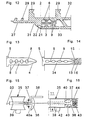
- Fig. 5 The insertion of pipes, as shown the Fig. 2 is described with considerable effort connected, and not just because of the seal must be pressed together, but also because the Relative displacement leads to large frictional forces. to Reduction of these frictional forces are common Lubricant applied, and this is the present one 5 easily possible.
- Lubricant can also be used in liquid or post-seal material
- Gel form can be used.
- swellable Polymers active in connection with moisture or water and seal creep leaks.
- Fig. 7 shows a cross section similar to that of Fig. 5, but a part 24 of the cavities 8 with Post-sealing material filled, which over perforations 25 or breakable places can emerge. You can do it all Truss gaps with lubrication and / or Fill the resealing material, the channels 9 can be omitted because the rooms 8 are not vented more is needed.
- Fig. 8 shows another simplified Embodiment compared to Fig. 7, and there is only a cavity 8 with a channel 9 and a cavity 24 for Post-sealing material with outlet perforations 25.
- Fig. 9 shows a cross section similar to that of Fig. 5, however, is on the neck or shoulder rest 5th a flap 27 connected via two joints 26 to get in to extend the shoulder gap 17 (Fig. 2).
- the Tab 27 as a load distributor and also as a shear load limiter effective.
- Fig. 10 shows an embodiment in which a Sliding jacket 28 the function of reducing friction and the Load distribution takes over.
- the sliding jacket 28 is at Putting tubes together into the shoulder gap 17 and led away from the lead-in area so that the Channel openings 9 are uncovered after assembly and not be blocked.
- Fig. 11 shows a seal for integral installation in a pipe socket in their manufacture from concrete mix.
- anchoring parts 29 are provided.
- sealing lips 30 are attached.
- a half-groove 31 for Formation of a stop for a so-called sub-sleeve the serves as a casting mold in the manufacture of the pipe sleeve, in which the seal is integrated.
- Between radial Pipe sleeve shoulder and seal is on annular maneuvering space for the tip end, that of one removable filler is ingested. The seal is shown without this packing.
- Fig. 12 shows a seal, also for integral Installation in a pipe socket, but with a flexible Filler body 32 and a load distribution element or Shear limiter 27 attached to the actual seal are connected. Access to channels 9 is via Openings 33 secured. The seal is about the Anchoring parts 29 integrated into the pipe socket.
- Figures 13 and 14 show the use of the new Seal in one embodiment as a sealing strip.
- the Cross-sectional shape 34 of this seal is similar to a nail. Alternatively, a closed frame profile is also possible. 13 shows the seal in the undeformed state.
- the internal structure corresponds to that with reference to FIGS. 1 to 4 explained principles.
- the introduction part 4 has one Wedge shape with two slopes so that the seal in one existing parallel construction joints can be driven in, as shown in Fig. 14.
- Fig. 15 shows a cross section through a Secondary seal for use in, for example underground pipe jacking combined with a Primary seal according to one of the described Embodiments works.
- the secondary seal sits there in a radial branch 40 of the socket gap.
- the seal contains a sealing body 35 and a T-shaped extension 36, 37 from web 37 and crossbar 37.
- At one end of the Cross bar 37 is a tab 38 to Mounting purposes.
- A can also be used for fastening purposes Serve extension 39.
- a filling device 50 with hose and check valve leads through the sealing body 35 into rooms 40a of the radial sleeve gap 40 to post-sealing material to insert between sealing body 35 and extension 36, 37.
- Fig. 16 shows the secondary seal of Fig. 15 in installed condition between spigot 11 and sleeve 14, and on the inside of the radial gap 40, the latter form both pipes.
- Wood is used as pipe jacking Load distribution elements 43 and the seal 35, 36, 37 in inserted this radial gap 40, the extension 39 in a groove 42 of the pipe sleeve 14 engages to close the seal hold.
- the seal can be attached using Lobe 37 on the wood 43 via nails 44.
- the secondary seal 35 is compressed, because the flanks meet when the pipes are assembled to move until the balancing and load balancing element 43 limits further compression.
- the seal consists of a Sealing body 35, the recesses or pockets 48 for Gasket material and cover flaps 45 with Perforations 47 and knotting cams 46 contains.
- the pockets 48 are by means of the cover flaps 45 and the knotting cams 46 closed, which in a groove 49 of the sealing body 35th engage. This creates a uniform sealing body, at the sealing material from the pockets 48 Compression of the seal can escape.
- the Mounting the seal for example on the already wooden ring 43 fixed to the tube, can be over nails 44 or through Gluing done (Fig. 18).
- the post-sealing material can also be installed at a later time after installation the filling device 50 are inserted.
- FIG. 19 shows a filling device 50 as Composite system between primary seal 1 and secondary seal 35, which can be activated with an injection agent, wherein via an additional generated in the filling device Contact pressure creates a better seal.
- the Primary seal 1 has one or more cavities 51, via a pressure hose 52 with the filling device 50 and the seal 35 and its cavity or cavities 53 are connected. In the or the cavities 51 and the or the cavities 53 becomes a curing agent under pressure injected and let harden.
- a test line 60 opens into both Test rooms 56 and 56a, in which shown Exemplary embodiment, the test line 60 perforations 61 having access to the test room 56a.
- the Test line 60 is through a bore 62 in the interior of the tube and from there to a test facility, not shown guided.
- the test room 56 is from when the pipe string is installed the annular surface 15 of the pipe sleeve covered. Accordingly serves the test room 56 for leak testing on the Annular surface 15, while the test room 56a for checking the Tightness on the surface 13 is used. It becomes a print medium pressed into the test spaces 56 and 56a and the pressure drop observed. If the pressure drop under one is the specified value, the seal is given as assessed and documented.
- Air or a liquid can be used as the pressure medium. for example water.
- Test room 56 should use water as the test medium be vented, for example what about a Double pipe system happen instead of a simple hose can.
- Such ventilation is also carried out if the test spaces 56 and 56a for re-sealing the Pipe socket connection should be used, what about the Test line 60 is possible.
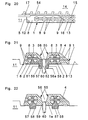
- a modified sealing arrangement 55 is shown in Fig. 22 shown.
- the connecting web 59 consists of the soft elastomer material 1a.
- Each partial seal 1 has a holding extension 57 made of the hard elastomeric material 1b and engages in a corresponding groove 58 in the annular surface 13 at the end of the spray 11.
- the sealing arrangement 55 prevented from shifting when mounting the Pipe string the sleeve is pushed over the seal.
- FIG. 23 and 24 Other ways of holding the Sealing arrangement 55 against displacement are shown in FIG. 23 and 24.
- this holding extension 57a In addition to the holding extension 57 for one
- this holding extension 57a either engages in an edge recess of the tip end (Fig. 23) or on the front radial surface of the tip end is present (Fig. 24).
- Fig. 25 shows, the position of the Sealing arrangement 55 also via oblique grooves 63 in the Annular surface 13 of the tip end.
- the twin seal assembly 55 can also be used in the Bell sleeve can be integrated, like FIGS. 26 and 27 demonstrate. For installation, refer to the description of FIGS. 11 and 12 Referenced.
- the test line 60 can radially outward (Fig. 26) or axially within the tubing to the Test device.
- test line 60 can via the Ring surface 13 of the tip end and a recess in the radial front of the tip end, and tubes 64, 65, 66 (FIG. 28) are used for this. you can also work through holes in the spigot, namely a radial bore 68 and an axially parallel bore 69 (Fig. 29).
- the two test rooms 56 and 56a are over a hole in the connecting web of the partial seal with each other connected.
- the hole can also be made through a metallic Pipe socket 67 are formed in the connecting web 59 is vulcanized.
- test line 60 can also be used for Resealing of the sealing points can be used. It is but also possible for this purpose two separate systems 60 and 70 to use, as shown in Fig. 30.
- each of the systems 60, 70 includes Check valves, so that medium in the test rooms 56th and 56a, the emergence of this medium through the other system is blocked.
- System 70 contains a connecting line 71 which runs from a central Issue, for example a test shaft in which Soil laid along the pipe string to be checked and the branch lines 72 with check valves contains that to be checked on the individual Lead seal assemblies 55. If there are leaks can be determined, can be resealed via the system 60 become.
Landscapes
- Engineering & Computer Science (AREA)
- General Engineering & Computer Science (AREA)
- Mechanical Engineering (AREA)
- Gasket Seals (AREA)
- Glass Compositions (AREA)
- Sealing Using Fluids, Sealing Without Contact, And Removal Of Oil (AREA)
- Pressure Vessels And Lids Thereof (AREA)
- Joints With Sleeves (AREA)
Claims (19)
- Etanchéité de joints entre un espace supérieur en pression et un espace inférieur en pression sur des parties et corps de construction à étancher, en particulier des canaux à base de tuyaux en béton et d'ouvrages de puits, avec les caractéristiques suivantes :caractérisé en ce que la partie subdivisée à la façon d'un treillis du corps d'étanchéité (1) occupe complètement la partie d'étanchéité (20) et constitue le joint unique, certaines zones de la partie d'étanchéité agissant dans le cas de charge comme des montants de pression (7) et d'autres zones comme des montants de traction (6) et les montants de pression (7) s'étendant généralement perpendiculairement aux surfaces d'étanchéité (2, 3) et avec une épaisseur telle qu'elles sont largement comprimées en cas de charge, mais ne se replient pas sur elles-mêmes, etun corps d'étanchéité (1) dans le joint (16) à étancher présente une partie d'introduction (4) et une partie d'étanchéité (20) avec des cavités (8 ; 24 ; 51), qui subdivisent une partie du corps d'étanchéité à la façon d'un treillis, la partie d'étanchéité (20) présentant des surfaces d'étanchéité (2, 3) à peu près selon la forme de la partie du joint à étancher (16),
en ce que le corps d'étanchéité (1) présente une zone périphérique avec un élastomère (la) plus souple et une zone centrale avec un élastomère (1b) plus dur, zone centrale dans laquelle s'étendent au moins les montants de pression (7). - Etanchéité selon la revendication 1, caractérisée en ce qu'au moins une partie des cavités (8) est reliée au moyen d'un ou de plusieurs canaux d'arrivée de pression (9) au joint (16) à étancher, afin d'utiliser la pression dans l'espace supérieur en pression pour augmenter la pression d'appui.
- Etanchéité selon l'une quelconque des revendications 1 à 2,
caractérisée en ce que les surfaces d'étanchéité (2, 3) de la partie d'étanchéité (20) sont parallèles entre elles et en ce que les montants de pression (7), les montants de traction (6) et les cavités (8, 24, 51) sont disposés entre les surfaces d'étanchéité (2, 3). - Etanchéité selon la revendication 3,
caractérisée en ce que la largeur de la partie d'étanchéité (20) est supérieure à la largeur du joint (16) à étancher et a été choisie pour s'adapter aux aspérités de surface des parties (11, 14) à étancher et en fonction de la pression à étancher. - Etanchéité selon l'une quelconque des revendications 1 à 4,
caractérisée en ce que la partie d'introduction (4) présente des cavités (21) remplies de matériau fluide, qui se vident au moins partiellement lors de l'effet de la pression, afin de rendre le matériau fluide efficace comme agent lubrifiant et/ou agent d'étanchéité complémentaire. - Etanchéité selon l'une quelconque des revendications 1 à 5,
caractérisée en ce que, dans la partie d'étanchéité (20), il est prévu une ou plusieurs cavités (24) remplies avec du matériau d'étanchéité complémentaire, qui se vident au moins partiellement lors de l'effet de la pression. - Etanchéité selon l'une quelconque des revendications 1 à 6,
caractérisée par une enveloppe de glissement (28) efficace comme aide au montage, qui est disposée et conçue de façon qu'elle ne bloque pas les canaux (9) allant aux cavités (8) après le montage du joint (1). - Etanchéité selon l'une quelconque des revendications 1 à 7, caractérisée en ce qu'une patte de support (27), qui s'étend dans un joint (17) en direction de l'espace à pression faible, est formée sur le corps d'étanchéité (1).
- Etanchéité selon l'une quelconque des revendications 1 à 8, caractérisée en ce que le corps d'étanchéité (1) est conçu pour l'intégration dans un manchon de tube (14) et présente à cet effet des prolongements d'ancrage (29) et en ce que le corps d'étanchéité (1) est réalisé pour l'appui (31) sur un moule de coulée et un joint (30) d'une surface d'étanchéité (3) par rapport à la pénétration de ciment-eau.
- Etanchéité selon la revendication 2,
caractérisée en ce que le corps d'étanchéité présente une partie de manoeuvre (32) souple, qui est reliée à l'espace supérieur en pression et présente des orifices de passage (33) afin d'amener la pression éventuellement supérieure aux canaux d'arrivée de pression (9). - Dispositif contenant une étanchéité (1) selon l'une quelconque des revendications 1 à 10 comme étanchéité primaire et étanchéité secondaire (35), qui est disposé dans une fente radiale (40) et présente des espaces (40a, 48) pour le logement de matériau d'étanchéité.
- Dispositif selon la revendication 11,
caractérisé par un dispositif d'amenée (50) pour du matériau d'étanchéité, qui permet d'amener du matériau d'étanchéité sous pression aux espaces de remplissage (40a, 48) de l'étanchéité secondaire. - Dispositif selon la revendication 11 ou 12,
caractérisé en ce que le corps d'étanchéité (1) formant l'étanchéité primaire, et l'étanchéité secondaire (35), sont reliés entre eux par un flexible de pression (52) pour l'arrivée de matériau de soutien, lequel peut être amené aux cavités (51, 53) fermées à l'intérieur de l'étanchéité (1, 35) concernée. - Dispositif ou étanchéité selon l'une quelconque des revendications 1 à 13,
caractérisé en ce que l'une des parties (14) à étancher présente une couche (54) à base d'un tel matériau, qui a tendance à se souder avec le matériau du corps d'étanchéité (1). - Dispositif ou étanchéité selon l'une quelconque des revendications 1 à 14,
caractérisé par un dispositif de joint jumelé (55) avec deux corps d'étanchéité (1), entre lesquels est formé au moins un espace d'essai (56), qui est accessible par l'extérieur par une conduite d'essai (60) à des fins d'essai et/ou une étanchéité complémentaire. - Etanchéité ou dispositif selon la revendication 15,
caractérisé en ce qu'un espace d'essai (56, 56a) est prévu sur chaque côté de joint (2, 3) du dispositif jumelé (55), espaces qui sont raccordés à la même conduite (60). - Etanchéité ou dispositif selon la revendication 15 ou 16,
caractérisé par des moyens d'engagement (57, 58, 57a, 63) sur le corps de joint (1) et l'une des parties (11) à étancher. - Etanchéité ou dispositif selon l'une quelconque des revendications 15 à 17,
caractérisé en ce que la conduite d'essai et/ou la conduite d'étanchéité complémentaire (60) est (sont) guidée(s) dans la zone d'une fente (40) radiale entre les parties (11, 14) à étancher, afin de donner accès à partir de là à l'espace d'essai (56, 56a). - Etanchéité ou dispositif selon l'une quelconque des revendications 15 à 18,
caractérisé par un système de conduite (70), qui permet d'accéder à plusieurs espaces d'essai et/ou d'étanchéité (56, 56a).
Applications Claiming Priority (2)
| Application Number | Priority Date | Filing Date | Title |
|---|---|---|---|
| DE29712235U | 1997-07-11 | ||
| DE29712235U DE29712235U1 (de) | 1997-07-11 | 1997-07-11 | Dichtung mit Hohlräumen |
Publications (3)
| Publication Number | Publication Date |
|---|---|
| EP0890772A2 EP0890772A2 (fr) | 1999-01-13 |
| EP0890772A3 EP0890772A3 (fr) | 2001-01-10 |
| EP0890772B1 true EP0890772B1 (fr) | 2003-09-17 |
Family
ID=8042967
Family Applications (1)
| Application Number | Title | Priority Date | Filing Date |
|---|---|---|---|
| EP98112552A Expired - Lifetime EP0890772B1 (fr) | 1997-07-11 | 1998-07-07 | Joint d'étancheité avec de cavités |
Country Status (4)
| Country | Link |
|---|---|
| US (1) | US6264207B1 (fr) |
| EP (1) | EP0890772B1 (fr) |
| AT (1) | ATE250195T1 (fr) |
| DE (2) | DE29712235U1 (fr) |
Cited By (2)
| Publication number | Priority date | Publication date | Assignee | Title |
|---|---|---|---|---|
| DE202015101734U1 (de) | 2015-04-09 | 2015-05-13 | Theodor Cordes Gmbh & Co. Kg | Integrierte Dichtung mit Scherkraft-Stützschulter |
| DE102021204982A1 (de) | 2021-05-18 | 2022-11-24 | Robert Bosch Gesellschaft mit beschränkter Haftung | Vorrichtung zur Herstellung einer fluidischen Verbindung und deren Abdichtung |
Families Citing this family (6)
| Publication number | Priority date | Publication date | Assignee | Title |
|---|---|---|---|---|
| GB2340111B (en) * | 1998-08-04 | 2002-09-11 | United Kingdom Nirex Ltd | Unitary double ring seal |
| JP4408389B2 (ja) * | 2004-05-10 | 2010-02-03 | サンデン株式会社 | 斜板式圧縮機 |
| JP4953841B2 (ja) * | 2006-03-31 | 2012-06-13 | 京セラ株式会社 | 熱電モジュール |
| CN104455420B (zh) * | 2014-11-19 | 2016-10-05 | 张家港市三利密封合金材料有限公司 | 一种复合结构的密封条 |
| DE102018101178A1 (de) * | 2018-01-19 | 2019-07-25 | J.H. & Wilhelm Finger Gmbh & Co Kg | Betonrohr mit einem einer Innenauskleidung bildenden Kunststoffrohr |
| CN114623298B (zh) * | 2022-02-09 | 2024-01-26 | 华能济宁运河发电有限公司 | 一种用于输灰系统的管道之间防渗漏设备 |
Family Cites Families (25)
| Publication number | Priority date | Publication date | Assignee | Title |
|---|---|---|---|---|
| DE551816C (de) | 1928-05-26 | 1932-06-06 | Donald Hugh Baillie Reynolds | Stossfugendichtung fuer Rohre |
| US2615741A (en) * | 1949-07-11 | 1952-10-28 | Hamilton Kent Mfg Company | Sealing ring |
| GB759387A (en) * | 1953-12-04 | 1956-10-17 | Horace Denton Morgan | Improvements in and relating to pipe joints |
| US3058752A (en) * | 1959-06-30 | 1962-10-16 | Nat Coupling Co Inc | Gasket |
| US3173699A (en) * | 1962-08-24 | 1965-03-16 | Hamilton Kent Mfg Co | Annular gasket |
| GB1273136A (en) * | 1968-08-02 | 1972-05-03 | Corrugated Packing Sheet Metal | Improvements in or relating to sealing means |
| US3762826A (en) * | 1970-08-20 | 1973-10-02 | Watson Bowman Associates | Sealing strip |
| FR2148365B1 (fr) * | 1971-08-11 | 1973-08-10 | Hutchinson Cie Ets | |
| IT965354B (it) * | 1972-09-14 | 1974-01-31 | Vianini Spa | Dispositivo per il collaudo dall interno su giunti di tuba zioni e simili e per prove di impermeabilita o di assorbimento su pareti di tubazioni condotte o recipienti in genere |
| JPS60184794A (ja) * | 1984-03-02 | 1985-09-20 | 動力炉・核燃料開発事業団 | 遠隔着脱用継手 |
| US4522413A (en) * | 1984-06-29 | 1985-06-11 | Elastomer Seals, Inc. | Pavement joint seal with chevron-shaped walls |
| DE3442653C1 (de) * | 1984-11-22 | 1986-06-19 | Daimler-Benz Ag, 7000 Stuttgart | Abdichtung fuer den Spalt zwischen einem starren Schiebedeckel und einem diesen umgebenden festen Dachbereich eines Kraftwagens |
| DE3601757A1 (de) * | 1986-01-22 | 1987-07-23 | Muecher Hermann Gmbh | Elastische gleitdichtung |
| US4743036A (en) * | 1986-04-16 | 1988-05-10 | Mm Systems Corporation | Compression seal |
| DE3815142A1 (de) * | 1988-05-04 | 1989-11-16 | Phoenix Ag | Akitiverbare dichtung, insbesondere tuebbing-dichtung |
| DE4108851A1 (de) * | 1990-03-24 | 1991-09-26 | Phoenix Ag | Steckmuffenverbindung |
| DE9017653U1 (de) * | 1990-11-02 | 1991-05-29 | Baustoffwerk Sehn GmbH & Co., 6670 St Ingbert | Dichtung zwischen aneinanderschließenden Betonrohren |
| DE4107994A1 (de) * | 1991-03-13 | 1992-09-17 | Cordes Theodor Gmbh & Co Kg | Dichtungsring zur abdichtung der fuge zwischen dem spitzende und der glockenmuffe einer verbindung rohrfoermiger bauteile |
| US5143381A (en) * | 1991-05-01 | 1992-09-01 | Pipe Gasket & Supply Co., Inc. | Pipe joint seal |
| AU645148B2 (en) * | 1991-11-21 | 1994-01-06 | Forsheda Ab | A sealing device |
| DE4236368C2 (de) * | 1992-10-28 | 1997-07-17 | Thomas Dipl Ing Lammering | Gleitringdichtung mit integrierter Verpreßeinrichtung |
| EP0686245B1 (fr) * | 1993-12-15 | 2000-06-14 | Forsheda AB | Dispositif d'etancheite, element de moulage et conduit |
| SE515033C2 (sv) * | 1995-12-27 | 2001-06-05 | Forsheda Ab | Tätningsanordning |
| DE19601652A1 (de) * | 1996-01-18 | 1997-07-24 | Sander Karl Heinz Gmbh & Co Kg | Beton-, Steinzeug- oder Gußrohr |
| NO305095B1 (no) * | 1997-06-06 | 1999-03-29 | Alsthom Cge Alcatel | FremgangsmÕte og anordning for forsegling |
-
1997
- 1997-07-11 DE DE29712235U patent/DE29712235U1/de not_active Expired - Lifetime
-
1998
- 1998-07-07 AT AT98112552T patent/ATE250195T1/de not_active IP Right Cessation
- 1998-07-07 EP EP98112552A patent/EP0890772B1/fr not_active Expired - Lifetime
- 1998-07-07 DE DE59809618T patent/DE59809618D1/de not_active Expired - Lifetime
- 1998-07-09 US US09/112,599 patent/US6264207B1/en not_active Expired - Fee Related
Cited By (3)
| Publication number | Priority date | Publication date | Assignee | Title |
|---|---|---|---|---|
| DE202015101734U1 (de) | 2015-04-09 | 2015-05-13 | Theodor Cordes Gmbh & Co. Kg | Integrierte Dichtung mit Scherkraft-Stützschulter |
| EP3078884A1 (fr) | 2015-04-09 | 2016-10-12 | Theodor Cordes GmbH & Co. KG | Joint integre comprenant un epaulement de force de cisaillement |
| DE102021204982A1 (de) | 2021-05-18 | 2022-11-24 | Robert Bosch Gesellschaft mit beschränkter Haftung | Vorrichtung zur Herstellung einer fluidischen Verbindung und deren Abdichtung |
Also Published As
| Publication number | Publication date |
|---|---|
| DE29712235U1 (de) | 1998-11-12 |
| EP0890772A2 (fr) | 1999-01-13 |
| ATE250195T1 (de) | 2003-10-15 |
| DE59809618D1 (de) | 2003-10-23 |
| US6264207B1 (en) | 2001-07-24 |
| EP0890772A3 (fr) | 2001-01-10 |
Similar Documents
| Publication | Publication Date | Title |
|---|---|---|
| DE60034393T2 (de) | Rohrverbindung | |
| DE69219562T2 (de) | Dichtungsvorrichtung | |
| DE69600492T2 (de) | Dichtung und ihr herstellungsverfahren | |
| DE4229609C2 (de) | Abdichtung zwischen zwei ineinandersteckbaren Teilen | |
| DE2658428A1 (de) | Dichtung zum abdichten zweier maschinenelemente und verwendung der dichtung | |
| WO1996023958A1 (fr) | Garniture d'etancheite pour segments de galeries de tunnel | |
| DE3414180A1 (de) | Dichtungseinrichtung fuer aneinanderstossende, zumindest etwa rohrfoermige bauteile, insbesondere fuer betonformteile | |
| CH663262A5 (de) | Durchfuehrung fuer leitungen, wie kabel oder rohre durch eine wandoeffnung und vorrichtung zur herstellung einer laibung fuer eine solche durchfuehrung in einer betonwand. | |
| EP2147191A2 (fr) | Vérin hydraulique présentant des tubes extérieurs et intérieurs à parois minces | |
| EP0340659B1 (fr) | Joint pouvant être activé, en particulier pour anneaux de cuvelage | |
| EP2414633B1 (fr) | Système d'étanchéité pour la construction de puits et de tunnels | |
| EP0890772A2 (fr) | Joint d'étancheité avec de cavités | |
| EP0218987A2 (fr) | Méthode pour la mise en place d'un élément de construction au travers d'un rideau de palplanches dans une formation du sol comportant de l'eau sous pression ainsi qu'un dispositif pour la mise en oeuvre de la méthode | |
| EP1165937A2 (fr) | Ensemble etanche | |
| DE69529964T2 (de) | Biegsame Röhrenfuge | |
| EP2674569A1 (fr) | Garniture de joint pour avancées tubulaires | |
| DE3543808A1 (de) | Verfahren zur abdichtung von tuebbingen und dichtungsrahmen zur durchfuehrung des verfahrens | |
| DE2948543A1 (de) | Fugenausbildung in betonschichten, insbesondere in betonauskleidungen von wasserkanaelen | |
| EP0574559B1 (fr) | Procede de prevention du deplacement d'une moulure profilee d'etancheite par rapport a un element de tunnel et moulure profilee d'etancheite produite selon ce procede | |
| DE2542004A1 (de) | Fugenabdichtung zwischen aneinanderstossenden bauteilen aus mineralischen stoffen mittels eines fugenbandes aus thermoplastischem kunststoff | |
| EP0758703A1 (fr) | Joint de bétonnage | |
| EP0859183B1 (fr) | Anneau d'étanchéité pour anneaux de puits d'accès | |
| DE69905819T2 (de) | Dichtanordnung für Tunnel-Segmente | |
| DE19911341A1 (de) | Abdichtende Kupplung zur Verbindung zweier Rohrenden | |
| DE3404074A1 (de) | Verfahren zum herstellen einer schlitzwand aus beton |
Legal Events
| Date | Code | Title | Description |
|---|---|---|---|
| PUAI | Public reference made under article 153(3) epc to a published international application that has entered the european phase |
Free format text: ORIGINAL CODE: 0009012 |
|
| AK | Designated contracting states |
Kind code of ref document: A2 Designated state(s): AT BE CH DE DK ES FR GB IT LI LU NL PT SE |
|
| AX | Request for extension of the european patent |
Free format text: AL;LT;LV;MK;RO;SI |
|
| RIC1 | Information provided on ipc code assigned before grant |
Free format text: 7F 16L 17/06 A, 7F 16L 21/035 B, 7E 04B 1/68 B, 7F 16J 15/02 B, 7F 16L 21/03 B, 7F 16L 17/10 B, 7E 03F 3/04 B |
|
| PUAL | Search report despatched |
Free format text: ORIGINAL CODE: 0009013 |
|
| AK | Designated contracting states |
Kind code of ref document: A3 Designated state(s): AT BE CH CY DE DK ES FI FR GB GR IE IT LI LU MC NL PT SE |
|
| AX | Request for extension of the european patent |
Free format text: AL;LT;LV;MK;RO;SI |
|
| RIC1 | Information provided on ipc code assigned before grant |
Free format text: 7F 16L 17/06 A, 7F 16L 21/035 B, 7E 04B 1/68 B, 7F 16J 15/02 B, 7F 16L 21/03 B, 7F 16L 17/10 B, 7E 03F 3/04 B, 7G 01M 3/28 B |
|
| 17P | Request for examination filed |
Effective date: 20010705 |
|
| AKX | Designation fees paid |
Free format text: AT BE CH DE DK ES FR GB IT LI LU NL PT SE |
|
| 17Q | First examination report despatched |
Effective date: 20011108 |
|
| GRAH | Despatch of communication of intention to grant a patent |
Free format text: ORIGINAL CODE: EPIDOS IGRA |
|
| GRAH | Despatch of communication of intention to grant a patent |
Free format text: ORIGINAL CODE: EPIDOS IGRA |
|
| GRAA | (expected) grant |
Free format text: ORIGINAL CODE: 0009210 |
|
| AK | Designated contracting states |
Kind code of ref document: B1 Designated state(s): AT BE CH DE DK ES FR GB IT LI LU NL PT SE |
|
| PG25 | Lapsed in a contracting state [announced via postgrant information from national office to epo] |
Ref country code: IT Free format text: LAPSE BECAUSE OF FAILURE TO SUBMIT A TRANSLATION OF THE DESCRIPTION OR TO PAY THE FEE WITHIN THE PRESCRIBED TIME-LIMIT;WARNING: LAPSES OF ITALIAN PATENTS WITH EFFECTIVE DATE BEFORE 2007 MAY HAVE OCCURRED AT ANY TIME BEFORE 2007. THE CORRECT EFFECTIVE DATE MAY BE DIFFERENT FROM THE ONE RECORDED. Effective date: 20030917 Ref country code: GB Free format text: LAPSE BECAUSE OF FAILURE TO SUBMIT A TRANSLATION OF THE DESCRIPTION OR TO PAY THE FEE WITHIN THE PRESCRIBED TIME-LIMIT Effective date: 20030917 |
|
| REG | Reference to a national code |
Ref country code: GB Ref legal event code: FG4D Free format text: NOT ENGLISH |
|
| REG | Reference to a national code |
Ref country code: SE Ref legal event code: TRGR |
|
| REG | Reference to a national code |
Ref country code: CH Ref legal event code: EP |
|
| REF | Corresponds to: |
Ref document number: 59809618 Country of ref document: DE Date of ref document: 20031023 Kind code of ref document: P |
|
| PG25 | Lapsed in a contracting state [announced via postgrant information from national office to epo] |
Ref country code: DK Free format text: LAPSE BECAUSE OF FAILURE TO SUBMIT A TRANSLATION OF THE DESCRIPTION OR TO PAY THE FEE WITHIN THE PRESCRIBED TIME-LIMIT Effective date: 20031217 |
|
| PG25 | Lapsed in a contracting state [announced via postgrant information from national office to epo] |
Ref country code: PT Free format text: LAPSE BECAUSE OF FAILURE TO SUBMIT A TRANSLATION OF THE DESCRIPTION OR TO PAY THE FEE WITHIN THE PRESCRIBED TIME-LIMIT Effective date: 20031226 |
|
| PG25 | Lapsed in a contracting state [announced via postgrant information from national office to epo] |
Ref country code: ES Free format text: LAPSE BECAUSE OF FAILURE TO SUBMIT A TRANSLATION OF THE DESCRIPTION OR TO PAY THE FEE WITHIN THE PRESCRIBED TIME-LIMIT Effective date: 20031228 |
|
| GBV | Gb: ep patent (uk) treated as always having been void in accordance with gb section 77(7)/1977 [no translation filed] |
Effective date: 20030917 |
|
| ET | Fr: translation filed | ||
| PG25 | Lapsed in a contracting state [announced via postgrant information from national office to epo] |
Ref country code: LU Free format text: LAPSE BECAUSE OF NON-PAYMENT OF DUE FEES Effective date: 20040707 Ref country code: AT Free format text: LAPSE BECAUSE OF NON-PAYMENT OF DUE FEES Effective date: 20040707 |
|
| PLBE | No opposition filed within time limit |
Free format text: ORIGINAL CODE: 0009261 |
|
| STAA | Information on the status of an ep patent application or granted ep patent |
Free format text: STATUS: NO OPPOSITION FILED WITHIN TIME LIMIT |
|
| PG25 | Lapsed in a contracting state [announced via postgrant information from national office to epo] |
Ref country code: LI Free format text: LAPSE BECAUSE OF NON-PAYMENT OF DUE FEES Effective date: 20040731 Ref country code: CH Free format text: LAPSE BECAUSE OF NON-PAYMENT OF DUE FEES Effective date: 20040731 |
|
| 26N | No opposition filed |
Effective date: 20040618 |
|
| REG | Reference to a national code |
Ref country code: CH Ref legal event code: PL |
|
| REG | Reference to a national code |
Ref country code: FR Ref legal event code: PLFP Year of fee payment: 19 |
|
| REG | Reference to a national code |
Ref country code: FR Ref legal event code: PLFP Year of fee payment: 20 |
|
| PGFP | Annual fee paid to national office [announced via postgrant information from national office to epo] |
Ref country code: NL Payment date: 20170720 Year of fee payment: 20 |
|
| PGFP | Annual fee paid to national office [announced via postgrant information from national office to epo] |
Ref country code: FR Payment date: 20170720 Year of fee payment: 20 Ref country code: DE Payment date: 20170731 Year of fee payment: 20 |
|
| PGFP | Annual fee paid to national office [announced via postgrant information from national office to epo] |
Ref country code: SE Payment date: 20170724 Year of fee payment: 20 Ref country code: BE Payment date: 20170720 Year of fee payment: 20 |
|
| REG | Reference to a national code |
Ref country code: DE Ref legal event code: R071 Ref document number: 59809618 Country of ref document: DE |
|
| REG | Reference to a national code |
Ref country code: NL Ref legal event code: MK Effective date: 20180706 |
|
| REG | Reference to a national code |
Ref country code: SE Ref legal event code: EUG |
|
| REG | Reference to a national code |
Ref country code: BE Ref legal event code: MK Effective date: 20180707 |