EP0891005A1 - Gruppenantenne mit Störungschutz - Google Patents
Gruppenantenne mit Störungschutz Download PDFInfo
- Publication number
- EP0891005A1 EP0891005A1 EP98401718A EP98401718A EP0891005A1 EP 0891005 A1 EP0891005 A1 EP 0891005A1 EP 98401718 A EP98401718 A EP 98401718A EP 98401718 A EP98401718 A EP 98401718A EP 0891005 A1 EP0891005 A1 EP 0891005A1
- Authority
- EP
- European Patent Office
- Prior art keywords
- reception
- antenna
- adaptive
- radiating elements
- reduced
- Prior art date
- Legal status (The legal status is an assumption and is not a legal conclusion. Google has not performed a legal analysis and makes no representation as to the accuracy of the status listed.)
- Granted
Links
- 230000003044 adaptive effect Effects 0.000 claims abstract description 61
- 230000015572 biosynthetic process Effects 0.000 claims abstract description 61
- 230000005540 biological transmission Effects 0.000 claims abstract description 6
- 238000012937 correction Methods 0.000 claims description 21
- 238000003491 array Methods 0.000 claims description 2
- 238000005755 formation reaction Methods 0.000 abstract description 56
- 230000005855 radiation Effects 0.000 description 15
- 238000010586 diagram Methods 0.000 description 12
- 230000008901 benefit Effects 0.000 description 4
- 238000011282 treatment Methods 0.000 description 4
- 230000000737 periodic effect Effects 0.000 description 3
- 239000007787 solid Substances 0.000 description 3
- 238000011144 upstream manufacturing Methods 0.000 description 3
- 241000861223 Issus Species 0.000 description 2
- 230000009471 action Effects 0.000 description 2
- 230000000694 effects Effects 0.000 description 2
- 238000001914 filtration Methods 0.000 description 2
- 238000006386 neutralization reaction Methods 0.000 description 2
- 230000010363 phase shift Effects 0.000 description 2
- 230000009467 reduction Effects 0.000 description 2
- 238000004458 analytical method Methods 0.000 description 1
- 230000008859 change Effects 0.000 description 1
- 230000001427 coherent effect Effects 0.000 description 1
- 230000002301 combined effect Effects 0.000 description 1
- 230000003247 decreasing effect Effects 0.000 description 1
- 230000008030 elimination Effects 0.000 description 1
- 238000003379 elimination reaction Methods 0.000 description 1
- 238000005286 illumination Methods 0.000 description 1
- 238000000034 method Methods 0.000 description 1
- 238000004377 microelectronic Methods 0.000 description 1
- 230000008520 organization Effects 0.000 description 1
- 238000005070 sampling Methods 0.000 description 1
- 230000009897 systematic effect Effects 0.000 description 1
Images

Classifications
-
- H—ELECTRICITY
- H04—ELECTRIC COMMUNICATION TECHNIQUE
- H04K—SECRET COMMUNICATION; JAMMING OF COMMUNICATION
- H04K3/00—Jamming of communication; Counter-measures
- H04K3/20—Countermeasures against jamming
- H04K3/22—Countermeasures against jamming including jamming detection and monitoring
- H04K3/224—Countermeasures against jamming including jamming detection and monitoring with countermeasures at transmission and/or reception of the jammed signal, e.g. stopping operation of transmitter or receiver, nulling or enhancing transmitted power in direction of or at frequency of jammer
- H04K3/228—Elimination in the received signal of jamming or of data corrupted by jamming
-
- G—PHYSICS
- G01—MEASURING; TESTING
- G01S—RADIO DIRECTION-FINDING; RADIO NAVIGATION; DETERMINING DISTANCE OR VELOCITY BY USE OF RADIO WAVES; LOCATING OR PRESENCE-DETECTING BY USE OF THE REFLECTION OR RERADIATION OF RADIO WAVES; ANALOGOUS ARRANGEMENTS USING OTHER WAVES
- G01S7/00—Details of systems according to groups G01S13/00, G01S15/00, G01S17/00
- G01S7/02—Details of systems according to groups G01S13/00, G01S15/00, G01S17/00 of systems according to group G01S13/00
- G01S7/36—Means for anti-jamming, e.g. ECCM, i.e. electronic counter-counter measures
-
- H—ELECTRICITY
- H01—ELECTRIC ELEMENTS
- H01Q—ANTENNAS, i.e. RADIO AERIALS
- H01Q21/00—Antenna arrays or systems
- H01Q21/06—Arrays of individually energised antenna units similarly polarised and spaced apart
- H01Q21/22—Antenna units of the array energised non-uniformly in amplitude or phase, e.g. tapered array or binomial array
-
- H—ELECTRICITY
- H01—ELECTRIC ELEMENTS
- H01Q—ANTENNAS, i.e. RADIO AERIALS
- H01Q3/00—Arrangements for changing or varying the orientation or the shape of the directional pattern of the waves radiated from an antenna or antenna system
- H01Q3/26—Arrangements for changing or varying the orientation or the shape of the directional pattern of the waves radiated from an antenna or antenna system varying the relative phase or relative amplitude of energisation between two or more active radiating elements; varying the distribution of energy across a radiating aperture
- H01Q3/2605—Array of radiating elements provided with a feedback control over the element weights, e.g. adaptive arrays
- H01Q3/2611—Means for null steering; Adaptive interference nulling
- H01Q3/2617—Array of identical elements
-
- G—PHYSICS
- G01—MEASURING; TESTING
- G01S—RADIO DIRECTION-FINDING; RADIO NAVIGATION; DETERMINING DISTANCE OR VELOCITY BY USE OF RADIO WAVES; LOCATING OR PRESENCE-DETECTING BY USE OF THE REFLECTION OR RERADIATION OF RADIO WAVES; ANALOGOUS ARRANGEMENTS USING OTHER WAVES
- G01S7/00—Details of systems according to groups G01S13/00, G01S15/00, G01S17/00
- G01S7/02—Details of systems according to groups G01S13/00, G01S15/00, G01S17/00 of systems according to group G01S13/00
- G01S7/28—Details of pulse systems
- G01S7/2813—Means providing a modification of the radiation pattern for cancelling noise, clutter or interfering signals, e.g. side lobe suppression, side lobe blanking, null-steering arrays
-
- H—ELECTRICITY
- H04—ELECTRIC COMMUNICATION TECHNIQUE
- H04K—SECRET COMMUNICATION; JAMMING OF COMMUNICATION
- H04K2203/00—Jamming of communication; Countermeasures
- H04K2203/30—Jamming or countermeasure characterized by the infrastructure components
- H04K2203/32—Jamming or countermeasure characterized by the infrastructure components including a particular configuration of antennas
Definitions
- the present invention relates to a wave antenna radio or ultrasonic, network type, anti-jamming in reception, with radiant elements or groups of elements radiators individually equipped with active or passive modules amplitude and phase controlled allowing pointing, at emission as at reception, by analog beam formation and with means of adaptive beam formation by calculation performing reception jamming.
- the active or passive modules ordered in amplitude and in phase will be simply called ordered modules for the sole purpose of simplification.
- a network antenna consists of an assembly of elements radiant distributed in a network, mostly surface, according to a mesh of about half ⁇ / 2 of the wavelength of the radiation emitted or received to avoid the appearance of network lobes disrupting the directivity of the antenna.
- the dimensioning of an antenna depends on the amplitude of the signal to be received, i.e. the desired signal-to-noise ratio in reception and the desired angular resolution.
- the signals to be received are characterized by a uniform power surface density instead of reception so that the strength of the received useful signal increases as the useful surface of the antenna.
- the angular resolution is, for its part, defined in each direction by the linear dimension L of the antenna in the direction considered relative to the wavelength ⁇ in the relation ⁇ / L, the solid angular resolution being defined in the ratio ⁇ 2 / S or S is the surface of the antenna.
- the absence of certain radiating elements means that the mesh at approximately ⁇ / 2 is no longer respected which leads to the appearance of network lobes if the disposition missing radiating elements is periodic or diffuse lobes if this arrangement is random. It is important to minimize these network and diffuse lobes.
- a network antenna can be mechanically pointing or electronic.
- the score is electronic, it is done at the show by an analog beam formation while at the reception, it can be done either by an analog beam formation, or by a beamforming by calculation.
- Analog beam formation requires equipping individually the radiating elements of the antenna or groups radiant elements with active or passive modules controlled by amplitude and phase making it possible to orient the plane of the waves emitted or received in the desired direction. It has the advantage of also working both at transmission and at reception.
- an order amplitude or a distribution network allow weighting in amplitude.
- Beam formation by calculation consists in digitizing the signals received by each of the radiating elements after they have been demodulated in a coherent way and then to phase them individually and to make it a weighted sum by calculator to orient the plane of waves received in the desired direction. It has the advantage of giving a great flexibility in beam formation since it is possible to simultaneously form by calculation several beams pointing in different directions. It also allows, when it is adaptive, to anti-jamming by adjusting the position of the zeros in the radiation diagram. However, it has the disadvantage of not being usable at transmission, to require expensive equipment for the scanning the signals from the radiant elements and claiming a very large amount of calculations.
- an antenna network is often used for both transmitting and receiving it is usual to equip the radiating elements with a network antenna individually or in groups, of modules ordered allowing a pointing by analog beam formation and regrouping in reception of the radiating elements of the antenna in sub-networks for perform anti-jamming by a reduced adaptive formation of beam by calculation, grouping in reception of the elements radiant in surface arrays and training adaptive reduced beam by the calculation being carried out in the two pointing directions, deposit and site.
- Reduced adaptive beamforming by calculation generates a radiation diagram of which the main lobe retains the pointing direction produced by the modules ordered but whose the zeros are moved towards the jammers, this by playing mainly on the relative amplitudes and possibly on the second order, on the relative phase shifts imposed on the reception signals of the subnets.
- this diagram of radiation keeps the disadvantage of presenting network lobes to discrete angular positions or diffuse lobes depending on whether the organization surface sub-networks in the antenna is periodic or random because subnets necessarily have spaced phase centers a distance greater than or equal to ⁇ reflecting a subsampling of the antenna surface.
- the non-linear processing of grouping of reception signals resulting from the two reduced beam formations by calculation can generate intermodulation products if several signals are present in the same distance cell of the same cell angular: a target and a clutter for example.
- This drawback can be bypassed by Doppler filtering upstream of the grouping of the two reception signals resulting from reduced beam formations by the calculation but this means that the filtering equipment must be doubled Doppler.
- the object of the present invention is a pointing network antenna by analog beam formation and anti-jamming in reception at means of adaptive reduced beam formations by calculation resulting in a low level of side lobes or diffuse lobes, that this network antenna is full, incomplete or rarefied.
- Anti-jamming is thus carried out upon reception of an antenna electronically-pointing network by analog beam formation at by means of two adaptive beam formations reduced by calculation successive resulting in a reduced processing load for the antenna compared to that of a full adaptive beam formation by the calculation based on the reception signals delivered individually by the controlled modules connected to the radiating elements of the antenna while providing a comparable reduction in disturbance from the side lobes and network lobes.
- the directions of the two sets of subnets linear are orthogonal and oriented one according to the site plan and the other according to the network antenna field plan.
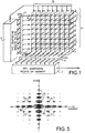
- Figure 1 shows a planar array antenna gathering a set of radiating elements 1 uniformly distributed over m columns and n lines according to a mesh of approximately ⁇ / 2 ( ⁇ being the wavelength antenna usage) to meet the sampling criteria of surface ensuring the absence of network lobes in the case of a wide angle electronic scan.
- Each radiating element 1 is individually equipped with a phase shift module controlled 2 supplemented by a controlled attenuator module 3.
- the ordered modules 2, 3 are ordered, on the first order, by an antenna pointing circuit (not shown) which directs, both on transmission and on reception, the antenna wave plane in the desired direction in deposit and site, playing mainly on the phases and incidentally on the signal levels of the different radiating elements to shape the shape of the lobe (s).
- the outputs of the ordered modules 2, 3 are subject to two groupings: a first grouping in n horizontal alignments of m elements parallel to the bearing axis and a second grouping in m vertical alignments of n elements parallel to the site axis. These two groupings are obtained by means of two crossed and superimposed sets of distributors.
- the latter share the reception signal available at the output of a controlled module 2, 3 into a first and a second component available in parallel and combine on the one hand, the first component with the first components from the other controlled modules 2, 3 belonging to the same horizontal alignment to form a reception signal ⁇ gi, and on the other hand, the second component with the second components from the other controlled modules belonging to the same vertical alignment to form a reception signal ⁇ si .
- reception signals ⁇ gi of all the horizontal alignments of radiating elements 1 are applied by means of a bank 4 of analog-digital converters to a first circuit 5 of adaptive reduced beam formation by the calculation elaborating correction commands to the ordered modules 2, 3 being added, in the second order, to the commands developed by the pointing circuit.
- the reception signals ⁇ if from all the vertical alignments of radiating elements 1 are applied by means of another bank 6 of analog-digital converters to a second circuit 7 of adaptive formation reduced in beam by the calculation forming a reception channel of the global antenna.
- the first circuit 5 of reduced adaptive beam formation by calculation analyzes the disturbances in elevation of the wave plane received by the network antenna and deduces the corrections to be made to the commands designed by the pointing circuit for the various modules controlled 2, 3 to attenuate the disturbances detected. It allows to create, in the radiation pattern on reception of the antenna network, crevices in site in the form of horizontal valleys for eliminate disturbing signals shifted in elevation relative to the axis of pointing the antenna.
- the second circuit 7 of adaptive training reduced by beam by calculation analyzes the disturbances in plane bearing wave received by the network antenna and deduces the amplitude corrections and phase to be brought to the alignment reception signals radiating elements 1 to reduce disturbances detected before summing these reception signals to generate a global signal of reception of the network antenna. It allows you to create, in the radiation pattern of the receiving network antenna, crevices in deposits in the form of vertical valleys to eliminate disturbing signals offset in bearing with respect to the axis of pointing the network antenna.
- the first and second circuits 5 and 7 of adaptive training reduced beam by calculation will not be detailed here as they emerge from the usual anti-jamming technique by means of a adaptive beam formation by calculation based on the search for level and, second order, phase correction of signals of reception used to minimize the power of the overall reception signal, in accordance with the assumption that the disturbing signals that one seeks to eliminate have a power in general superior to that of the useful signal and come from a direction at minus a little different from the pointing of the network antenna.
- Figures 2, 3 and 4 show, plotted in a trihedron of direct reference whose OX axis is graduated in bearing angle, the OY axis in elevation angle and the OZ axis in signal level, the cross-sections in the plane XOZ and YOZ of the antenna radiation pattern surfaces network obtained for reception operation, respectively, in the case of the implementation of the only first training circuit 5 adaptive reduced beam in elevation, in the case of implementation of the only second circuit 7 of reduced adaptive beam formation in deposit and in the case of the combined implementation of the first and second circuits 5 and 7 of adaptive reduced beam formation in site and deposit.
- Figure 2 represents the radiation diagram obtained for the network antenna operating in reception with the only first circuit 5 of reduced adaptive beam formation by operating calculation on the reception signals of the horizontal alignments of elements radiant 1 fitted with controlled modules 2, 3. It has a lobe main end oriented in the direction of pointing determined by the first order settings of the modules ordered 2, 3 imposed by the pointing circuit, and side lobes.
- the side lobes have lower amplitudes in the XOZ field plan because the formation reduced beam is based on solid horizontal alignments and amplitudes more marked in the YOZ site map but with zeros dividers in the form of valleys parallel to the deposit axis and adjustable site positions by the adaptive action of the reduced formation beam.
- FIG. 3 represents the radiation diagram obtained for the network antenna operating in reception with the only second circuit 7 of adaptive reduced beam formation by calculation delivering the overall reception signal from the network antenna. It has a main lobe end oriented in the pointing direction determined by the first order settings of the modules ordered 2, 3 imposed by the pointing circuit, and side lobes.
- the side lobes have lower amplitudes in the YOZ site plan because the reduced formation of beam is based on solid vertical alignments and amplitudes more marked in the XOZ deposit plan but with zeros dividers in the form of valleys parallel to the site axis and adjustable bearing positions by the adaptive action of the formation reduced beam.
- FIG. 4 represents the radiation diagram obtained for the network antenna operating in reception following the combination of the actions of the two adaptive training circuits 5 and 7 reduced beam.
- the adaptive actions of the two training successive beams, one in the site plane and the other in the plane deposit result in the creation of crevices in the form of valleys some parallel to the deposit axis, others parallel to the site axis, each crevice consuming only one degree of freedom in a single reduced adaptive beamforming.
- the zeros or crevices created by both adaptive reduced beam training treatments by calculation be in the shape of a valley and not of a well is an advantage if we consider the shape of the ambiguity diagram of an antenna to separate illumination on site and site.
- the secondary lobes are formed, by amplitudes decreasing, of side lobes 10 which are distributed around the lobe main, in alignments along the main site axes and deposit, and lateral side lobes 11 which are distributed in chessboard. Since, with the exception of the main lobe, it is on the lobes side that the most disturbance is felt, Adaptive valley-shaped zeros are particularly suitable for alignment arrangements of the secondary lobes.
- a network antenna implementing, for anti-jamming, successively, two adaptive formations reduced beam by calculation, a first hybrid acting upstream on the settings of the modules controlled by the radiating elements of the antenna and operating from a grouping of radiating elements of the antenna by horizontal alignments, and a second purely digital downstream delivering a global antenna reception signal network and operating from a grouping of radiating elements of the antenna by vertical alignments.
- Adaptive corrections applied to modules ordered can only correspond to one solution for one single lobe formed.
- Those applied in digital can be parallel solutions applied to multiple lobes. It follows, for a solution with multiple lobes in parallel, that these cannot be formed only in the plane where the adaptive beamforming is fully digital.
- the network antenna which has just been described is an antenna network full. It could obviously be incomplete or rarefied In this case, in the absence of disturbances, the two formations adaptive beam reduced by calculation made successively leave any network or diffuse lobes due to the lacunarity or scarcity while in the presence of disturbances, adaptive cracks or zeros created are those of an adaptive formation of beam by calculation in the environment of diffuse or lateral of the antenna as it is.
- a typical application of the anti-jamming network antenna in reception which has just been described is that of a network antenna for a 3D radar (site, deposit, distance).
- the network antenna For a main lobe of the diagram radiation with an opening of 2 ° in elevation and 1.5 ° in bearing the network antenna must have approximately 80 columns of 54 radiating elements, a total of around 4,320 elements radiant.
- the anti-jamming processing in reception is ensured successively, by the first training adaptive reduced hybrid beam acting on the controls of radiating elements controlled modules, which has 54 moments in site, and by the second reduced adaptive beam formation purely digital delivering a global reception signal, which has 80 moments in deposit.
- the number of degrees of freedom being (54-1) + (80-1) reception anti-jamming is in principle capable confront 132 jammers which ensures a large margin operational.
Landscapes
- Engineering & Computer Science (AREA)
- Computer Networks & Wireless Communication (AREA)
- Radar, Positioning & Navigation (AREA)
- Remote Sensing (AREA)
- Physics & Mathematics (AREA)
- General Physics & Mathematics (AREA)
- Signal Processing (AREA)
- Variable-Direction Aerials And Aerial Arrays (AREA)
- Measurement Of Velocity Or Position Using Acoustic Or Ultrasonic Waves (AREA)
Applications Claiming Priority (2)
| Application Number | Priority Date | Filing Date | Title |
|---|---|---|---|
| FR9708668A FR2766017B1 (fr) | 1997-07-08 | 1997-07-08 | Antenne reseau antibrouillee |
| FR9708668 | 1997-07-08 |
Publications (2)
| Publication Number | Publication Date |
|---|---|
| EP0891005A1 true EP0891005A1 (de) | 1999-01-13 |
| EP0891005B1 EP0891005B1 (de) | 2003-04-02 |
Family
ID=9509010
Family Applications (1)
| Application Number | Title | Priority Date | Filing Date |
|---|---|---|---|
| EP98401718A Expired - Lifetime EP0891005B1 (de) | 1997-07-08 | 1998-07-07 | Gruppenantenne mit Störungschutz |
Country Status (5)
| Country | Link |
|---|---|
| US (1) | US6124828A (de) |
| EP (1) | EP0891005B1 (de) |
| CA (1) | CA2241300C (de) |
| DE (1) | DE69812783T2 (de) |
| FR (1) | FR2766017B1 (de) |
Families Citing this family (23)
| Publication number | Priority date | Publication date | Assignee | Title |
|---|---|---|---|---|
| US7103537B2 (en) * | 2000-10-13 | 2006-09-05 | Science Applications International Corporation | System and method for linear prediction |
| FR2821164B1 (fr) * | 2001-02-16 | 2003-05-16 | Thomson Csf | Systeme a emission et reception reparties, notamment radar a emission synthetique et a formation de faisceau par le calcul |
| US6904444B2 (en) | 2001-04-12 | 2005-06-07 | The United States Of America As Represented By The Secretary Of The Navy | Pseudo-median cascaded canceller |
| US7167884B2 (en) * | 2002-04-22 | 2007-01-23 | The United States Of America As Represented By The Secretary Of The Navy | Multistage median cascaded canceller |
| US8082286B1 (en) | 2002-04-22 | 2011-12-20 | Science Applications International Corporation | Method and system for soft-weighting a reiterative adaptive signal processor |
| WO2004040779A2 (en) * | 2002-10-25 | 2004-05-13 | Science Applications International Corporation | Adaptive filtering in the presence of multipath |
| US20050003864A1 (en) * | 2003-07-03 | 2005-01-06 | Elliot Robert Douglas | Antenna system |
| US7622529B2 (en) * | 2004-03-17 | 2009-11-24 | Dow Global Technologies Inc. | Polymer blends from interpolymers of ethylene/alpha-olefin with improved compatibility |
| US7317427B2 (en) * | 2005-01-25 | 2008-01-08 | Raytheon Company | Adaptive array |
| FR2885737B1 (fr) * | 2005-05-16 | 2008-06-06 | Jean Marc Cortambert | Systeme d'antennes cruciformes a sous-antennes lineaires et traitement associe |
| FR2885736B1 (fr) * | 2005-05-16 | 2007-08-03 | Jean Marc Cortambert | Antenne cruciforme a sous-antennes lineaires et traitement associe pour radar aeroporte |
| US10499884B2 (en) | 2012-12-06 | 2019-12-10 | White Eagle Sonic Technologies, Inc. | System and method for scanning for a second object within a first object using an adaptive scheduler |
| US9530398B2 (en) | 2012-12-06 | 2016-12-27 | White Eagle Sonic Technologies, Inc. | Method for adaptively scheduling ultrasound system actions |
| US9529080B2 (en) | 2012-12-06 | 2016-12-27 | White Eagle Sonic Technologies, Inc. | System and apparatus having an application programming interface for flexible control of execution ultrasound actions |
| US10076313B2 (en) | 2012-12-06 | 2018-09-18 | White Eagle Sonic Technologies, Inc. | System and method for automatically adjusting beams to scan an object in a body |
| US9983905B2 (en) | 2012-12-06 | 2018-05-29 | White Eagle Sonic Technologies, Inc. | Apparatus and system for real-time execution of ultrasound system actions |
| CN104038458B (zh) | 2013-03-05 | 2019-01-25 | 恩智浦美国有限公司 | Bask解调器和用于解调bask调制信号的方法 |
| US9778367B2 (en) * | 2013-05-30 | 2017-10-03 | Electronics And Telecommunications Research Institute | Anti-jamming apparatus and method for compact array antenna |
| KR102551252B1 (ko) | 2015-11-11 | 2023-07-05 | 삼성메디슨 주식회사 | 초음파 진단 장치 및 그 동작방법 |
| DE102018200751A1 (de) * | 2018-01-18 | 2019-07-18 | Robert Bosch Gmbh | Radarvorrichtung und Verfahren zum Betreiben einer Radarvorrichtung |
| CN111869009B (zh) | 2018-01-21 | 2022-06-21 | 英菲尼朵美有限公司 | 相位阵列抗干扰装置及方法 |
| DE102019204840A1 (de) * | 2019-04-04 | 2020-02-13 | Atlas Elektronik Gmbh | Ortungssignalempfänger zur Detektion eines Unterwasserobjekts mit verzerrter Richtcharakteristik |
| US11506773B1 (en) * | 2022-05-23 | 2022-11-22 | Numerica Corporation | Compact, high-efficiency radar assembly |
Citations (5)
| Publication number | Priority date | Publication date | Assignee | Title |
|---|---|---|---|---|
| US4291310A (en) * | 1979-12-31 | 1981-09-22 | International Telephone And Telegraph Corporation | Adaptive two-dimensional null forming receiving antenna system |
| US4596986A (en) * | 1983-08-29 | 1986-06-24 | The United States Of America As Represented By The Secretary Of The Navy | Sidelobe canceller with adaptive antenna subarraying using a weighted Butler matrix |
| EP0474977A2 (de) * | 1990-08-25 | 1992-03-18 | Siemens Plessey Electronic Systems Limited | Verbesserung bezüglich Radarsysteme |
| US5343211A (en) * | 1991-01-22 | 1994-08-30 | General Electric Co. | Phased array antenna with wide null |
| EP0651461A1 (de) * | 1993-11-02 | 1995-05-03 | Thomson-Csf | Antenne mit Strahlergruppe |
Family Cites Families (2)
| Publication number | Priority date | Publication date | Assignee | Title |
|---|---|---|---|---|
| FR2640819B1 (fr) * | 1988-12-20 | 1991-05-31 | Thomson Csf | Cable semi-rigide destine a la transmission des ondes hyperfrequence |
| FR2651609B1 (fr) * | 1989-09-01 | 1992-01-03 | Thomson Csf | Commande de pointage pour systeme d'antenne a balayage electronique et formation de faisceau par le calcul. |
-
1997
- 1997-07-08 FR FR9708668A patent/FR2766017B1/fr not_active Expired - Fee Related
-
1998
- 1998-07-07 EP EP98401718A patent/EP0891005B1/de not_active Expired - Lifetime
- 1998-07-07 CA CA002241300A patent/CA2241300C/fr not_active Expired - Fee Related
- 1998-07-07 DE DE69812783T patent/DE69812783T2/de not_active Expired - Fee Related
- 1998-07-07 US US09/111,282 patent/US6124828A/en not_active Expired - Fee Related
Patent Citations (5)
| Publication number | Priority date | Publication date | Assignee | Title |
|---|---|---|---|---|
| US4291310A (en) * | 1979-12-31 | 1981-09-22 | International Telephone And Telegraph Corporation | Adaptive two-dimensional null forming receiving antenna system |
| US4596986A (en) * | 1983-08-29 | 1986-06-24 | The United States Of America As Represented By The Secretary Of The Navy | Sidelobe canceller with adaptive antenna subarraying using a weighted Butler matrix |
| EP0474977A2 (de) * | 1990-08-25 | 1992-03-18 | Siemens Plessey Electronic Systems Limited | Verbesserung bezüglich Radarsysteme |
| US5343211A (en) * | 1991-01-22 | 1994-08-30 | General Electric Co. | Phased array antenna with wide null |
| EP0651461A1 (de) * | 1993-11-02 | 1995-05-03 | Thomson-Csf | Antenne mit Strahlergruppe |
Non-Patent Citations (2)
| Title |
|---|
| COMBAUD M: "Traitement d'antenne par sous-resaux", ONZIÈME COLLOQUE SUR LE TRAITEMENT DU SIGNAL ET DES IMAGES, 1 June 1987 (1987-06-01) - 6 June 1987 (1987-06-06), NICE, pages 419 - 422, XP002058656 * |
| FARINA A AND GIUSTO R: "Wide deterministic nulling by means of multiplicative array techniques", CONFERENCE PROCEEDINGS OF THE 11TH EUROPEAN MICROWAVE CONFERENCE, 7 September 1981 (1981-09-07) - 11 September 1981 (1981-09-11), AMSTERDAM, NETHERLANDS, pages 805 - 812, XP002058657 * |
Also Published As
| Publication number | Publication date |
|---|---|
| CA2241300A1 (fr) | 1999-01-08 |
| EP0891005B1 (de) | 2003-04-02 |
| FR2766017A1 (fr) | 1999-01-15 |
| CA2241300C (fr) | 2006-06-06 |
| FR2766017B1 (fr) | 1999-09-24 |
| DE69812783D1 (de) | 2003-05-08 |
| DE69812783T2 (de) | 2004-02-12 |
| US6124828A (en) | 2000-09-26 |
Similar Documents
| Publication | Publication Date | Title |
|---|---|---|
| EP0891005B1 (de) | Gruppenantenne mit Störungschutz | |
| EP0651461B1 (de) | Antenne mit Strahlergruppe | |
| EP0097073B1 (de) | Verfahren und Vorrichtung zur Verringerung des Störsignalpegels, empfangen über die Nebenzipfel einer Radarantenne | |
| EP0415818B1 (de) | Steuerung der Ausrichtung für Antennensystem mit elektronisch gesteuerter Auslenkung und Strahlformung durch Berechnung | |
| EP0014650B1 (de) | Adaptives Höchstfrequenz-Raumfilter und dessen Verfahren der Anwendung zur Abschwächung oder Unterdrückung der Nebenzipfel des Strahlungsdiagrammes einer Antenne | |
| EP2296007B1 (de) | Radar mit Strahlagilität für Erkennung und Vermeidung von Hindernissen | |
| FR2491686A1 (fr) | Antenne directive de radar multimode a alimentation double | |
| FR3094797A1 (fr) | Procede et dispositif d'emission reception radar par changement dynamique de polarisation notamment pour l'implementation de modes radar entrelaces | |
| EP0108670A1 (de) | Speisevorrichtung für abtastende Gruppenantenne | |
| EP0964268B1 (de) | Verfahren zur Erhöhung des Winkelerfassungsbereichs für einen Strahlformungsradar, und Radar dafür | |
| FR2465233A1 (fr) | Appareil de determination de gisement a radar ultrasonore | |
| EP3945636B1 (de) | Verfahren zur veränderung des strahlungsdiagramms eines antennennetzes und radar zur umsetzung eines solchen verfahrens | |
| FR2919731A1 (fr) | Architecture radar modulaire | |
| EP1533866B1 (de) | Adaptive Phasengesteuerte Gruppenantenne mit digitaler Keulenformung | |
| WO2010000742A1 (fr) | Procédés et systèmes d'émission codée et de réception antennaires notamment pour radar | |
| EP1271689A1 (de) | Verfahren zum Richten einer Gruppenantenne mit Reflektor | |
| EP0467738A1 (de) | Vorrichtung zur Messung des Azimuthwinkels für ein mit einer Doppelkrümmungsreflektorantenne ausgerüstetes Radar | |
| EP4000131B1 (de) | Gruppenantenne mit mehreren paneelen | |
| FR3162319A1 (fr) | Antenne circulaire à ondes de fuite pour le dépointage de faisceaux | |
| EP4455730A1 (de) | Sensorsystem mit einer phasengesteuerten gruppenantenne und zugehöriges detektionsverfahren | |
| FR3040794A1 (fr) | Procede de poursuite de signaux de navigation par satellite | |
| CA1340234C (fr) | Procede de brouillage perfectionne | |
| FR3125924A1 (fr) | Antenne reseau | |
| FR2725075A1 (fr) | Procede et dispositif d'elargissement du diagramme de rayonnement d'une antenne active | |
| FR2864710A1 (fr) | Procede d'optimisation de la definition d'une structure d' antenne ffc multifaisceaux a sous-reseaux imbriques |
Legal Events
| Date | Code | Title | Description |
|---|---|---|---|
| PUAI | Public reference made under article 153(3) epc to a published international application that has entered the european phase |
Free format text: ORIGINAL CODE: 0009012 |
|
| AK | Designated contracting states |
Kind code of ref document: A1 Designated state(s): DE FR GB IT |
|
| AX | Request for extension of the european patent |
Free format text: AL;LT;LV;MK;RO;SI |
|
| 17P | Request for examination filed |
Effective date: 19990310 |
|
| AKX | Designation fees paid |
Free format text: DE FR GB IT |
|
| RAP1 | Party data changed (applicant data changed or rights of an application transferred) |
Owner name: THALES |
|
| GRAH | Despatch of communication of intention to grant a patent |
Free format text: ORIGINAL CODE: EPIDOS IGRA |
|
| GRAH | Despatch of communication of intention to grant a patent |
Free format text: ORIGINAL CODE: EPIDOS IGRA |
|
| GRAA | (expected) grant |
Free format text: ORIGINAL CODE: 0009210 |
|
| AK | Designated contracting states |
Designated state(s): DE FR GB IT |
|
| REG | Reference to a national code |
Ref country code: GB Ref legal event code: FG4D Free format text: NOT ENGLISH |
|
| REF | Corresponds to: |
Ref document number: 69812783 Country of ref document: DE Date of ref document: 20030508 Kind code of ref document: P |
|
| GBT | Gb: translation of ep patent filed (gb section 77(6)(a)/1977) |
Effective date: 20030728 |
|
| PLBE | No opposition filed within time limit |
Free format text: ORIGINAL CODE: 0009261 |
|
| STAA | Information on the status of an ep patent application or granted ep patent |
Free format text: STATUS: NO OPPOSITION FILED WITHIN TIME LIMIT |
|
| 26N | No opposition filed |
Effective date: 20040105 |
|
| PGFP | Annual fee paid to national office [announced via postgrant information from national office to epo] |
Ref country code: GB Payment date: 20090701 Year of fee payment: 12 Ref country code: DE Payment date: 20090702 Year of fee payment: 12 |
|
| PGFP | Annual fee paid to national office [announced via postgrant information from national office to epo] |
Ref country code: IT Payment date: 20090721 Year of fee payment: 12 |
|
| GBPC | Gb: european patent ceased through non-payment of renewal fee |
Effective date: 20100707 |
|
| PG25 | Lapsed in a contracting state [announced via postgrant information from national office to epo] |
Ref country code: DE Free format text: LAPSE BECAUSE OF NON-PAYMENT OF DUE FEES Effective date: 20110201 |
|
| REG | Reference to a national code |
Ref country code: DE Ref legal event code: R119 Ref document number: 69812783 Country of ref document: DE Effective date: 20110201 |
|
| PG25 | Lapsed in a contracting state [announced via postgrant information from national office to epo] |
Ref country code: IT Free format text: LAPSE BECAUSE OF NON-PAYMENT OF DUE FEES Effective date: 20100707 |
|
| PG25 | Lapsed in a contracting state [announced via postgrant information from national office to epo] |
Ref country code: GB Free format text: LAPSE BECAUSE OF NON-PAYMENT OF DUE FEES Effective date: 20100707 |
|
| PGFP | Annual fee paid to national office [announced via postgrant information from national office to epo] |
Ref country code: FR Payment date: 20120719 Year of fee payment: 15 |
|
| REG | Reference to a national code |
Ref country code: FR Ref legal event code: ST Effective date: 20140331 |
|
| PG25 | Lapsed in a contracting state [announced via postgrant information from national office to epo] |
Ref country code: FR Free format text: LAPSE BECAUSE OF NON-PAYMENT OF DUE FEES Effective date: 20130731 |