EP0891845A2 - Dispositif pour fendre des pièces de bois - Google Patents
Dispositif pour fendre des pièces de bois Download PDFInfo
- Publication number
- EP0891845A2 EP0891845A2 EP98830292A EP98830292A EP0891845A2 EP 0891845 A2 EP0891845 A2 EP 0891845A2 EP 98830292 A EP98830292 A EP 98830292A EP 98830292 A EP98830292 A EP 98830292A EP 0891845 A2 EP0891845 A2 EP 0891845A2
- Authority
- EP
- European Patent Office
- Prior art keywords
- splitting
- blade
- splitting blade
- support structure
- operating assembly
- Prior art date
- Legal status (The legal status is an assumption and is not a legal conclusion. Google has not performed a legal analysis and makes no representation as to the accuracy of the status listed.)
- Granted
Links
Images

Classifications
-
- F—MECHANICAL ENGINEERING; LIGHTING; HEATING; WEAPONS; BLASTING
- F16—ENGINEERING ELEMENTS AND UNITS; GENERAL MEASURES FOR PRODUCING AND MAINTAINING EFFECTIVE FUNCTIONING OF MACHINES OR INSTALLATIONS; THERMAL INSULATION IN GENERAL
- F16P—SAFETY DEVICES IN GENERAL; SAFETY DEVICES FOR PRESSES
- F16P3/00—Safety devices acting in conjunction with the control or operation of a machine; Control arrangements requiring the simultaneous use of two or more parts of the body
- F16P3/18—Control arrangements requiring the use of both hands
- F16P3/24—Control arrangements requiring the use of both hands for mechanical controls
-
- B—PERFORMING OPERATIONS; TRANSPORTING
- B27—WORKING OR PRESERVING WOOD OR SIMILAR MATERIAL; NAILING OR STAPLING MACHINES IN GENERAL
- B27L—REMOVING BARK OR VESTIGES OF BRANCHES; SPLITTING WOOD; MANUFACTURE OF VENEER, WOODEN STICKS, WOOD SHAVINGS, WOOD FIBRES OR WOOD POWDER
- B27L7/00—Arrangements for splitting wood
Definitions
- the present invention is related to a wood log or stub splitting apparatus of the type comprising a support structure, a linear actuator carried by the support structure and actuating a splitting blade displaceable between a retracted position and an advanced position relative to a bearing or contrast surface or plate for a wood log to be splitted, an operating assembly of the linear actuator, and control means of the operating assembly to displace the splitting blade from the retracted position to the advanced position and vice-versa.
- the problem subsists of ensuring operator's safety namely in connection with the risk of hand injury during displacement of the splitting blade from the retracted position to the advanced position.
- the wood logs to be splitted are normally positioned manually against the bearing plate of the apparatus, whereby the fingers or other parts of the operator's body may accidentally be interposed been proposed to, provide the splitting apparatus with safety means requiring a continuous retention action by both operator's hands to perform the splitting operation of the wood log in turn positioned against the bearing plate of the apparatus.
- a particular solution of this type consists of employing a pair of swinging arms or handles performing a dual function; locking therebetwween the wood log onto the bearing plate in a centered position with respect to the splitting blade, and enabling activation of the operating assembly to carry out the splitting operation solely by means of a manoeuvre operated acting simultaneously and continuously on both swinging arms, and thus employing both hands.
- the object of the present invention is to effectively overcome the above mentioned drawback, and more particularly to provide a wood log splitting apparatus of the type set forth at the beginning which, while ensuring the highest safety degree for the operator, enables limiting the need of his manual intervention only to the positioning phase of the log to be splitted onto the contrast surface of the apparatus, even with both hands, until bearing of the splitting blade against the wood log and for starting the actual splitting phase of the wood log, subsequently releasing both operator's hands so as to
- a wood log or stub splitting apparatus of the type defined in the precharacterising portion of claim 1 is primarily characterised in that said linear actuator is axially movable with respect to the support structure of the apparatus between a first position, in which said operating assembly can be made operative through said control means even independently of actuation of said safety means, and a second position, corresponding to application onto the splitting blade of a resistance against displacement thereof towards the advanced position, in which said operating assembly is made temporarily inoperative, so as to stop displacement of the splitting blade towards said advanced position, and in that said operating assembly can thus be made again operative, so as to pursue displacement of the splitting blade towards said advanced position, upon even a temporary actuation of said safety means.
- said safety means may conveniently comprise an auxiliary device which can be selectively actuated by the operator, following an initial actuation of said safety means making said operating assembly again active, so as to keep said operating assembly permanently active until the splitting blade reaches the advanced position.
- the actuator is a hydraulic jack whose cylinder is connected to the support structure and whose stem carries the splitting blade
- the operating assembly includes a valve unit fixedly secured to the cylinder of the hydraulic jack and comprising a main valve operable by said control means, and a secondary valve operatively associated to the main valve and designed to be actuated through said auxiliary device.
- the secondary valve is displaceable, through said auxiliary device, between an inoperative position and an operative piloting position of said main valve.
- Said control means may conveniently comprise a pedal, and the safety means include a pair of spaced apart swinging levers or arms, the operative stroke of such swinging arms being greater than the operative stroke of the pedal.
- elastic suspension means are interposed between the cylinder of the hydraulic jack and the support structure.
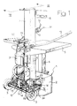
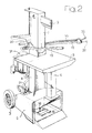
- the wood log splitting apparatus comprises a support structure generally designated as 1, formed by a base 2 possibly provided with wheels 3, a vertical hollow strut 4 and a horizontal bearing plate or platform 5 carried by a vertical column 6.
- the hollow strut 4 is open superiorly and houses in a telescopically slidable way a tubular element 7 from which a splitting blade or wedge 8, movable above the bearing platform 5, is projecting outwardly in a cantilever fashion.
- the splitting blade 8 is displaced perform such displacements, the splitting blade together with the tubular element 7 is carried by the stem 9 of a double-effect hydraulic jack 10 arranged vertically within the strut 4 and whose cylinder 11 is connected to the struct 4, such as clarified in the following, in an axially slidable way along a limited stroke of a predetermined amount.
- the arrangement could be reversed, i.e. the splitting blade 8 could be stationary and the bearing platform 5 would be accordingly displaceable with respect to the blade 8 by means of the jack 10.
- Reference numeral 12 indicates a valve unit, whose components shall be disclosed in more detail in the following, having a body 13 rigidly fixed to the base of the cylinder 11 of the hydraulic jack 10 by means of an attachment member 14, and provided with a direct operating member designated as 15.
- the direct operating member 15 is operatively connected both to a pedal 16 supported at the bottom of the strut 4 in a swingable way around a horizontal axis 17 and to which a return spring 18 is associated, and to a pair of swinging arms 19.
- the arms 19, mutually spaced apart are pivoted at opposite sides on top of the hollow strut 4 and are thus arranged above the bearing platform 5. It is however to be pointed out that this arrangement is purely indicative: the arms 19 might be replaced by simple levers or equivalent systems, even positioned beneath the bearing platform 5 or in any other apparatus area.
- the two arms 19 of the shown example may possibly be opened and closed relative to each other, arid are both connected to a rocker system generally indicated as 20 to operate, through a tie rod 21, the direct operating member 15 of the valve unit 12. This is such that the operating member 15 is actuated through the tie rod 21 only in case the arms 19 are both simultaneoously operated, for instance rotated downwardly, against the action of return springs 22 or other equivalent devices.
- the operating member 15 of the valve unit 12 can be aactuated either by the pedal 16, or by the two arms 19. In either case the operating member 15 is angularly shifted upwardly (or to the opposite direction) with respect to the inoperative position shown in the drawings, and in more detail in figures 3 and 5. It is however to be pointed out that the operative stroke of the two arms 19 for actuating the operating member 15 is greater than the corresponding operative stroke of the pedal 16, to which stop members 23, for instance consisting of screws, are to such effect associated.
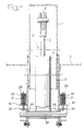
- the hydraulic jack 10 is not stationary, but is axially movable along a stroke of a predetermined amount with respect to the support structure 1 of the wood splitting apparatus.
- the cylinder 11 of the hydraulic jack 10 is fixed inferiorly to a horizontal transverse pin 24 whose ends are fitted in a vertically slidable way through respective lateral slots 25 of the hollow strut 4.
- Respective brackets 26 are secured onto these ends of the transverse pin 24, to each of which a vertical stem 27 is in turn fixed, carrying superiorly a plate 28.
- Helical compression springs 29 are interposed between the plates 28 and bearing members 30 secured laterally to the hollow strut 4.
- Figures 4 and 5 show the hydraulic jack 10 in its normal lowered position, in which the transverse pin 24 is arranged in correspondence of the lower portions of substantially balanced by the resilient thrust of the two springs 29, properly calibrated to this effect.
- Reference numeral 31 designates a pump of like source of hydraulic fluid under pressure, fixed to the support structure 1 of the splitting apparatus for operation, through the valve unit 12, or the hydraulic jack 10.
- the source 31 might also be provided at the outside of the splitting apparatus.
- Reference numeral 32 designates an auxiliary control member consisting of a swinging lever which, in the case of the shown example, is directly carried by the grasping end of one of the two swinging arms 19.
- the lever 32 (which might be replaced by any different but functionally equivalent actuating device) is oscillating between the raised position shown with continuous line in the drawings and the lowered position shown by dotted lines, and is connected by means of a transmission, for instance consisting of a flexible cable 33, to the body 13 of the valve unit 12.
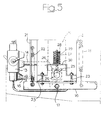
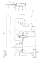
- valve unit 12 The construction of the valve unit 12 is depicted in the hydraulic circuit diagram of figure 6, and will now be disclosed in detail with reference to this figure.
- the valve unit 12 essentially comprises a main valve 34, consisting of a three-position distributor, whose displacement in one direction is operated by the against the action of the spring 12 or, respectively, of the springs 22.
- the inlet of the main valve 34 is connected with the delivery side of the source 31, which is also directly connected with the upper chamber 11a of the cylinder 11 of the hydraulic jack 10 through an outer regeneration line 42.
- Reference numeral 35 designates a secondary valve consisting of a two-position distributor.
- the secondary valve 35 is actuated by means of the control lever 32 and, in the raised position of such control lever 32 depicted with continuous line in the drawings, the secondary valve 35 is set in the open position shown in figure 6. In this position the secondary valve 35 opens, through a line 41, communication between a hydraulic self-piloting line 40 acting on the side of the main valve 34 opposite to the operating member 15; and a discharge 36.
- Calibrated check valves 37, 38 are provided in lines 40 and 41, respectively, and a pressure relief valve 39 is associated to the delivery side of the source 31, upstream of the main valve 34.
- the operator actuates starting of the splitting cycle, normally operating the pedal 16 thus being free to employ both hands to position and center more conveniently the log to be splitted.
- the main valve 34 opens communication between the lower chamber 11b at the cylinder 11 of the hydraulic jack 10, and the discharge 36.
- the main valve 34 opens communication between the pump 31 and the piloting line 40, which is however initially closed owing to calibration of the check valve 37, and which subsequently is connected to the discharge 36 through the secondary valve 35.
- the splitting blade 8 is thus moved downwardly until contacting the wood log to be splitted, or until it encounters a resistance to lowering thereof, for instance due to accidental contact of a finger or other parts of the operator's body against the splitting blade 8.
- both arms 19 In this condition, in order to start again displacement downwardly of the splitting blade 8 so as to carry out splitting of the wood log resting on the platform 5, both arms 19 must be operated, i.e. simultaneously rotated downwardly. This necessarily requires action of both operator's hands at least for a quite short period of time, which hands will in this phase be unable to hold the wood log to be splitted. However stability of the wood log onto the bearing platform 5 is warranted in this phase by the contrast force performed from above by the splitting blade 8.
- the auxiliary lever 32 enables instead to fully release the operator during the splitting stroke.
- the auxiliary lever 32 if upon initial downward displacement of the arms 19 the auxiliary lever 32 is shifted from the raised position to the lowered position shown with dotted lines in the drawings, closing of the secondary valve 35 is operated through the flexible transmission 33. Accordingly communication between the piloting line 40 and the discharge 36 is interrupted, whereby the main valve 34 is kept in the position set by means of the arms 19, due to the pressure within the piloting line 40.
- starting and completing of the splitting stroke of the blade 8 thus only requires that the operator performs a manoeuvre corresponding to one single impulse of the two arms 19, together with actuation of the auxiliary lever 32.
- the auxiliary lever 32 is brought again from the lowered position to the raised position shown with continuous line in the drawings, thus positioning again 11b of the cylinder 11, thus bringing the splitting blade 8 again to the raise starting position.
- the initial lowering phase of the splitting blade 8 from the raised position up to contact against the log to be splitting can also be operated, instead than through the pedal 16, by simultaneously actuation of the two arms 19, which however involves employing both operator's hands until the splitting blade 8 contacts the wood log to be splitted.
- the wood log splitting apparatus ensures the maximum safety degree against the risk of injuries, however with the advantage of providing during the actual splitting phase an automatic operation cycle, thus making the operator's hands available for instance to hold the wood logs when splitting is in progress, thus avoiding uncontrolled drop of the split pieces.
- piloting operated on the main valve 34 may be, instead of hydraulic, pneumatic or even electric in case the as in the case of the shown example, on top of the cylinder itself or even in correspondence of the connection between the stem 9 and the splitting blade 8.
- the valve unit 12 may also be not fixed to the cylinder 11 of the linear actuator 12, and be instead carried by the support structure of the apparatus and be connected to the cylinder through a transmission system operating the actuating member 15 in a way functionally equivalent to what has been previously disclosed by way of example.
Landscapes
- Engineering & Computer Science (AREA)
- Life Sciences & Earth Sciences (AREA)
- General Engineering & Computer Science (AREA)
- Wood Science & Technology (AREA)
- Forests & Forestry (AREA)
- Mechanical Engineering (AREA)
- Debarking, Splitting, And Disintegration Of Timber (AREA)
- Chemical And Physical Treatments For Wood And The Like (AREA)
- Manufacture Of Wood Veneers (AREA)
Priority Applications (1)
| Application Number | Priority Date | Filing Date | Title |
|---|---|---|---|
| SI9830478T SI0891845T1 (en) | 1997-07-11 | 1998-05-15 | Wood log or stub splitting apparatus |
Applications Claiming Priority (2)
| Application Number | Priority Date | Filing Date | Title |
|---|---|---|---|
| ITTO970625 | 1997-07-11 | ||
| IT97TO000625A IT1293440B1 (it) | 1997-07-11 | 1997-07-11 | Macchina spaccalegna o spaccatronchi. |
Publications (3)
| Publication Number | Publication Date |
|---|---|
| EP0891845A2 true EP0891845A2 (fr) | 1999-01-20 |
| EP0891845A3 EP0891845A3 (fr) | 2000-08-16 |
| EP0891845B1 EP0891845B1 (fr) | 2003-07-09 |
Family
ID=11415861
Family Applications (1)
| Application Number | Title | Priority Date | Filing Date |
|---|---|---|---|
| EP98830292A Expired - Lifetime EP0891845B1 (fr) | 1997-07-11 | 1998-05-15 | Dispositif pour fendre des pièces de bois |
Country Status (5)
| Country | Link |
|---|---|
| EP (1) | EP0891845B1 (fr) |
| AT (1) | ATE244625T1 (fr) |
| DE (1) | DE69816189T2 (fr) |
| IT (1) | IT1293440B1 (fr) |
| SI (1) | SI0891845T1 (fr) |
Cited By (4)
| Publication number | Priority date | Publication date | Assignee | Title |
|---|---|---|---|---|
| EP1852228A3 (fr) * | 2006-04-24 | 2008-10-29 | Ricca Andrea & C. S.n.c. | Machine pour couper le bois et fendre les bûches |
| WO2012167194A3 (fr) * | 2011-06-01 | 2013-03-28 | Blount, Inc. | Fendeuse de bûche avec des caractéristiques d'opération à deux mains |
| IT201800010050A1 (it) | 2018-11-05 | 2020-05-05 | Ricca Andrea & C S N C | Macchina spaccalegna o spaccatronchi |
| US12528223B2 (en) | 2022-08-26 | 2026-01-20 | Northern Tool & Equipment Company, Inc. | Battery-powered log splitter assembly and method thereof |
Family Cites Families (1)
| Publication number | Priority date | Publication date | Assignee | Title |
|---|---|---|---|---|
| DE9115379U1 (de) * | 1991-11-19 | 1992-03-26 | Mayer, Georg, 8261 Tittmoning | Vorrichtung zum maschinellen Spalten von Holz, insbesondere Brennholz |
-
1997
- 1997-07-11 IT IT97TO000625A patent/IT1293440B1/it active IP Right Grant
-
1998
- 1998-05-15 SI SI9830478T patent/SI0891845T1/xx unknown
- 1998-05-15 DE DE69816189T patent/DE69816189T2/de not_active Expired - Lifetime
- 1998-05-15 EP EP98830292A patent/EP0891845B1/fr not_active Expired - Lifetime
- 1998-05-15 AT AT98830292T patent/ATE244625T1/de active
Cited By (5)
| Publication number | Priority date | Publication date | Assignee | Title |
|---|---|---|---|---|
| EP1852228A3 (fr) * | 2006-04-24 | 2008-10-29 | Ricca Andrea & C. S.n.c. | Machine pour couper le bois et fendre les bûches |
| WO2012167194A3 (fr) * | 2011-06-01 | 2013-03-28 | Blount, Inc. | Fendeuse de bûche avec des caractéristiques d'opération à deux mains |
| IT201800010050A1 (it) | 2018-11-05 | 2020-05-05 | Ricca Andrea & C S N C | Macchina spaccalegna o spaccatronchi |
| EP3647006A1 (fr) | 2018-11-05 | 2020-05-06 | Ricca Andrea & C. S.n.c. | Appareil de fendage de bûches ou de chicots de bois |
| US12528223B2 (en) | 2022-08-26 | 2026-01-20 | Northern Tool & Equipment Company, Inc. | Battery-powered log splitter assembly and method thereof |
Also Published As
| Publication number | Publication date |
|---|---|
| IT1293440B1 (it) | 1999-03-01 |
| ITTO970625A1 (it) | 1999-01-11 |
| DE69816189T2 (de) | 2004-04-15 |
| DE69816189D1 (de) | 2003-08-14 |
| EP0891845A3 (fr) | 2000-08-16 |
| EP0891845B1 (fr) | 2003-07-09 |
| SI0891845T1 (en) | 2003-10-31 |
| ATE244625T1 (de) | 2003-07-15 |
Similar Documents
| Publication | Publication Date | Title |
|---|---|---|
| US4724554A (en) | Tilting patient treatment table having safety switch mat mechanism | |
| US20070262221A1 (en) | Industrial Truck | |
| EP0891845A2 (fr) | Dispositif pour fendre des pièces de bois | |
| CA1252426A (fr) | Methode de manoeuvre d'une fleche | |
| EP1852228B1 (fr) | Machine pour couper le bois et fendre les bûches | |
| EP0009974A1 (fr) | Circuit hydraulique pour colonne de pivotement | |
| US3986281A (en) | Safety system for pressers | |
| JP3211716B2 (ja) | 昇降部乗り込み型フォークリフト | |
| EP3647006B1 (fr) | Appareil de fendage de bûches ou de chicots de bois | |
| US5746291A (en) | Floor conveyor vehicle | |
| JP3418039B2 (ja) | 水田作業機 | |
| JPS608648Y2 (ja) | 昇降装置 | |
| EP0555198A1 (fr) | Dispositif de sécurité pour appareil destiné à lever et descendre des charges | |
| US4232519A (en) | Assisted braking device | |
| JPS5854902Y2 (ja) | 移動農機における油圧制御装置の油圧レバ−ガイド | |
| JP3011352B2 (ja) | 作業車のエンジン停止装置 | |
| JPH0826695A (ja) | オーダーピッカーの安全装置 | |
| EP3878796B1 (fr) | Appareil de levage pour l'entretien et la réparation de véhicules motorisés à deux roues | |
| JP3245332B2 (ja) | 水田作業車における機体昇降装置 | |
| JP3668218B2 (ja) | フットプレス機における安全補助装置 | |
| JPS6322810Y2 (fr) | ||
| JPH0620798Y2 (ja) | 高所作業車の安全装置 | |
| JPH0726909Y2 (ja) | 作業車輌におけるレバー装置 | |
| JPS624002Y2 (fr) | ||
| JPH0624443B2 (ja) | 作業機昇降制御装置 |
Legal Events
| Date | Code | Title | Description |
|---|---|---|---|
| PUAI | Public reference made under article 153(3) epc to a published international application that has entered the european phase |
Free format text: ORIGINAL CODE: 0009012 |
|
| AK | Designated contracting states |
Kind code of ref document: A2 Designated state(s): AT CH DE FR GB IT LI PT SE |
|
| AX | Request for extension of the european patent |
Free format text: AL;LT;LV;MK;RO;SI |
|
| PUAL | Search report despatched |
Free format text: ORIGINAL CODE: 0009013 |
|
| AK | Designated contracting states |
Kind code of ref document: A3 Designated state(s): AT BE CH CY DE DK ES FI FR GB GR IE IT LI LU MC NL PT SE |
|
| AX | Request for extension of the european patent |
Free format text: AL;LT;LV;MK;RO;SI |
|
| 17P | Request for examination filed |
Effective date: 20001118 |
|
| AKX | Designation fees paid |
Free format text: AT CH DE FR GB IT LI PT SE |
|
| AXX | Extension fees paid |
Free format text: SI PAYMENT 20001118 |
|
| 17Q | First examination report despatched |
Effective date: 20010913 |
|
| GRAH | Despatch of communication of intention to grant a patent |
Free format text: ORIGINAL CODE: EPIDOS IGRA |
|
| GRAH | Despatch of communication of intention to grant a patent |
Free format text: ORIGINAL CODE: EPIDOS IGRA |
|
| GRAA | (expected) grant |
Free format text: ORIGINAL CODE: 0009210 |
|
| AK | Designated contracting states |
Designated state(s): AT CH DE FR GB IT LI PT SE |
|
| AX | Request for extension of the european patent |
Extension state: SI |
|
| REG | Reference to a national code |
Ref country code: GB Ref legal event code: FG4D |
|
| REG | Reference to a national code |
Ref country code: CH Ref legal event code: NV Representative=s name: BRAUN & PARTNER PATENT-, MARKEN-, RECHTSANWAELTE Ref country code: CH Ref legal event code: EP |
|
| REF | Corresponds to: |
Ref document number: 69816189 Country of ref document: DE Date of ref document: 20030814 Kind code of ref document: P |
|
| PG25 | Lapsed in a contracting state [announced via postgrant information from national office to epo] |
Ref country code: SE Free format text: LAPSE BECAUSE OF FAILURE TO SUBMIT A TRANSLATION OF THE DESCRIPTION OR TO PAY THE FEE WITHIN THE PRESCRIBED TIME-LIMIT Effective date: 20031009 |
|
| PG25 | Lapsed in a contracting state [announced via postgrant information from national office to epo] |
Ref country code: PT Free format text: LAPSE BECAUSE OF FAILURE TO SUBMIT A TRANSLATION OF THE DESCRIPTION OR TO PAY THE FEE WITHIN THE PRESCRIBED TIME-LIMIT Effective date: 20031209 |
|
| PLBE | No opposition filed within time limit |
Free format text: ORIGINAL CODE: 0009261 |
|
| STAA | Information on the status of an ep patent application or granted ep patent |
Free format text: STATUS: NO OPPOSITION FILED WITHIN TIME LIMIT |
|
| ET | Fr: translation filed | ||
| 26N | No opposition filed |
Effective date: 20040414 |
|
| REG | Reference to a national code |
Ref country code: SI Ref legal event code: IF |
|
| PG25 | Lapsed in a contracting state [announced via postgrant information from national office to epo] |
Ref country code: IT Free format text: LAPSE BECAUSE OF NON-PAYMENT OF DUE FEES Effective date: 20090515 |
|
| PGRI | Patent reinstated in contracting state [announced from national office to epo] |
Ref country code: IT Effective date: 20110616 |
|
| PGFP | Annual fee paid to national office [announced via postgrant information from national office to epo] |
Ref country code: IT Payment date: 20110510 Year of fee payment: 14 |
|
| PG25 | Lapsed in a contracting state [announced via postgrant information from national office to epo] |
Ref country code: IT Free format text: LAPSE BECAUSE OF NON-PAYMENT OF DUE FEES Effective date: 20120515 |
|
| PGFP | Annual fee paid to national office [announced via postgrant information from national office to epo] |
Ref country code: AT Payment date: 20150427 Year of fee payment: 18 |
|
| REG | Reference to a national code |
Ref country code: FR Ref legal event code: PLFP Year of fee payment: 19 |
|
| REG | Reference to a national code |
Ref country code: AT Ref legal event code: MM01 Ref document number: 244625 Country of ref document: AT Kind code of ref document: T Effective date: 20160515 |
|
| PG25 | Lapsed in a contracting state [announced via postgrant information from national office to epo] |
Ref country code: AT Free format text: LAPSE BECAUSE OF NON-PAYMENT OF DUE FEES Effective date: 20160515 |
|
| REG | Reference to a national code |
Ref country code: SI Ref legal event code: KO00 Effective date: 20170216 |
|
| REG | Reference to a national code |
Ref country code: FR Ref legal event code: PLFP Year of fee payment: 20 |
|
| PGFP | Annual fee paid to national office [announced via postgrant information from national office to epo] |
Ref country code: CH Payment date: 20170529 Year of fee payment: 20 Ref country code: FR Payment date: 20170530 Year of fee payment: 20 Ref country code: GB Payment date: 20170530 Year of fee payment: 20 |
|
| PGFP | Annual fee paid to national office [announced via postgrant information from national office to epo] |
Ref country code: DE Payment date: 20170731 Year of fee payment: 20 |
|
| REG | Reference to a national code |
Ref country code: DE Ref legal event code: R071 Ref document number: 69816189 Country of ref document: DE Ref country code: CH Ref legal event code: PCAR Free format text: NEW ADDRESS: HOLEESTRASSE 87, 4054 BASEL (CH) |
|
| REG | Reference to a national code |
Ref country code: CH Ref legal event code: PL |
|
| REG | Reference to a national code |
Ref country code: GB Ref legal event code: PE20 Expiry date: 20180514 |
|
| PG25 | Lapsed in a contracting state [announced via postgrant information from national office to epo] |
Ref country code: GB Free format text: LAPSE BECAUSE OF EXPIRATION OF PROTECTION Effective date: 20180514 |