EP0891886B1 - Methode permettant a la carrosserie d'une voiture de supporter l'ensemble moteur et transmission et structure de support de l'ensemble - Google Patents
Methode permettant a la carrosserie d'une voiture de supporter l'ensemble moteur et transmission et structure de support de l'ensemble Download PDFInfo
- Publication number
- EP0891886B1 EP0891886B1 EP97917417A EP97917417A EP0891886B1 EP 0891886 B1 EP0891886 B1 EP 0891886B1 EP 97917417 A EP97917417 A EP 97917417A EP 97917417 A EP97917417 A EP 97917417A EP 0891886 B1 EP0891886 B1 EP 0891886B1
- Authority
- EP
- European Patent Office
- Prior art keywords
- mounts
- engine
- assembly
- vibration
- gravity
- Prior art date
- Legal status (The legal status is an assumption and is not a legal conclusion. Google has not performed a legal analysis and makes no representation as to the accuracy of the status listed.)
- Expired - Lifetime
Links
- 230000005540 biological transmission Effects 0.000 title claims description 23
- 238000000034 method Methods 0.000 title claims description 14
- 230000005484 gravity Effects 0.000 claims description 51
- 238000005096 rolling process Methods 0.000 claims description 8
- 238000005452 bending Methods 0.000 description 3
- 230000010485 coping Effects 0.000 description 3
- 230000033001 locomotion Effects 0.000 description 3
- 238000002485 combustion reaction Methods 0.000 description 2
- 230000001788 irregular Effects 0.000 description 2
- 239000011159 matrix material Substances 0.000 description 2
- 230000001133 acceleration Effects 0.000 description 1
- 238000011161 development Methods 0.000 description 1
- 230000018109 developmental process Effects 0.000 description 1
- 230000000694 effects Effects 0.000 description 1
- 230000002349 favourable effect Effects 0.000 description 1
- 230000014509 gene expression Effects 0.000 description 1
- 238000009434 installation Methods 0.000 description 1
- 230000035945 sensitivity Effects 0.000 description 1
Images


Classifications
-
- B—PERFORMING OPERATIONS; TRANSPORTING
- B60—VEHICLES IN GENERAL
- B60K—ARRANGEMENT OR MOUNTING OF PROPULSION UNITS OR OF TRANSMISSIONS IN VEHICLES; ARRANGEMENT OR MOUNTING OF PLURAL DIVERSE PRIME-MOVERS IN VEHICLES; AUXILIARY DRIVES FOR VEHICLES; INSTRUMENTATION OR DASHBOARDS FOR VEHICLES; ARRANGEMENTS IN CONNECTION WITH COOLING, AIR INTAKE, GAS EXHAUST OR FUEL SUPPLY OF PROPULSION UNITS IN VEHICLES
- B60K5/00—Arrangement or mounting of internal-combustion or jet-propulsion units
- B60K5/12—Arrangement of engine supports
- B60K5/1208—Resilient supports
- B60K5/1216—Resilient supports characterised by the location of the supports relative to the motor or to each other
-
- B—PERFORMING OPERATIONS; TRANSPORTING
- B60—VEHICLES IN GENERAL
- B60K—ARRANGEMENT OR MOUNTING OF PROPULSION UNITS OR OF TRANSMISSIONS IN VEHICLES; ARRANGEMENT OR MOUNTING OF PLURAL DIVERSE PRIME-MOVERS IN VEHICLES; AUXILIARY DRIVES FOR VEHICLES; INSTRUMENTATION OR DASHBOARDS FOR VEHICLES; ARRANGEMENTS IN CONNECTION WITH COOLING, AIR INTAKE, GAS EXHAUST OR FUEL SUPPLY OF PROPULSION UNITS IN VEHICLES
- B60K5/00—Arrangement or mounting of internal-combustion or jet-propulsion units
- B60K5/12—Arrangement of engine supports
-
- B—PERFORMING OPERATIONS; TRANSPORTING
- B60—VEHICLES IN GENERAL
- B60K—ARRANGEMENT OR MOUNTING OF PROPULSION UNITS OR OF TRANSMISSIONS IN VEHICLES; ARRANGEMENT OR MOUNTING OF PLURAL DIVERSE PRIME-MOVERS IN VEHICLES; AUXILIARY DRIVES FOR VEHICLES; INSTRUMENTATION OR DASHBOARDS FOR VEHICLES; ARRANGEMENTS IN CONNECTION WITH COOLING, AIR INTAKE, GAS EXHAUST OR FUEL SUPPLY OF PROPULSION UNITS IN VEHICLES
- B60K17/00—Arrangement or mounting of transmissions in vehicles
- B60K17/04—Arrangement or mounting of transmissions in vehicles characterised by arrangement, location or kind of gearing
- B60K17/06—Arrangement or mounting of transmissions in vehicles characterised by arrangement, location or kind of gearing of change-speed gearing
-
- F—MECHANICAL ENGINEERING; LIGHTING; HEATING; WEAPONS; BLASTING
- F16—ENGINEERING ELEMENTS AND UNITS; GENERAL MEASURES FOR PRODUCING AND MAINTAINING EFFECTIVE FUNCTIONING OF MACHINES OR INSTALLATIONS; THERMAL INSULATION IN GENERAL
- F16F—SPRINGS; SHOCK-ABSORBERS; MEANS FOR DAMPING VIBRATION
- F16F15/00—Suppression of vibrations in systems; Means or arrangements for avoiding or reducing out-of-balance forces, e.g. due to motion
- F16F15/02—Suppression of vibrations of non-rotating, e.g. reciprocating systems; Suppression of vibrations of rotating systems by use of members not moving with the rotating systems
- F16F15/04—Suppression of vibrations of non-rotating, e.g. reciprocating systems; Suppression of vibrations of rotating systems by use of members not moving with the rotating systems using elastic means
-
- B—PERFORMING OPERATIONS; TRANSPORTING
- B60—VEHICLES IN GENERAL
- B60K—ARRANGEMENT OR MOUNTING OF PROPULSION UNITS OR OF TRANSMISSIONS IN VEHICLES; ARRANGEMENT OR MOUNTING OF PLURAL DIVERSE PRIME-MOVERS IN VEHICLES; AUXILIARY DRIVES FOR VEHICLES; INSTRUMENTATION OR DASHBOARDS FOR VEHICLES; ARRANGEMENTS IN CONNECTION WITH COOLING, AIR INTAKE, GAS EXHAUST OR FUEL SUPPLY OF PROPULSION UNITS IN VEHICLES
- B60K5/00—Arrangement or mounting of internal-combustion or jet-propulsion units
- B60K5/04—Arrangement or mounting of internal-combustion or jet-propulsion units with the engine main axis, e.g. crankshaft axis, transversely to the longitudinal centre line of the vehicle
Definitions
- This invention relates to a method of supporting an assembly of an engine and a transmission of an automobile, in particular a passenger car, on a vehicle body and to a structure for supporting the assembly.
- a structure for supporting an assembly of an engine and a transmission of a passenger car on the vehicle body through a plurality of mounts there is a structure disclosed in document JP-U-63-133 408, wherein an equilateral triangle is imaged on a plane passing through the center of gravity of the engine and including a principal axis of inertia, the equilateral triangle having the center of gravity as its center and the structure having one side of the equilateral triangle disposed parallel to the principal axis of inertia, with the mounts placed in the neighborhood of the vertices of the equilateral triangle.
- a vibration phenomenon of an assembly of an engine and a transmission is greatly influenced by the characteristic value or the proper mode of the assembly, the characteristic value or the proper mode being determined by an item of inertia, the positions of the mounts and spring constants of the mounts.
- the characteristic value or the proper mode being determined by an item of inertia, the positions of the mounts and spring constants of the mounts.
- the vibration phenomenon caused to the assembly and means to cope with this vibration phenomenon are as follows: with respect to the vibration phenomenon of a low-frequency engine shake due to an irregular combustion, the upward and downward vibration of the engine and the vibration in the pitching direction of the engine respectively applied to the assembly are coupled; with respect to the engine wind-up vibration phenomenon caused at the time of acceleration and deceleration and a low-frequency idling vibration phenomenon due to an irregular combustion, the vibration in the width direction of the engine and the vibration in the rolling direction of the engine respectively applied to the assembly are not coupled and, furthermore, the vibration in the upward and downward direction of the engine and the vibration in the rolling direction of the engine respectively applied to the assembly are not coupled.
- the supporting structure described in the JP-A-59-167327 does not synthetically cope with the vibration phenomenon caused to the assembly.
- a method comprising the features of the pre-characterizing clause of claim 1 is known from document US-A-5 454 443.
- This document also discloses a structure of supporting an assembly of an engine and a transmission on a vehicle body by three mounts comprising the features of the pre-characterizing clause of claim 5.
- the mounts have a characteristic which determines a high natural frequency of the vibration in the rolling direction of the assembly and is modulated precisely to the torsion of the vehicle body and has a low stiffness of the mounts in the upward and downward direction.
- the first-mentioned object is achieved by the method according to claim 1.
- the three mounts are arranged in a plane passing through the center of gravity or its neighborhood so that the center of gravity of the assembly is positioned within a triangle formed by the three mounts.
- This arrangement can be deduced from a simplified model of vibration of three degrees of freedom, supposing two mounts and the center of gravity are within one plane and a rotational vibration about the center of gravity and a translating vibration are applied to the mounts.
- While five simultaneous equations are obtained from the three formulae recited in claim 1 there are more variables than these. Therefore, some binding conditions required for an automobile are to be given. For example, since the arrangement of the assembly of the engine and the transmission is determined physically by an engine room of a vehicle body and the positions of the mounts are determined substantially, it is possible to obtain from the three formulae recited in claim 1 how the spring constants of the mounts are preferably determined when these positions are maintained constant. On the contrary, it is possible to determine the positions of the mounts from the three formulae recited in claim 1 by giving such conditions as equalizing the spring constants of the three mounts respectively in the forward and backward direction and the width direction of the engine, or making the spring constants of all the mounts in the same direction constant.
- the center of gravity of the assembly is substantially within the same plane as the three mounts and within the triangle formed by the three mounts, requirements for restricting a generation of translation of the assembly are satisfied even if a rotating vibration about the center of gravity of the assembly occurs.
- requirements for the positions of the mounts and the spring constants to satisfy the matrix shown in Table 1 can be obtained. Thereby, the positions of the three mounts and the spring constants can be selected to be optimum.
- the spring constants of the three mounts can be made equal.
- a supporting structure with the positions and the spring constants of three or four mounts selected to be optimum can be provided.
- This supporting structure enables synthetically coping with the vibrations applied to the assembly when the assembly of the engine and the transmission is supported on the vehicle body.
- the assembly when to be installed in the front portion of the vehicle body such that the rotational axis of the crankshaft of the engine extends in the width direction of the vehicle body, is installed in the front portion of the vehicle body such that the principal axis of inertia extends in the width direction of the vehicle body. It becomes, therefore, possible to install the assembly in the neighborhood of a node of a bending mode of the vehicle body. This signifies that an input point of vibration from the engine to the vehicle body is a position where the vehicle body is hard to vibrate, and it is advantageous especially for idling vibration.
- the supporting structure of the present invention enables to synthetically cope with the vibrations applied to the assembly, but when the specific vibration is not sufficiently coped with, it is possible to take more effective measures against vibration by selecting the position of the plane passing through the center of gravity of the assembly. For example, when idling vibration is to be regarded as important, the plane is brought close to the vertical plane including the torque roll axis, while in other cases the plane is brought close to the vertical plane including the principal axis of inertia.
- three mounts each having spring functions in the forward and backward direction, the width direction, and the upward and downward direction of the engine are disposed in the plane passing through the center of gravity of the assembly or its neighborhood, and besides, the center of gravity is positioned in the triangle formed by the three mounts.
- the above-mentioned disposition of the center of gravity was obtained in the following manner.
- a vibration phenomenon, particularly a low frequency vibration phenomenon is greatly influenced by the characteristic value and the proper mode of the assembly, and the characteristic value and the proper mode are determined by an item of inertia of an engine, the positions of the mounts and the formula of the spring constant of the mounts.
- the item of inertia is given by the automobile, parameters are the positions of the mounts and the spring constants of the mounts. So, let's consider such a simplified model of three degrees of freedom as shown in Fig. 1.
- a vibration member 20 is supported by two mounts 22, 24, and the center of gravity G is in the center of the length 21 in the x direction and in h in the z direction to be rotationally vibrated upon receipt of torque T.
- the mounts 32, 34, 36 are placed on a plane PL and that the center of gravity G is placed within the triangle formed by the three mounts 32, 34, 36. It is, however, possible to place the neighborhood of the center of gravity on the plane PL in case the center of gravity G and the centers of the three mounts, respectively, cannot be strictly placed on the plane PL due to restrictions in placement and others.
- the two mounts 34, 36 may be placed below the center of gravity G with one mount 32 placed above the center of gravity G as shown in Fig. 5, or the two mounts 32, 34 may be placed above the center of gravity G with one mount 36 placed below the center of gravity G as shown in Fig. 6.
- a structure for supporting an assembly 30 by four mounts 38, 40, 42, 44 can be obtained. It is necessary that the four mounts 38, 40, 42, 44 be placed such that the center of gravity G of the assembly 30 and the respective centers of the four mounts 38, 40, 42, 44 are placed on the plane PL and, further, that the center of gravity G is placed within a quadrangle formed by the four mounts 38, 40, 42, 44. In such a case, an arrangement where the two mounts 38, 40 come above the center of gravity G while the two mounts 42, 44 come below the center of gravity G is convenient.
- the plane PL passing through the center of gravity G of the assembly 30 substantially coincides with the vertical plane including the principal axis of inertia of the engine.
- the assembly 30 be installed in the front portion of the vehicle body so that the rotational axis of the crankshaft of the engine may extend in the width direction WB of the vehicle body. It is a horizontal placement of the assembly 30, and when the vehicle body 50 is vibrated by such a bending mode 52 as shown in Fig. 9, the node 54 of vibration comes near the installation position of the assembly 30.
- the plane PL passing through the center of gravity G of the assembly 30 can be selected to be placed between the vertical plane including the principal axis 60 of inertia of the moment of inertia of the assembly 30 as viewed in the direction of the principal axis of inertia of the engine, that is, as viewed in the width direction WB in Fig. 8 and the vertical plane including the torque roll axis 62 of the assembly 30.
Landscapes
- Engineering & Computer Science (AREA)
- Mechanical Engineering (AREA)
- General Engineering & Computer Science (AREA)
- Chemical & Material Sciences (AREA)
- Combustion & Propulsion (AREA)
- Transportation (AREA)
- Physics & Mathematics (AREA)
- Acoustics & Sound (AREA)
- Aviation & Aerospace Engineering (AREA)
- Arrangement Or Mounting Of Propulsion Units For Vehicles (AREA)
- Vibration Prevention Devices (AREA)
Claims (12)
- Méthode pour supporter un ensemble (30) d'un moteur (26) et d'une transmission (28) sur une carrosserie de véhicule (50) en disposant trois montures (32, 34, 36) ayant chacune des fonctions de ressort suivant la direction vers l'avant et vers l'arrière (L), suivant la direction de largeur (W) et suivant la direction vers le haut et vers le bas (H) du dit moteur (26) dans un plan passant par le centre de gravité (G) du dit ensemble (30) ou par son voisinage, et en plaçant le dit centre de gravité (G) dans le triangle formé par les dites trois montures pour supporter le dit ensemble (30), caractérisée par
la détermination des positions des dites trois montures (32, 34, 36) et des constantes de rappel de manière qu'elles satisfassent aux trois formules suivantes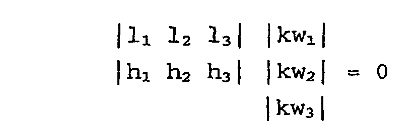
 où les positions des dites trois montures (32, 34, 36) par rapport au dit centre de gravité (G) suivant la direction vers l'avant et vers l'arrière (L), suivant la direction de largeur (W) et suivant la direction vers le haut et vers le bas (H) du moteur (26) sont respectivement fixées pour être l1, w1, h1, l2, w2, h2, l3, w3, h3, et les constantes de rappel suivant la direction vers l'avant et vers l'arrière (L), suivant la direction de largeur (W) et suivant la direction vers le haut et vers le bas (H) du moteur (26) sont respectivement fixées pour être kl1, kw1, kh1, kl2, kw2, kh2, kl3, kw3, kh3.
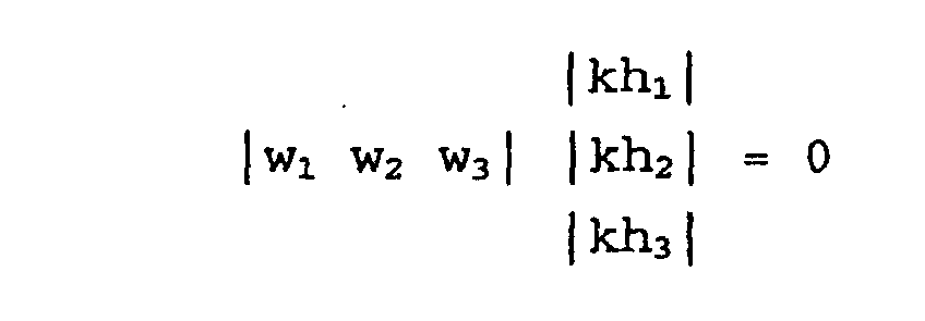
- Méthode selon la revendication 1, dans laquelle les dites trois montures (32, 34, 36) sont disposées dans des positions qui satisfont simultanément à
- Méthode selon la revendication 1, dans laquelle les positions respectives des dites trois montures (32, 34, 36) sont déterminées préférentiellement, sur la base de laquelle sont déterminées les constantes de rappel des dites trois montures.
- Méthode selon la revendication 1, dans Laquelle les constantes de rappel des dites trois montures (32, 34, 36) sont déterminées préférentiellement, sur la base de laquelle sont déterminées les positions des dites trois montures.
- Structure pour supporter un ensemble (30) d'un moteur (26) et d'une transmission (28) sur une carrosserie de véhicule (50) au moyen de trois ou quatre montures (32, 34, 36 ; 38, 40, 42, 44) ayant chacune des fonctions de ressort suivant la direction vers l'avant et vers l'arrière (L), suivant la direction de largeur (W) et suivant la direction vers le haut et vers le bas (H) du moteur (26), dans laquelle les dites montures sont disposées dans un plan (PL) passant par le centre de gravité (G) du dit ensemble (30) ou par son voisinage, de telle sorte qu'un triangle ou un quadrilatère formé par les montures circonscrive le centre de gravité (G) du dit ensemble (30), caractérisée en ce que les positions et les constantes de rappel des dites montures (32, 34, 36 ; 38, 40, 42, 44) sont déterminées de telle sorte que les vibrations suivant la direction vers l'avant et vers l'arrière (L) du moteur (26) appliquées sur les dites montures, et les vibrations suivant la direction de tangage (P) du moteur (26) appliquées sur les dites montures ne sont pas couplées ; les vibrations suivant la direction vers l'avant et vers l'arrière (L) du moteur (26) appliquées sur les dites montures, et les vibrations suivant la direction de lacet (Y) du moteur (26) appliquées sur les dites montures ne sont pas couplées ; les vibrations suivant la direction de largeur (W) du moteur (26) appliquées sur les dites montures, et les vibrations suivant la direction de roulis (R) du moteur (26) appliquées sur les dites montures ne sont pas couplées ; les vibrations suivant la direction de largeur (W) du moteur (26) appliquées sur les dites montures, et les vibrations suivant la direction de lacet (Y) du moteur (26) appliquées sur les dites montures ne sont pas couplées ; les vibrations suivant la direction vers le haut et vers le bas (H) du moteur (26) appliquées sur les dites montures, et les vibrations suivant la direction de tangage (P) du moteur (26) appliquées sur les dites montures sont couplées ; et les vibrations suivant la direction vers le haut et vers le bas (H) du moteur (26) appliquées sur les dites montures, et vibrations suivant la direction de roulis (R) du moteur (26) appliquées sur les dites montures ne sont pas couplées.
- Structure selon la revendication 5, dans laquelle le dit plan (PL) passant par le centre de gravité (G) du dit ensemble (30) ou par son voisinage coïncide sensiblement avec un plan vertical incluant l'axe principal d'inertie (60) du dit moteur (26).
- Structure selon la revendication 6, dans laquelle le dit ensemble (30) est installé dans la partie avant de la carrosserie de véhicule (50) de telle sorte que l'axe de rotation d'un vilebrequin s'étend suivant la direction de largeur (WB) de la carrosserie de véhicule.
- Structure selon la revendication 5, dans laquelle le dit plan (PL) passant par le centre de gravité (G) du dit ensemble (30) ou par son voisinage est sélectionné pour être placé entre un plan vertical incluant l'axe principal d'inertie (60) du moment d'inertie du dit ensemble (30) en regardant suivant la direction de l'axe principal d'inertie du dit moteur (26) et un plan vertical incluant l'axe de roulis de couple (52) du dit ensemble.
- Structure selon la revendication 5, dans laquelle le nombre des dites montures (32, 34, 36) est de trois.
- Structure selon la revendication 9, dans laquelle deux des dites trois montures (32, 34, 36) sont placées au-dessus du dit centre de gravité (G), celle restante étant placée au-dessous du dit centre de gravité (G).
- Structure selon la revendication 9, dans laquelle deux des dites trois montures (32, 34, 36) sont placées au-dessous du dit centre de gravité (G), celle restante étant placée au-dessus du dit centre de gravité (G).
- Structure selon la revendication 5, dans laquelle le nombre des dites montures (38, 40, 42, 44) est de quatre, dont deux sont placées au-dessus du dit centre de gravité (G), les deux autres étant placées au-dessous du dit centre de gravité (G).
Applications Claiming Priority (4)
| Application Number | Priority Date | Filing Date | Title |
|---|---|---|---|
| JP12398296 | 1996-04-23 | ||
| JP12398296A JP3374655B2 (ja) | 1996-04-23 | 1996-04-23 | エンジンとトランスミッションとの組立体を車体に支持する方法および組立体の支持構造 |
| JP123982/96 | 1996-04-23 | ||
| PCT/JP1997/001328 WO1997039908A1 (fr) | 1996-04-23 | 1997-04-17 | Methode permettant a la carrosserie d'une voiture de supporter l'ensemble moteur et transmission et structure de support de l'ensemble |
Publications (3)
| Publication Number | Publication Date |
|---|---|
| EP0891886A1 EP0891886A1 (fr) | 1999-01-20 |
| EP0891886A4 EP0891886A4 (fr) | 2000-05-17 |
| EP0891886B1 true EP0891886B1 (fr) | 2002-06-26 |
Family
ID=14874122
Family Applications (1)
| Application Number | Title | Priority Date | Filing Date |
|---|---|---|---|
| EP97917417A Expired - Lifetime EP0891886B1 (fr) | 1996-04-23 | 1997-04-17 | Methode permettant a la carrosserie d'une voiture de supporter l'ensemble moteur et transmission et structure de support de l'ensemble |
Country Status (8)
| Country | Link |
|---|---|
| EP (1) | EP0891886B1 (fr) |
| JP (1) | JP3374655B2 (fr) |
| KR (1) | KR100286199B1 (fr) |
| CN (1) | CN1066106C (fr) |
| AU (1) | AU709632B2 (fr) |
| CA (1) | CA2249311A1 (fr) |
| DE (1) | DE69713579T2 (fr) |
| WO (1) | WO1997039908A1 (fr) |
Cited By (2)
| Publication number | Priority date | Publication date | Assignee | Title |
|---|---|---|---|---|
| WO2022258389A1 (fr) * | 2021-06-10 | 2022-12-15 | Bayerische Motoren Werke Aktiengesellschaft | Ensemble palier pour le montage d'un groupe d'un véhicule automobile sur un composant structural du véhicule automobile |
| US12196285B2 (en) | 2021-06-10 | 2025-01-14 | Bayerische Motoren Werke Aktiengesellschaft | Bearing assembly for supporting a unit of a motor vehicle on a structural component of the motor vehicle |
Families Citing this family (14)
| Publication number | Priority date | Publication date | Assignee | Title |
|---|---|---|---|---|
| SE522426C2 (sv) | 2001-06-08 | 2004-02-10 | Scania Cv Ab | Upphängningsarrangemang för drivaggregat vid motorfordon |
| DE10200311A1 (de) * | 2002-01-07 | 2003-07-24 | Freudenberg Carl Kg | Lagerung für eine Motor- und/oder Getriebeeinheit |
| EP1580057B1 (fr) * | 2004-03-24 | 2013-04-24 | Nissan Motor Company Limited | Dispositif et méthode de support d'un train de propulsion de véhicule automobile |
| FR2884210B1 (fr) * | 2005-04-12 | 2007-06-15 | Hutchinson Sa | Dispositif de suspension d'un moteur sur un chassis de bogie |
| US20070107971A1 (en) * | 2005-10-28 | 2007-05-17 | Mazda Motor Corporation | Product designing system and method, and computer-readable recording medium having product designing program recorded thereon |
| JP2007139080A (ja) * | 2005-11-18 | 2007-06-07 | Bridgestone Corp | 防振支持構造 |
| JP4923898B2 (ja) * | 2006-09-15 | 2012-04-25 | 日産自動車株式会社 | マウントシステム |
| RU2505424C1 (ru) * | 2009-11-26 | 2014-01-27 | Ниссан Мотор Ко., Лтд. | Трехцилиндровый двигатель |
| FR2966784B1 (fr) * | 2010-10-28 | 2012-12-14 | Peugeot Citroen Automobiles Sa | Ensemble de suspension d'un organe generateur de vibrations embarque dans un vehicule automobile |
| JP2016078622A (ja) * | 2014-10-16 | 2016-05-16 | マツダ株式会社 | 自動車の発動発電機搭載構造 |
| JP6616122B2 (ja) * | 2015-08-07 | 2019-12-04 | 株式会社ブリヂストン | エンジン装置支持構造、及び、エンジン装置設置方法 |
| GB2543796B (en) * | 2015-10-28 | 2018-06-06 | Ford Global Tech Llc | A powertrain mount assembly for a motor vehicle |
| JP6288656B2 (ja) * | 2016-07-25 | 2018-03-07 | 国立研究開発法人宇宙航空研究開発機構 | 振動アイソレータの共振周波数の調整方法及び調整システム、振動アイソレータ、並びに振動アイソレータの設計方法、設計システム、及び製造方法 |
| CN109764083B (zh) * | 2019-01-25 | 2025-02-18 | 福建侨龙应急装备股份有限公司 | 一种车载设备减震装置及设备运载车 |
Family Cites Families (4)
| Publication number | Priority date | Publication date | Assignee | Title |
|---|---|---|---|---|
| JPS59167327A (ja) * | 1983-03-14 | 1984-09-20 | Toyota Motor Corp | 車輌に於けるエンジン−トランスミツシヨン組立体の支持構造 |
| DE3638504A1 (de) * | 1986-11-11 | 1988-05-26 | Sds Relais Ag | Elektrische kontaktvorrichtung |
| JPS63133408U (fr) * | 1987-02-24 | 1988-08-31 | ||
| DE4307999A1 (de) * | 1993-03-13 | 1994-09-15 | Porsche Ag | Kraftfahrzeug |
-
1996
- 1996-04-23 JP JP12398296A patent/JP3374655B2/ja not_active Expired - Fee Related
-
1997
- 1997-04-17 WO PCT/JP1997/001328 patent/WO1997039908A1/fr not_active Ceased
- 1997-04-17 DE DE69713579T patent/DE69713579T2/de not_active Expired - Lifetime
- 1997-04-17 CA CA002249311A patent/CA2249311A1/fr not_active Abandoned
- 1997-04-17 EP EP97917417A patent/EP0891886B1/fr not_active Expired - Lifetime
- 1997-04-17 CN CN97194083A patent/CN1066106C/zh not_active Expired - Fee Related
- 1997-04-17 AU AU25760/97A patent/AU709632B2/en not_active Ceased
- 1997-04-17 KR KR1019980708398A patent/KR100286199B1/ko not_active Expired - Fee Related
Cited By (3)
| Publication number | Priority date | Publication date | Assignee | Title |
|---|---|---|---|---|
| WO2022258389A1 (fr) * | 2021-06-10 | 2022-12-15 | Bayerische Motoren Werke Aktiengesellschaft | Ensemble palier pour le montage d'un groupe d'un véhicule automobile sur un composant structural du véhicule automobile |
| US12196285B2 (en) | 2021-06-10 | 2025-01-14 | Bayerische Motoren Werke Aktiengesellschaft | Bearing assembly for supporting a unit of a motor vehicle on a structural component of the motor vehicle |
| US12358348B2 (en) | 2021-06-10 | 2025-07-15 | Bayerische Motoren Werke Aktiengesellschaft | Bearing assembly for supporting a unit of a motor vehicle on a structural component of the motor vehicle |
Also Published As
| Publication number | Publication date |
|---|---|
| WO1997039908A1 (fr) | 1997-10-30 |
| DE69713579T2 (de) | 2002-11-21 |
| DE69713579D1 (de) | 2002-08-01 |
| KR20000010551A (ko) | 2000-02-15 |
| AU2576097A (en) | 1997-11-12 |
| CN1066106C (zh) | 2001-05-23 |
| CA2249311A1 (fr) | 1997-10-30 |
| CN1216504A (zh) | 1999-05-12 |
| JP3374655B2 (ja) | 2003-02-10 |
| EP0891886A1 (fr) | 1999-01-20 |
| JPH09286244A (ja) | 1997-11-04 |
| EP0891886A4 (fr) | 2000-05-17 |
| KR100286199B1 (ko) | 2001-06-01 |
| AU709632B2 (en) | 1999-09-02 |
Similar Documents
| Publication | Publication Date | Title |
|---|---|---|
| EP0891886B1 (fr) | Methode permettant a la carrosserie d'une voiture de supporter l'ensemble moteur et transmission et structure de support de l'ensemble | |
| EP0890468B1 (fr) | Système de suspension pour un groupe d'entraínement | |
| EP0052291B1 (fr) | Système d'absorption de vibrations pour véhicule automobile | |
| JP2657319B2 (ja) | 自動車のパワーユニット支持装置 | |
| JPS616020A (ja) | 自動車の振動吸収装置 | |
| JPH1111159A (ja) | 車両用エンジンの懸架装置 | |
| CA2225329A1 (fr) | Systeme hydraulique d'amortissement de couple | |
| JP3645940B2 (ja) | パワーユニットのマウント装置 | |
| JPS6340679Y2 (fr) | ||
| JPH01226429A (ja) | 車両用パワープラントのマウント構造 | |
| JPH05330347A (ja) | パワープラントのマウント構造 | |
| JP2596062Y2 (ja) | 自動車のパワユニット支持構造 | |
| JPH0574489B2 (fr) | ||
| JPS624014Y2 (fr) | ||
| CN223919111U (zh) | 一种十字调节的商用车进气道上支架结构 | |
| JPS6322093Y2 (fr) | ||
| JPH09226385A (ja) | エンジンマウント | |
| JPS6264622A (ja) | パワ−ユニツトの支持装置 | |
| JP2511303Y2 (ja) | 車両のパワ―ユニット支持装置 | |
| JP3216290B2 (ja) | フットレストの防振構造 | |
| JPH07117493A (ja) | 車両用パワープラント支持装置 | |
| JPH08192641A (ja) | 車両用エンジンのマウント装置 | |
| JP2000266123A (ja) | ミッションマウント装置 | |
| JPS6137508A (ja) | 自動車のリヤサスペンシヨン装置 | |
| JPH11198869A (ja) | スペアタイヤ支持方法およびこの方法を用いたスペアタイヤ収納部 |
Legal Events
| Date | Code | Title | Description |
|---|---|---|---|
| PUAI | Public reference made under article 153(3) epc to a published international application that has entered the european phase |
Free format text: ORIGINAL CODE: 0009012 |
|
| 17P | Request for examination filed |
Effective date: 19980923 |
|
| AK | Designated contracting states |
Kind code of ref document: A1 Designated state(s): DE FR GB |
|
| A4 | Supplementary search report drawn up and despatched |
Effective date: 20000405 |
|
| AK | Designated contracting states |
Kind code of ref document: A4 Designated state(s): DE FR GB |
|
| 17Q | First examination report despatched |
Effective date: 20000908 |
|
| GRAG | Despatch of communication of intention to grant |
Free format text: ORIGINAL CODE: EPIDOS AGRA |
|
| GRAG | Despatch of communication of intention to grant |
Free format text: ORIGINAL CODE: EPIDOS AGRA |
|
| GRAH | Despatch of communication of intention to grant a patent |
Free format text: ORIGINAL CODE: EPIDOS IGRA |
|
| GRAH | Despatch of communication of intention to grant a patent |
Free format text: ORIGINAL CODE: EPIDOS IGRA |
|
| GRAA | (expected) grant |
Free format text: ORIGINAL CODE: 0009210 |
|
| AK | Designated contracting states |
Kind code of ref document: B1 Designated state(s): DE FR GB |
|
| REG | Reference to a national code |
Ref country code: GB Ref legal event code: FG4D |
|
| REF | Corresponds to: |
Ref document number: 69713579 Country of ref document: DE Date of ref document: 20020801 |
|
| ET | Fr: translation filed | ||
| PLBE | No opposition filed within time limit |
Free format text: ORIGINAL CODE: 0009261 |
|
| STAA | Information on the status of an ep patent application or granted ep patent |
Free format text: STATUS: NO OPPOSITION FILED WITHIN TIME LIMIT |
|
| 26N | No opposition filed |
Effective date: 20030327 |
|
| REG | Reference to a national code |
Ref country code: GB Ref legal event code: 746 Effective date: 20050707 |
|
| REG | Reference to a national code |
Ref country code: FR Ref legal event code: D6 |
|
| PGFP | Annual fee paid to national office [announced via postgrant information from national office to epo] |
Ref country code: DE Payment date: 20110413 Year of fee payment: 15 Ref country code: FR Payment date: 20110426 Year of fee payment: 15 |
|
| PGFP | Annual fee paid to national office [announced via postgrant information from national office to epo] |
Ref country code: GB Payment date: 20110413 Year of fee payment: 15 |
|
| GBPC | Gb: european patent ceased through non-payment of renewal fee |
Effective date: 20120417 |
|
| REG | Reference to a national code |
Ref country code: FR Ref legal event code: ST Effective date: 20121228 |
|
| PG25 | Lapsed in a contracting state [announced via postgrant information from national office to epo] |
Ref country code: GB Free format text: LAPSE BECAUSE OF NON-PAYMENT OF DUE FEES Effective date: 20120417 |
|
| REG | Reference to a national code |
Ref country code: DE Ref legal event code: R119 Ref document number: 69713579 Country of ref document: DE Effective date: 20121101 |
|
| PG25 | Lapsed in a contracting state [announced via postgrant information from national office to epo] |
Ref country code: FR Free format text: LAPSE BECAUSE OF NON-PAYMENT OF DUE FEES Effective date: 20120430 |
|
| PG25 | Lapsed in a contracting state [announced via postgrant information from national office to epo] |
Ref country code: DE Free format text: LAPSE BECAUSE OF NON-PAYMENT OF DUE FEES Effective date: 20121101 |