EP0892229B1 - Appareil à circulation de liquide isotherme - Google Patents
Appareil à circulation de liquide isotherme Download PDFInfo
- Publication number
- EP0892229B1 EP0892229B1 EP98305204A EP98305204A EP0892229B1 EP 0892229 B1 EP0892229 B1 EP 0892229B1 EP 98305204 A EP98305204 A EP 98305204A EP 98305204 A EP98305204 A EP 98305204A EP 0892229 B1 EP0892229 B1 EP 0892229B1
- Authority
- EP
- European Patent Office
- Prior art keywords
- isothermal
- units
- circulating
- unit
- refrigerant liquid
- Prior art date
- Legal status (The legal status is an assumption and is not a legal conclusion. Google has not performed a legal analysis and makes no representation as to the accuracy of the status listed.)
- Expired - Lifetime
Links
- 239000007788 liquid Substances 0.000 title claims description 51
- 239000003507 refrigerant Substances 0.000 claims description 36
- 238000001816 cooling Methods 0.000 claims description 22
- 238000010438 heat treatment Methods 0.000 claims description 6
- 230000004913 activation Effects 0.000 claims description 4
- 239000000758 substrate Substances 0.000 description 9
- 238000004519 manufacturing process Methods 0.000 description 6
- 230000007257 malfunction Effects 0.000 description 5
- 230000002950 deficient Effects 0.000 description 4
- 230000007547 defect Effects 0.000 description 3
- 230000002265 prevention Effects 0.000 description 3
- 238000012423 maintenance Methods 0.000 description 2
- 230000008439 repair process Effects 0.000 description 2
- 239000004065 semiconductor Substances 0.000 description 2
- 238000010586 diagram Methods 0.000 description 1
- 238000011144 upstream manufacturing Methods 0.000 description 1
Images
Classifications
-
- B—PERFORMING OPERATIONS; TRANSPORTING
- B23—MACHINE TOOLS; METAL-WORKING NOT OTHERWISE PROVIDED FOR
- B23Q—DETAILS, COMPONENTS, OR ACCESSORIES FOR MACHINE TOOLS, e.g. ARRANGEMENTS FOR COPYING OR CONTROLLING; MACHINE TOOLS IN GENERAL CHARACTERISED BY THE CONSTRUCTION OF PARTICULAR DETAILS OR COMPONENTS; COMBINATIONS OR ASSOCIATIONS OF METAL-WORKING MACHINES, NOT DIRECTED TO A PARTICULAR RESULT
- B23Q11/00—Accessories fitted to machine tools for keeping tools or parts of the machine in good working condition or for cooling work; Safety devices specially combined with or arranged in, or specially adapted for use in connection with, machine tools
- B23Q11/14—Methods or arrangements for maintaining a constant temperature in parts of machine tools
- B23Q11/143—Methods or arrangements for maintaining a constant temperature in parts of machine tools comprising heating means
-
- B—PERFORMING OPERATIONS; TRANSPORTING
- B23—MACHINE TOOLS; METAL-WORKING NOT OTHERWISE PROVIDED FOR
- B23Q—DETAILS, COMPONENTS, OR ACCESSORIES FOR MACHINE TOOLS, e.g. ARRANGEMENTS FOR COPYING OR CONTROLLING; MACHINE TOOLS IN GENERAL CHARACTERISED BY THE CONSTRUCTION OF PARTICULAR DETAILS OR COMPONENTS; COMBINATIONS OR ASSOCIATIONS OF METAL-WORKING MACHINES, NOT DIRECTED TO A PARTICULAR RESULT
- B23Q11/00—Accessories fitted to machine tools for keeping tools or parts of the machine in good working condition or for cooling work; Safety devices specially combined with or arranged in, or specially adapted for use in connection with, machine tools
- B23Q11/14—Methods or arrangements for maintaining a constant temperature in parts of machine tools
- B23Q11/141—Methods or arrangements for maintaining a constant temperature in parts of machine tools using a closed fluid circuit for cooling or heating
-
- F—MECHANICAL ENGINEERING; LIGHTING; HEATING; WEAPONS; BLASTING
- F25—REFRIGERATION OR COOLING; COMBINED HEATING AND REFRIGERATION SYSTEMS; HEAT PUMP SYSTEMS; MANUFACTURE OR STORAGE OF ICE; LIQUEFACTION SOLIDIFICATION OF GASES
- F25D—REFRIGERATORS; COLD ROOMS; ICE-BOXES; COOLING OR FREEZING APPARATUS NOT OTHERWISE PROVIDED FOR
- F25D17/00—Arrangements for circulating cooling fluids; Arrangements for circulating gas, e.g. air, within refrigerated spaces
- F25D17/02—Arrangements for circulating cooling fluids; Arrangements for circulating gas, e.g. air, within refrigerated spaces for circulating liquids, e.g. brine
-
- F—MECHANICAL ENGINEERING; LIGHTING; HEATING; WEAPONS; BLASTING
- F25—REFRIGERATION OR COOLING; COMBINED HEATING AND REFRIGERATION SYSTEMS; HEAT PUMP SYSTEMS; MANUFACTURE OR STORAGE OF ICE; LIQUEFACTION SOLIDIFICATION OF GASES
- F25B—REFRIGERATION MACHINES, PLANTS OR SYSTEMS; COMBINED HEATING AND REFRIGERATION SYSTEMS; HEAT PUMP SYSTEMS
- F25B41/00—Fluid-circulation arrangements
- F25B41/20—Disposition of valves, e.g. of on-off valves or flow control valves
Definitions
- the present invention relates to an isothermal-liquid circulating apparatus for supplying an isothermal refrigerant liquid to mechanical apparatuses having an isothermal section and used in various industrial fields, and in particular, to an isothermal-liquid circulating apparatus all components of which are integrated into units.
- Various mechanical apparatuses having an isothermal portion e.g., semiconductor fabrication apparatuses, require an isothermal refrigerant liquid to be continuously supplied to the isothermal portion (a load) in order to maintain the load at a predetermined temperature.
- such apparatuses include an isothermal-liquid circulating apparatus that supplies an isothermal refrigerant liquid.
- the refrigerant liquid the temperature of which has been increased by the load, is returned to the isothermal-liquid circulating apparatus, where the liquid is cooled by a heat exchanger, then heated by a heater to a predetermined temperature, and then circularly supplied to the load (see for intance US-A-4 729 424).
- such an isothermal-liquid circulating apparatus is employed in semiconductor fabrication apparatuses but also in mechanical apparatuses used in various industrial fields that require the temperature to be controlled, in order to support the operations of these apparatuses. Consequently, a defect in the isothermal-liquid circulating apparatus or its malfunction may cause the mechanical apparatus to be stopped, resulting in large losses. Thus, it is necessary to prevent defects and malfunctions. If any defect or malfunction occurs, the apparatus must be returned to its normal operational conditions as promptly as possible.
- this invention provides an isothermal-liquid circulating apparatus for circulating and supplying an isothermal refrigerant liquid to a load, as defined in claim 1.
- Said apparatus comprises a cooling circuit section for cooling in a heat exchanger the refrigerant liquid returned from the load; a circulating circuit section for heating to a predetermined temperature the refrigerant liquid cooled by the heat exchanger and then delivering it; and equipment for operating these sections. All components of the apparatus that function independently are integrated into units that are independently and detachably mounted on a frame. Connectors provided on the respective units for electric wiring connections are detachably connected to a relay substrate mounted on the frame, the units being electrically connected together via the relay substrate.
- the units include a cooling and circulating unit comprising the cooling circuit section for cooling in a heat exchanger the refrigerant liquid returned from the load and the circulating circuit section for heating to a predetermined temperature the refrigerant liquid cooled by the heat exchanger and then delivering it; an input/display unit including an activation switch, a temperature setting device for setting the temperature of the refrigerant liquid, and an operation display device; a control section unit comprising a sequencer; and an electrical section unit including various electrical parts.
- the component units that function independently i.e., the cooling and circulating unit, input/display unit, control section unit, and electrical section unit are independently and detachably mounted on the frame.
- the cooling and circulating unit, input/display unit, control section unit, and electrical section unit are independently and detachably mounted on the frame.
- this invention significantly improves the maintainability of the isothermal-liquid circulating apparatus while substantially reducing the number of assembly steps required during manufacturing.
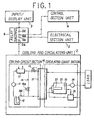
- FIGS. 1 and 2 show an embodiment of an isothermal-liquid circulating apparatus according to this invention.
- This isothermal-liquid circulating apparatus essentially circulates and continuously supplies an isothermal refrigerant liquid to an isothermal section (a load) in various mechanical apparatuses, and mainly comprises a cooling circuit section for cooling in a heat exchanger the refrigerant liquid returned from the load; a circulating circuit section for heating to a predetermined temperature the refrigerant liquid cooled by the heat exchanger and then delivering it; and various equipment for operating these sections.
- the isothermal-liquid circulating apparatus is configured so that the main components, which function independently, are integrated into units and so that the apparatus includes a frame 1 on which the units are independ ently and detachably mounted as shown in FIG. 1.
- the units of the main components function independently as described above and are integrated into units in such a way that the units can be mutually connected to other units using only electric wiring. Specifically, as illustrated in FIGS.
- the units of the main components are appropriately composed of a cooling and circulating unit 2 comprising the cooling circuit section for cooling in a heat exchanger the refrigerant liquid returned from the load and the circulating circuit section for heating to a predetermined temperature the refrigerant liquid cooled by the heat exchanger and then delivering it; an input/display unit 3 in cluding an activation switch, a temperature setting device for setting the temperature of the refrigerant liquid, and an operation display device for displaying the current operational conditions; a control section unit 4 comprising a sequencer that provides a series of operations and controls; and an electrical section unit 5 including various electrical parts.
- the units 2 to 5 of the components that are integrated into units are configured so as to be independently and detachably mounted on the frame 1.
- the "independent and detachable mounting” means that any unit can be independently installed on and removed from any part of the frame 1 using mounting means such as bolts (not shown) and without the need to remove other units.
- covers can be installed as required on those parts of the frame 1 on which the units are mounted.
- the covers constitute part of the frame 1, so smaller units can be attached to these covers.
- connectors are provided on the respective units 2 to 5 for electric wiring connection so as to be detachably connected to connectors 2a to 5a on the relay substrate 6 independently mounted on the frame 1. Accordingly, the connection of the units 2 to 5 to a power supply and the connection of electric signal lines among the units can be established via the relay substrate 6.
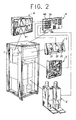
- the cooling and circulating unit 2 comprises the cooling circuit section for cooling in the heat exchanger the refrigerant liquid the temperature of which has been increased by the load; and the circulating circuit section for heating to a predetermined temperature the refrigerant liquid cooled by the heat exchanger and then delivering it, as shown in FIG. 2.
- the cooling circuit section generally comprises a compressor 11 that compresses the refrigerant into a hot and highly pressurized gas; a condenser 12 that cools and condenses the gas into a highly pressurized refrigerant (liquid); a pressure-reducing device (a pressure-reducing valve) 13 that reduces the pressure of the refrigerant; an evaporator 14 that evaporates the refrigerant with its pressure reduced in order to reduce the temperature; and an accumulator 15, all of which are connected in series.
- a compressor 11 that compresses the refrigerant into a hot and highly pressurized gas
- a condenser 12 that cools and condenses the gas into a highly pressurized refrigerant (liquid)
- a pressure-reducing device a pressure-reducing valve 13 that reduces the pressure of the refrigerant
- an evaporator 14 that evaporates the refrigerant with its pressure reduced in order to reduce the temperature
- an accumulator 15 all of which are connected in series.
- the cooling circuit section includes an overheat prevention circuit 16 that directly returns the refrigerant compressed by the compressor 11 to the accumulator 15 when the evaporator 14 is subjected to a large load; and an overheat prevention valve 16a in the circuit 16 that opens and closes the overheat prevention circuit 16 based on readings from a temperature sensor 16b located on the upstream side of the accumulator 15 for detecting the temperature of the refrigerant.
- the circulating circuit section comprises a heat exchanger 21 that cools the returned refrigerant liquid with its temperature increased by the load by exchanging the heat between the refrigerant and the evaporator 14; a tank 22 for the refrigerant liquid having a heater 23 built into itself; and a pump 24 that supplies and circulates to the load the refrigerant liquid heated to a predetermined temperature by the heater 23, all of which are connected in series.
- the refrigerant liquid with its temperature increased by the load is cooled by the refrigerant in the cooling circuit section that flows through the evaporator 14 provided in the heat exchanger 21.
- a temperature sensor 25 that detects the temperature of the refrigerant liquid to output it as a signal is provided near an outlet of the tank 22, and a temperature controller 26 is installed in the circulating circuit section to control the amount of power supplied to the heater 23 based on the output signal from the temperature sensor 25.
- the temperature controller 26 compares the temperature detected by the temperature sensor 25 with a set temperature set in the input/display unit 3 beforehand in order to control the amount of power supplied to the heater 23, that is, the amount of heat provided in the tank 22. Without the temperature controller 26, the output signal from the temperature sensor 25 may be transmitted to the control section unit 4 via the relay substrate 6 so that the control section unit 4 takes over the functions of the temperature controller 26.
- the input/display unit 3 constitutes an input and display panel in the isothermal-liquid circulating apparatus, and generally includes an activation switch 31; a temperature setting device 32 for setting the temperature of the refrigerant liquid; an operation display device 33 for displaying the current operational conditions; and an alarm device informing an operator of an inappropriate input or operation.
- Each of the components of the input/display unit 3 can have an arbitrary structure but may be configured to allow touch inputs according to instructions displayed on a touch panel.
- control section unit 4 includes a sequencer-programmable logic controller 41 that controls a series of operations and that are provided with various control functions as required.
- sensors provided in the respective portions of the cooling and circulating unit 2 for checking operations or various controls provided for the isothermal-liquid circulating apparatus based on the output from the sensors have not been specifically described, various common sensors may be mounted to provide various common controls based on these sensors.
- the electrical section unit 5 includes, for example, a breaker, a timer, and other various electrical devices that can be collectively mounted on the frame 1.
- the cooling and circulating unit 2, input/display unit 3, control section unit 4, and electrical section unit 5 are independently and detachably mounted on the frame 1 using bolts.
- the maintainability of the isothermal-liquid circulating apparatus can be significantly improved while the number of assembly steps required during manufacturing can be substantially reduced to improve the assembly capability.
- the isothermal-liquid circulating apparatus according to this invention described above can significantly improve the maintainability of the isothermal-liquid circulating apparatus while substantially reducing the number of assembly steps required during manufacturing.
Landscapes
- Engineering & Computer Science (AREA)
- Mechanical Engineering (AREA)
- Physics & Mathematics (AREA)
- Thermal Sciences (AREA)
- General Engineering & Computer Science (AREA)
- Chemical & Material Sciences (AREA)
- Combustion & Propulsion (AREA)
- Cooling Or The Like Of Electrical Apparatus (AREA)
- Devices That Are Associated With Refrigeration Equipment (AREA)
- Other Air-Conditioning Systems (AREA)
- Cooling Or The Like Of Semiconductors Or Solid State Devices (AREA)
- Control Of Temperature (AREA)
Claims (1)
- Un appareil de circulation d'un liquide isotherme pour faire circuler et fournir un réfrigérant liquide isotherme à une charge, comprenant une pluralité d'éléments, les éléments qui fonctionnent de façon autonome étant fournis sous forme d'unités qui sont montées de façon indépendante et amovible sur un bâti, et des connecteurs électriques prévus sur les unités respectives, connectés de façon amovible à un relais monté sur le bâti, les unités étant connectées électriquement ensemble par le biais du relais, dans lequel les unités composantes comprennent une unité de réfrigération et de circulation comportant une section formant circuit réfrigérant pour refroidir, dans un échangeur de chaleur, le liquide réfrigérant en retour de la charge, une section formant circuit de circulation pour chauffer, jusqu'à une température prédéterminée, le liquide réfrigérant refroidi par l'échangeur de chaleur, puis l'envoyer à la charge, et des moyens de commande de ces sections, une unité de saisie/affichage qui inclut un commutateur d'activation, un dispositif de réglage de température pour régler la température du réfrigérant liquide, et un dispositif afficheur du fonctionnement, une unité formant section de commande et contrôle qui comprend un séquenceur, et une unité formant section électrique qui comprend des organes électriques.
Applications Claiming Priority (3)
| Application Number | Priority Date | Filing Date | Title |
|---|---|---|---|
| JP203841/97 | 1997-07-14 | ||
| JP20384197A JP3324686B2 (ja) | 1997-07-14 | 1997-07-14 | 恒温液循環装置 |
| JP20384197 | 1997-07-14 |
Publications (3)
| Publication Number | Publication Date |
|---|---|
| EP0892229A2 EP0892229A2 (fr) | 1999-01-20 |
| EP0892229A3 EP0892229A3 (fr) | 2000-05-03 |
| EP0892229B1 true EP0892229B1 (fr) | 2003-05-07 |
Family
ID=16480595
Family Applications (1)
| Application Number | Title | Priority Date | Filing Date |
|---|---|---|---|
| EP98305204A Expired - Lifetime EP0892229B1 (fr) | 1997-07-14 | 1998-06-30 | Appareil à circulation de liquide isotherme |
Country Status (6)
| Country | Link |
|---|---|
| US (1) | US6000458A (fr) |
| EP (1) | EP0892229B1 (fr) |
| JP (1) | JP3324686B2 (fr) |
| KR (1) | KR100303627B1 (fr) |
| DE (1) | DE69814252T2 (fr) |
| TW (1) | TW532469U (fr) |
Families Citing this family (21)
| Publication number | Priority date | Publication date | Assignee | Title |
|---|---|---|---|---|
| DE19609699C2 (de) * | 1996-03-13 | 2001-11-22 | Loh Kg Rittal Werk | Schaltschrank mit einem modularen Gehäuseaufbau |
| DE19818131A1 (de) * | 1998-04-23 | 1999-10-28 | Gwk Ges Waerme Kaeltetechnik M | Mehrkreistemperiersystem |
| JP3150117B2 (ja) * | 1998-11-27 | 2001-03-26 | エスエムシー株式会社 | 恒温冷媒液循環装置 |
| AU4033100A (en) * | 1999-03-29 | 2000-10-16 | Caterpillar Inc. | Modular chilled fluid system and method for providing chilled fluid for cooling |
| US6240742B1 (en) * | 1999-12-01 | 2001-06-05 | The United States Of America As Represented By The Secretary Of The Navy | Modular portable air-conditioning system |
| US6601641B1 (en) * | 2000-03-31 | 2003-08-05 | Thomcast Communications, Inc. | Oil cooled multistage depressed collector high power amplifier |
| US6662865B2 (en) * | 2001-04-30 | 2003-12-16 | Hewlett-Packard Development Company, L.P. | Multi-load thermal regulating system having electronic valve control |
| US6672381B2 (en) * | 2001-04-30 | 2004-01-06 | Hewlett-Packard Development Company, L.P. | Multi-load thermal regulating system with multiple serial evaporators |
| US6662588B2 (en) * | 2001-05-14 | 2003-12-16 | Vantage Equipment Corp. | Modular liquid-cooled air conditioning system |
| US7360376B2 (en) * | 2003-05-30 | 2008-04-22 | Honeywell International Inc. | Function transform sub-base |
| JP2006185258A (ja) * | 2004-12-28 | 2006-07-13 | Komatsu Electronics Inc | 温度調整装置 |
| JP4741373B2 (ja) * | 2006-01-30 | 2011-08-03 | 株式会社ハーマンプロ | 加熱調理器 |
| US7844764B2 (en) * | 2007-10-01 | 2010-11-30 | Honeywell International Inc. | Unitary control module with adjustable input/output mapping |
| US9104211B2 (en) | 2010-11-19 | 2015-08-11 | Google Inc. | Temperature controller with model-based time to target calculation and display |
| US9092039B2 (en) | 2010-11-19 | 2015-07-28 | Google Inc. | HVAC controller with user-friendly installation features with wire insertion detection |
| US9046898B2 (en) | 2011-02-24 | 2015-06-02 | Google Inc. | Power-preserving communications architecture with long-polling persistent cloud channel for wireless network-connected thermostat |
| US9448567B2 (en) | 2010-11-19 | 2016-09-20 | Google Inc. | Power management in single circuit HVAC systems and in multiple circuit HVAC systems |
| US8944338B2 (en) | 2011-02-24 | 2015-02-03 | Google Inc. | Thermostat with self-configuring connections to facilitate do-it-yourself installation |
| US8621377B2 (en) | 2011-03-24 | 2013-12-31 | Honeywell International Inc. | Configurable HVAC controller terminal labeling |
| JP6983429B2 (ja) * | 2019-10-04 | 2021-12-17 | 世越科技有限公司 | 4方向電磁弁を介して工作機械の部材に昇降温効果を生じる補助装置 |
| CN113606753B (zh) * | 2021-07-19 | 2023-01-10 | 启北公司 | 温控器功能配置方法、装置、计算机设备及可读存储介质 |
Family Cites Families (12)
| Publication number | Priority date | Publication date | Assignee | Title |
|---|---|---|---|---|
| US3360032A (en) * | 1965-09-20 | 1967-12-26 | Globe Union Inc | Temperature controlling system |
| US3370454A (en) * | 1965-11-24 | 1968-02-27 | Tenney Engineering Inc | Constant temperature bath for calibrating immersion type instruments |
| US3771321A (en) * | 1972-10-04 | 1973-11-13 | Climate Control Systems Inc | Modular air conditioning equipment |
| GB1521464A (en) * | 1975-10-15 | 1978-08-16 | Thorn Automation Ltd | Mounting of electrical equipment for cooling |
| WO1986000977A1 (fr) * | 1984-07-24 | 1986-02-13 | Conry Ronald D | Systeme de refrigeration modulaire |
| JPH0614297B2 (ja) * | 1985-01-10 | 1994-02-23 | テルモ株式会社 | 液体温度制御装置 |
| FR2580060B1 (fr) * | 1985-04-05 | 1989-06-09 | Nec Corp | |
| DE68922061T2 (de) * | 1988-10-03 | 1995-08-31 | Canon Kk | Vorrichtung zum Regeln der Temperatur. |
| DE9003687U1 (de) * | 1990-03-29 | 1990-05-31 | Siemens AG, 1000 Berlin und 8000 München | Kühleinrichtung für Geräteeinschübe |
| JP2937406B2 (ja) * | 1990-04-26 | 1999-08-23 | 甲府日本電気株式会社 | 冷却装置 |
| DE9319004U1 (de) * | 1993-12-10 | 1994-02-10 | Kaiser, Rolf, 73732 Esslingen | Vorrichtung zum Temperieren einer Flüssigkeit |
| DE4413130C2 (de) * | 1994-04-19 | 1997-12-18 | Loh Kg Rittal Werk | Kühlgerät |
-
1997
- 1997-07-14 JP JP20384197A patent/JP3324686B2/ja not_active Expired - Fee Related
-
1998
- 1998-06-06 TW TW091213813U patent/TW532469U/zh not_active IP Right Cessation
- 1998-06-10 US US09/094,471 patent/US6000458A/en not_active Expired - Lifetime
- 1998-06-30 EP EP98305204A patent/EP0892229B1/fr not_active Expired - Lifetime
- 1998-06-30 DE DE69814252T patent/DE69814252T2/de not_active Expired - Lifetime
- 1998-07-10 KR KR1019980027821A patent/KR100303627B1/ko not_active Expired - Lifetime
Also Published As
| Publication number | Publication date |
|---|---|
| KR100303627B1 (ko) | 2002-10-19 |
| JP3324686B2 (ja) | 2002-09-17 |
| EP0892229A3 (fr) | 2000-05-03 |
| EP0892229A2 (fr) | 1999-01-20 |
| DE69814252T2 (de) | 2003-12-04 |
| KR19990013758A (ko) | 1999-02-25 |
| TW532469U (en) | 2003-05-11 |
| US6000458A (en) | 1999-12-14 |
| DE69814252D1 (de) | 2003-06-12 |
| JPH1137515A (ja) | 1999-02-12 |
Similar Documents
| Publication | Publication Date | Title |
|---|---|---|
| EP0892229B1 (fr) | Appareil à circulation de liquide isotherme | |
| US6182742B1 (en) | Cooling apparatus for use in an electronic system | |
| KR900001472B1 (ko) | 냉동 장치용 전자제어 시스템의 정합방법 | |
| US6783080B2 (en) | Systems and methods for controlling temperatures of process tools | |
| US8682458B2 (en) | Low maintenance spa control system | |
| US7609519B2 (en) | Coolant control unit and cooled electronics system employing the same | |
| US4060997A (en) | Water chiller control | |
| US8011197B2 (en) | Apparatus to sense and control compressor operation in an HVAC system | |
| US20070137224A1 (en) | Automated condensing unit test apparatus | |
| EP1093321B1 (fr) | Dispositif et procédé de détection de défaillances de fonctionnement d'éléments fonctionnels faisant partie intégrante d'un four à micro-ondes | |
| US7711451B2 (en) | Control device for refrigeration or air conditioning systems | |
| KR910000266B1 (ko) | 냉동장치용 전자 제어 시스템의 현장 시험 방법 | |
| EP0892231A2 (fr) | Système à prédire l'entretien d'un appareil à circulation de liquide isotherme | |
| JP2547663Y2 (ja) | ポリウレタンフォーム発泡機 | |
| JP4301908B2 (ja) | 冷却装置の制御装置 | |
| EP3081683A1 (fr) | Machine à tufter | |
| CN221487908U (zh) | 一种适应极寒天气的内燃机车微机系统自动加热装置 | |
| JP5042928B2 (ja) | ヒートポンプ式給湯機 | |
| JP2772210B2 (ja) | 電子装置の冷却装置 | |
| JP2821449B2 (ja) | 電子装置のファン構造 | |
| JPH0875228A (ja) | 空気調和機の制御回路 | |
| JPH0743174B2 (ja) | 冷媒加熱式暖房装置 | |
| KR20000007259A (ko) | 반도체 장치 제조용 챔버 냉각 장치 | |
| CN120593359A (zh) | 控制系统和空调系统 | |
| JP2000146347A (ja) | 空気調和機の制御装置 |
Legal Events
| Date | Code | Title | Description |
|---|---|---|---|
| PUAI | Public reference made under article 153(3) epc to a published international application that has entered the european phase |
Free format text: ORIGINAL CODE: 0009012 |
|
| 17P | Request for examination filed |
Effective date: 19980708 |
|
| AK | Designated contracting states |
Kind code of ref document: A2 Designated state(s): DE GB IT |
|
| AX | Request for extension of the european patent |
Free format text: AL;LT;LV;MK;RO;SI |
|
| PUAL | Search report despatched |
Free format text: ORIGINAL CODE: 0009013 |
|
| AK | Designated contracting states |
Kind code of ref document: A3 Designated state(s): AT BE CH CY DE DK ES FI FR GB GR IE IT LI LU MC NL PT SE |
|
| AX | Request for extension of the european patent |
Free format text: AL;LT;LV;MK;RO;SI |
|
| RIC1 | Information provided on ipc code assigned before grant |
Free format text: 7F 25D 17/02 A, 7F 25D 31/00 B, 7H 05K 7/20 B, 7B 23Q 11/14 B |
|
| AKX | Designation fees paid |
Free format text: DE GB IT |
|
| GRAH | Despatch of communication of intention to grant a patent |
Free format text: ORIGINAL CODE: EPIDOS IGRA |
|
| GRAH | Despatch of communication of intention to grant a patent |
Free format text: ORIGINAL CODE: EPIDOS IGRA |
|
| GRAA | (expected) grant |
Free format text: ORIGINAL CODE: 0009210 |
|
| AK | Designated contracting states |
Designated state(s): DE GB IT |
|
| PG25 | Lapsed in a contracting state [announced via postgrant information from national office to epo] |
Ref country code: IT Free format text: LAPSE BECAUSE OF FAILURE TO SUBMIT A TRANSLATION OF THE DESCRIPTION OR TO PAY THE FEE WITHIN THE PRE;WARNING: LAPSES OF ITALIAN PATENTS WITH EFFECTIVE DATE BEFORE 2007 MAY HAVE OCCURRED AT ANY TIME BEFORE 2007. THE CORRECT EFFECTIVE DATE MAY BE DIFFERENT FROM THE ONE RECORDED.SCRIBED TIME-LIMIT Effective date: 20030507 |
|
| REG | Reference to a national code |
Ref country code: GB Ref legal event code: FG4D |
|
| REF | Corresponds to: |
Ref document number: 69814252 Country of ref document: DE Date of ref document: 20030612 Kind code of ref document: P |
|
| PLBE | No opposition filed within time limit |
Free format text: ORIGINAL CODE: 0009261 |
|
| STAA | Information on the status of an ep patent application or granted ep patent |
Free format text: STATUS: NO OPPOSITION FILED WITHIN TIME LIMIT |
|
| 26N | No opposition filed |
Effective date: 20040210 |
|
| PGFP | Annual fee paid to national office [announced via postgrant information from national office to epo] |
Ref country code: DE Payment date: 20170621 Year of fee payment: 20 Ref country code: GB Payment date: 20170620 Year of fee payment: 20 |
|
| REG | Reference to a national code |
Ref country code: DE Ref legal event code: R071 Ref document number: 69814252 Country of ref document: DE |
|
| REG | Reference to a national code |
Ref country code: GB Ref legal event code: PE20 Expiry date: 20180629 |
|
| PG25 | Lapsed in a contracting state [announced via postgrant information from national office to epo] |
Ref country code: GB Free format text: LAPSE BECAUSE OF EXPIRATION OF PROTECTION Effective date: 20180629 |