EP0892361A2 - Kartenrückgewinnungsverfahren und Kartenausgabevorrichtung - Google Patents
Kartenrückgewinnungsverfahren und Kartenausgabevorrichtung Download PDFInfo
- Publication number
- EP0892361A2 EP0892361A2 EP98113103A EP98113103A EP0892361A2 EP 0892361 A2 EP0892361 A2 EP 0892361A2 EP 98113103 A EP98113103 A EP 98113103A EP 98113103 A EP98113103 A EP 98113103A EP 0892361 A2 EP0892361 A2 EP 0892361A2
- Authority
- EP
- European Patent Office
- Prior art keywords
- card
- error
- identification pattern
- recovery
- information
- Prior art date
- Legal status (The legal status is an assumption and is not a legal conclusion. Google has not performed a legal analysis and makes no representation as to the accuracy of the status listed.)
- Withdrawn
Links
Images


Classifications
-
- G—PHYSICS
- G06—COMPUTING OR CALCULATING; COUNTING
- G06K—GRAPHICAL DATA READING; PRESENTATION OF DATA; RECORD CARRIERS; HANDLING RECORD CARRIERS
- G06K17/00—Methods or arrangements for effecting co-operative working between equipments covered by two or more of main groups G06K1/00 - G06K15/00, e.g. automatic card files incorporating conveying and reading operations
Definitions
- the present invention relates to a method for rejection and recovery of cards such as cash cards, and more particularly to a card issuing apparatus and a card reading apparatus.
- Japanese Utility Model Publication 5-36568 discloses a reject/recovery method using a recovery box divided into a plurality of sections (rooms) for containing a card rejected due to an error, a card to be recovered, and a card which has been forgotten. In this case also, cards are fed to the recovery box without being processed.
- the conventional method using a single recovery box has an advantage that a space required is small but has a problem that it is impossible to identify the conditions of recovery for respective cards. That is, when a single recovery box is used, a card which has been rejected by an error and a card whose term has expired are fed to be contained in one and the same recovery box. In addition, the recovered cards are not subjected to any processing for identifying recovery conditions.
- the conventional method using a recovery box divided into a plurality of sections has an advantage that cards can grouped according to recovery conditions but this method has a problem that the plurality of sections require a plenty of space, which in turn increases an entire apparatus size required.
- Another object of the present invention is to prevent an unauthorized re-use of a card which has been once recovered by rewriting a magnetic data.
- Yet another object of the present invention is to reduce a space required for the recovery box, realizing a reduced size of an entire apparatus.
- an identification patter indicating a reject or recovery factor is embossed on the card to be rejected or recovered before rejection or recovery.
- the card issuing apparatus comprises: an embosser for embossing an identification pattern on a card to be issued; an information reader for reading an information of the embossed card; and a controller for determining whether the card as an error according to the information of the card.
- the card recovery method using this card issuing apparatus comprises a step of feeding a card which has caused an error, to the embosser; a step of identifying an error identification pattern; and a step of embossing the error identification pattern on the card having the error.
- an identification pattern including a character string or phrase identifying a recovery factor such as VOID CARD or ERROR CARD is embossed or a hole is punched on the card before being fed into a recovery box.
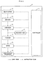
- Fig. 1 is a block diagram showing a configuration of a card embosser according to a first embodiment of the present invention and Fig. 2 is a flowchart showing the operation of the card embosser.
- This card embosser 1 includes: a multi-hopper block 12 having a mechanism for storing one or more than one kinds of cards to be issued and feeding cards one by one; an encoding block (encoder) 13 for carrying out a magnetic data read-in and write-in to a card fed from the multi-hopper block according to an instruction from a control block 11; an emboss block (embosser) for embossing an account number, a personal name, and the like on a card fed, and embossing an identification pattern for identifying a character or phrase indicating a recovery condition; a tipper block 15 for applying a color to the identification pattern embossed on the card; an eject/receive block (interface) 18 for ejecting a card out of the apparatus or feeding a card inserted into the apparatus, into the interior of the apparatus; a recovery box 17 for accumulating a card which has caused an error during an issuing or a card to be recovered because of term expiration; a control block 11 for
- the control block 11 controls operation of respective blocks so as to read an encoded information and an embossed information as well as a tipping error information.
- operations of the respective blocks constitute an information reader, which may have any configuration if a necessary information can be detected.
- the multi-hopper block 12 which has received the instruction sends out a card specified.
- the specified card is fed by the feeding means to the encoding block 13.
- a magnetic data supplied from the control block is written on the card.
- the card After the magnetic data is written in, the card is supplied to the emboss block 14, where a data (such as an account number and a personal name) supplied from the control block 11 is embossed on the card. After the embossing is complete, the card is sent to the tipper block 15, where a color is applied on a pattern embossed in the emboss block 14. After this coloring, the card is sent out of the apparatus through the eject/receive block. Thus, a normal card issuing is complete.
- a data such as an account number and a personal name
- a first factor is that an error is caused prior to embossing on the card in the emboss block 14 (step 101).
- the error may be an encoding disabled error.
- a second recovery factor is that an error has occurred after the embossing on the card in the emboss block 14 (step 103).
- the error may be a tipping error in the tipping block.
- a third recovery factor is that a card has been prepared normally and fed to the eject/receive block 16 but a wait state continues without removal of the card by a customer who has forgotten about the card (step 105).
- a fourth recovery factor is that a card whose term has expired is received and new card is to be issued (step 107).
- the control block 11 sends a recovery operation instruction to the respective blocks (step 109).
- the respective blocks receive the instruction and start the recovery operation.
- a card which has caused the recovery factor should be moved away from the site of the recovery factor to the emboss block 14.
- a feed instruction is issued (step 110) and it is checked whether card can be moved away from the recovery factor site (step 111). If it is decided that the card cannot be carried away from the site (an error such as card clogging), the apparatus down enters a down state (step 122) to wait for a processing by an operator (step 123). If the card can be carried away from the site, the recovery factor is identified (step 112).
- the card is directly carried to the recovery box 17 without being embossed according to a feed instruction (step 118).
- a feed instruction to the recovery box 17 is issued (step 118)
- a feed instruction to the emboss block 14 is issued (step 113) and a check is made to decide whether the card can be fed (step 114). If the feeding is impossible, the apparatus enters the down state (step 122) to waif for a processing by an operator (step 123). If the feeding is possible, the card is fed to the emboss block 14.
- a feed instruction to the recovery box 17 is issued so as to contain the card in the recovery box 17 (steps 118 to 123) as has been described above.
- the recovery factor can easily be identified from a card external view, cards can be grouped effectively without requiring a plurality of sections in the recovery box 17, which contributes to reduce the size of the entire apparatus.
- the character strings "ERROR CARD” and “VOID CARD” embossed on cards enable to visually identify incorrect cards, which in turn helps to prevent an unauthorized reuse of the cards.
- the aforementioned character strings are embossed on the magnetic stripe, it becomes impossible to read or write a magnetic data, which surely prevents an unauthorized reuse of the card.
- Fig. 3 is a block diagram showing a configuration of a card embosser according to the second embodiment and Fig. 4 is an operation flowchart of the card embosser.
- the card embosser 2 of Fig. 2 includes a multi-hopper block 12, an encoding block 13, an emboss block 14, a tipper block 15, an eject/receive block 16, a recovery box 17, a control block 11, and feed means (not depicted) for feeding a card to respective blocks.
- the card embosser according to the second embodiment includes a punch block 18 between the emboss block and the tipper block 15, for punching a hole in an error card or a card whose term has expired.
- the punch block (puncher) 18 is provided between the emboss block 14 and the tipper block 15, but it is also possible to provide the punch block 18 between the tipper block 15 and the eject/receive block 16, or immediately before the recovery box 17.
- a card recovery in the second embodiment is carried out as follows. There are four recovery factors.
- a first recovery factor is that an error has occurred prior to embossing on the card by the emboss block 14 (step 201). For example, an emboss disabled error is caused.
- a second recovery factor is that an error has occurred after embossing on the card (step 203). For example, the error is a tipping error.
- a third factor is that a card has been created normally and fed to the eject/receive block 16 but is not removed by a customer who has forgotten about the card (step 205).
- a fourth factor is that a card whose term has expired is received and a new card is to be issued (step 207).
- the control block issues an instruction for recovery operation to the respective blocks (step 209).
- Each of the blocks upon receiving the instruction, starts a necessary operation.
- the card which has caused a recovery factor should be fed from the site of the recovery factor to the punching block 18.
- a feed instruction is issued (step 210) and a check is made whether the card can be moved from the recovery factor site (step 211). If the card cannot be moved (card clogging error), the apparatus enters the down state (step 220) waiting for a processing by an operator )step 221). If the card can be moved, the recovery factor is identified (step 212).
- the card is fed to the recovery box 17 (steps 218, 219).
- an instruction to feed to the punching block 18 is issued (step 213) and it is checked whether the card can be moved (step 214). If the card cannot be moved, the apparatus enters the down state (step 220) to wait for a processing by an operator (step 221). If the card can be moved, the card is fed to the punching block 18, where the card is punched to form a hole (step 215).
- the recovery factor can be identified by visual observation, the recovered cards can be processed afterward with a high efficiency, and there is no need of providing a plurality of sections in the recovery box 17, which contributes to reduce the apparatus size.
- cards having punched holes can easily be distinguished as abnormal cards and this prevents an unauthorized reuse of the cards.
- the holes are punched on the magnetic stripe, it is impossible to read or write a magnetic data, which surely prevents an unauthorized reuse.
- the recovery factor can be identified by visual observation, there is no need of providing a plurality of sections in the recovery box for containing different recovery factors of the recovered cards. That is, a single recovery box is sufficient, which significantly reduces the entire apparatus size.
- a recovered card has an emboss or a punched hole
- the card can easily be recognized as a abnormal card, which prevents an unauthorized reuse of the card.
- an emboss or hole is formed on a magnetic stripe, it is impossible to read or write a magnetic data and accordingly, it is further sure to prevent an unauthorized reuse of the card.
Landscapes
- Physics & Mathematics (AREA)
- General Physics & Mathematics (AREA)
- Engineering & Computer Science (AREA)
- Theoretical Computer Science (AREA)
- Credit Cards Or The Like (AREA)
- Conveying Record Carriers (AREA)
- Control Of Vending Devices And Auxiliary Devices For Vending Devices (AREA)
Applications Claiming Priority (3)
| Application Number | Priority Date | Filing Date | Title |
|---|---|---|---|
| JP9188285A JP2904195B2 (ja) | 1997-07-14 | 1997-07-14 | カードのリジェクト/回収方法、及びカードエンボッサ |
| JP18828597 | 1997-07-14 | ||
| JP188285/97 | 1997-07-14 |
Publications (2)
| Publication Number | Publication Date |
|---|---|
| EP0892361A2 true EP0892361A2 (de) | 1999-01-20 |
| EP0892361A3 EP0892361A3 (de) | 2001-02-28 |
Family
ID=16220970
Family Applications (1)
| Application Number | Title | Priority Date | Filing Date |
|---|---|---|---|
| EP98113103A Withdrawn EP0892361A3 (de) | 1997-07-14 | 1998-07-14 | Kartenrückgewinnungsverfahren und Kartenausgabevorrichtung |
Country Status (3)
| Country | Link |
|---|---|
| US (1) | US6039412A (de) |
| EP (1) | EP0892361A3 (de) |
| JP (1) | JP2904195B2 (de) |
Families Citing this family (6)
| Publication number | Priority date | Publication date | Assignee | Title |
|---|---|---|---|---|
| US6394346B1 (en) * | 1999-10-07 | 2002-05-28 | Cubic Corporation | Contactless smart card high production encoding machine |
| CA2476466C (en) | 2002-02-15 | 2009-04-21 | Coinstar, Inc. | Apparatuses and methods for dispensing cards |
| US9233812B2 (en) * | 2005-12-05 | 2016-01-12 | Outerwall Inc. | Card dispensing apparatuses and associated methods of operation |
| CN100485715C (zh) * | 2006-01-10 | 2009-05-06 | 沈阳友联电子装备有限公司 | 智能ic卡个人化数据写入时在线补卡方法及实现装置 |
| JP4049199B1 (ja) * | 2006-10-30 | 2008-02-20 | 富士ゼロックス株式会社 | 情報処理装置、情報処理方法及びプログラム |
| JP6048076B2 (ja) * | 2012-11-05 | 2016-12-21 | 凸版印刷株式会社 | 携帯可能な記憶媒体の発行処理装置 |
Family Cites Families (7)
| Publication number | Priority date | Publication date | Assignee | Title |
|---|---|---|---|---|
| JPS631836A (ja) * | 1986-06-18 | 1988-01-06 | Toshiba Corp | 竪形回転体装置 |
| US4827425A (en) * | 1986-10-31 | 1989-05-02 | Thorn Emi Malco, Incorporated | System for personalization of integrated circuit microchip cards |
| JPH0536568A (ja) * | 1991-07-29 | 1993-02-12 | Mitsubishi Materials Corp | 積層セラミツク電子部品の製造方法 |
| US5266781A (en) * | 1991-08-15 | 1993-11-30 | Datacard Corporation | Modular card processing system |
| US5771245A (en) * | 1992-03-20 | 1998-06-23 | Xerox Corporation | Process for independently protecting two dimensional codes from one or more burst errors patterns |
| US5433364A (en) * | 1993-02-19 | 1995-07-18 | Dynetics Engineering Corporation | Card package production system with burster and carrier verification apparatus |
| US5442162A (en) * | 1994-04-05 | 1995-08-15 | The Foundation For Physical Sciences | Traveler's check and dispensing system therefor |
-
1997
- 1997-07-14 JP JP9188285A patent/JP2904195B2/ja not_active Expired - Fee Related
-
1998
- 1998-07-14 US US09/114,899 patent/US6039412A/en not_active Expired - Fee Related
- 1998-07-14 EP EP98113103A patent/EP0892361A3/de not_active Withdrawn
Also Published As
| Publication number | Publication date |
|---|---|
| US6039412A (en) | 2000-03-21 |
| JP2904195B2 (ja) | 1999-06-14 |
| EP0892361A3 (de) | 2001-02-28 |
| JPH1131198A (ja) | 1999-02-02 |
Similar Documents
| Publication | Publication Date | Title |
|---|---|---|
| KR910000619B1 (ko) | 휴대할 수 있는 기억매체의 처리장치 | |
| JP2950190B2 (ja) | カード発行装置 | |
| EP0134110A2 (de) | Lese- und Schreibvorrichtung für Identifizierungskarten | |
| JP3755067B2 (ja) | カードのバッチ式カスタム化方法 | |
| US6039412A (en) | Card recovery method and card issuing apparatus | |
| EP0426093A2 (de) | Kartenähnlicher Aufzeichnungsträger und Verfahren zur Verhinderung von Missbräuchen | |
| EP0311417B1 (de) | Verarbeitungsvorrichtung für ein tragbares Speichermedium | |
| HK1001478B (en) | Processing apparatus for a portable storage medium | |
| US5173850A (en) | Apparatus and method for checking print quality of turnaround medium | |
| JPS62262266A (ja) | カ−ド処理装置及びカ−ド | |
| JP2740291B2 (ja) | 証券処理装置 | |
| JPH0830815A (ja) | 無線カードの再利用システム | |
| JP3481640B2 (ja) | リーダーライタ装置及びプリペイドカードシステム | |
| JP2003216984A (ja) | ロール紙の発券端末装置および管理システム | |
| JPS63311495A (ja) | 投票システムの発券管理方式 | |
| JPH09311955A (ja) | 券片発行方法 | |
| JPH10207999A (ja) | 2次元データシンボル処理システム | |
| JP2836632B2 (ja) | Idカードの発行方法 | |
| JPS63231592A (ja) | カ−ドによる管理情報処理方法 | |
| JPH08221606A (ja) | 券片発行方法およびその装置ならびにこれに用いる券片 | |
| JPH04294482A (ja) | 手動式磁気カード読取装置 | |
| JPH10188090A (ja) | カード発券機 | |
| JPH07104981B2 (ja) | 機器の使用状況管理方法 | |
| JPH0410089A (ja) | Idコード識別方法 | |
| JPH1196324A (ja) | カードの不正変造防止方法および装置並びにカード |
Legal Events
| Date | Code | Title | Description |
|---|---|---|---|
| PUAI | Public reference made under article 153(3) epc to a published international application that has entered the european phase |
Free format text: ORIGINAL CODE: 0009012 |
|
| AK | Designated contracting states |
Kind code of ref document: A2 Designated state(s): DE GB IT |
|
| AX | Request for extension of the european patent |
Free format text: AL;LT;LV;MK;RO;SI |
|
| PUAL | Search report despatched |
Free format text: ORIGINAL CODE: 0009013 |
|
| AK | Designated contracting states |
Kind code of ref document: A3 Designated state(s): AT BE CH CY DE DK ES FI FR GB GR IE IT LI LU MC NL PT SE |
|
| AX | Request for extension of the european patent |
Free format text: AL;LT;LV;MK;RO;SI |
|
| 17P | Request for examination filed |
Effective date: 20010511 |
|
| AKX | Designation fees paid |
Free format text: DE GB IT |
|
| GRAP | Despatch of communication of intention to grant a patent |
Free format text: ORIGINAL CODE: EPIDOSNIGR1 |
|
| GRAS | Grant fee paid |
Free format text: ORIGINAL CODE: EPIDOSNIGR3 |
|
| STAA | Information on the status of an ep patent application or granted ep patent |
Free format text: STATUS: THE APPLICATION IS DEEMED TO BE WITHDRAWN |
|
| 18D | Application deemed to be withdrawn |
Effective date: 20110131 |