EP0892586A2 - Hochtemperaturmikrowellenofen zum Schmelzen, Zersetzen oder zu Asche verbrennen - Google Patents
Hochtemperaturmikrowellenofen zum Schmelzen, Zersetzen oder zu Asche verbrennen Download PDFInfo
- Publication number
- EP0892586A2 EP0892586A2 EP97308663A EP97308663A EP0892586A2 EP 0892586 A2 EP0892586 A2 EP 0892586A2 EP 97308663 A EP97308663 A EP 97308663A EP 97308663 A EP97308663 A EP 97308663A EP 0892586 A2 EP0892586 A2 EP 0892586A2
- Authority
- EP
- European Patent Office
- Prior art keywords
- insulating structure
- microwave
- chamber
- cavity
- temperature
- Prior art date
- Legal status (The legal status is an assumption and is not a legal conclusion. Google has not performed a legal analysis and makes no representation as to the accuracy of the status listed.)
- Withdrawn
Links
Images


Classifications
-
- H—ELECTRICITY
- H05—ELECTRIC TECHNIQUES NOT OTHERWISE PROVIDED FOR
- H05B—ELECTRIC HEATING; ELECTRIC LIGHT SOURCES NOT OTHERWISE PROVIDED FOR; CIRCUIT ARRANGEMENTS FOR ELECTRIC LIGHT SOURCES, IN GENERAL
- H05B6/00—Heating by electric, magnetic or electromagnetic fields
- H05B6/64—Heating using microwaves
- H05B6/647—Aspects related to microwave heating combined with other heating techniques
- H05B6/6491—Aspects related to microwave heating combined with other heating techniques combined with the use of susceptors
- H05B6/6494—Aspects related to microwave heating combined with other heating techniques combined with the use of susceptors for cooking
Definitions
- This invention relates to apparatuses, components of such apparatuses and analytical processes, where microwave irradiation is used directly or indirectly to heat samples at temperatures higher than 1000 °C, up to achieve the sample melting, decomposition or reduction to ash.
- the field of the invention is related to microwave furnaces where the microwaves are generated by a source, like a magnetron, and are coupled to and contained in a chamber with conductive walls.
- Such chamber having a thermal insulating structure inside it, transmissive of microwave radiation, used to retain the heat generated by a microwave absorbing material of high melting point placed inside the insulating structure.
- a thermal insulating structure inside it, transmissive of microwave radiation, used to retain the heat generated by a microwave absorbing material of high melting point placed inside the insulating structure.
- this invention is related to an apparatus for high temperature thermal treatment of samples which gives the possibility to have a direct look at the samples while the microwaves are on and the samples are under thermal treatment, in this way the operator can achieve in a faster time the definition of the process procedure, without loosing desirable properties such as a quick temperature rising time or the thermal insulation, which also saves energy.
- the invention is related to components of said apparatus which gives the possibility to use, in an easy way, different configurations of the thermal insulating structure to fit better the user's needs.
- Another important aspect of this invention is related to the improvement of uniformity of the microwave field inside the cavity, and consequently to the improvement of the uniformity of the sample heating. A more uniform microwave field inside the cavity is achieved through the design of the of the apparatus walls.
- Microwaves have been used to sinter, melt, decompose or reduce to ash several materials. This is achieved either by direct absorption of the material of interest or by heating a material with high melting temperature which absorbs microwaves and then radiates to the material of interest, if this last one does not absorb microwaves.
- the sintering of, for example, ceramics by microwave power is the subject of several review articles and books [Ann. Chim. (Paris) 1996, 21]. Melting by microwaves is used in metallurgy and to density waste, especially if radioactive [Crit. Rev. Anal. Chem. 25, 43-76(1995), Material Research Society Symposium Proceedings volume 347]. Pyrolytic decomposition is well established as well as ash determination.
- the possibility of having a direct look at the sample while the microwaves are on implies that the sample shall be illuminated.
- the art known illuminates the microwave chamber by wired lamps situated outside the chamber and shielded from the microwaves by a grill or by wireless lamps, powered by microwave, [See Proc. SPIE-Int. Soc. Opt. Eng., 1994, p.2282 and JP 03 25,854] but, to the knowledge of the assignees, these lamps are used only at room temperature and have not been used inside the thermal insulating structure of a furnace.
- the present invention will then allow to have a direct look at the sample under heat treatment without altering the thermal insulation and while the microwaves are on.
- the microwave furnace object of the present invention comprises a microwave radiation generating device coupled through a waveguide and one or more apertures to a microwave containing chamber.
- the chamber is a parallelepiped with a door. All the chamber walls are made of a metallic material which reflects microwaves and have low electrical resistivity. Some or all the conducting walls have a rough surface, preferably covered by planar sheets of a microwave transparent material.
- the chamber has a door made of a metal or a metal alloy with a viewing window with glass or quartz sheets in both sides with in between a metal grill, to contain the microwaves within the chamber.
- the bottom of the door has a grate to allow the entrance of air from the exterior to cool the surface of the quartz or glass that faces the interior of the chamber.
- the metal part of the interior of the door has one or more regions with metal grills which allow the entrance of the air in the chamber while shielding the microwaves.
- the bottom of the chamber and the walls have slabs or screws used to fix the thermal insulating structure in the chamber and also to improve the tuning of the chamber with the waveguide, to reduce the reflected wave.
- the bottom of the chamber has a hole where a ceramic bar can be fixed to a motor situated under the chamber.
- One of the chamber walls has also a passageway with a metallic grill covering it to allow the cooling air to pass towards an external fan which has the possibility to vary its velocity. This exhaust fan provides the ventilation to the whole chamber and is controlled by an external electronic control unit.
- On the chamber walls there are also inlets and outlets openings for quartz pipes used for the passage of gas in and out of the chamber towards or from the interior part of the thermal insulating structure.
- the front part of the apparatus has a numeric display where the temperature of the zone where the sample is undergoing thermal treatment can be read and also there are signal lights to show the status of the apparatus.
- the temperature is measured by a thermocouple, or other temperature sensing means, situated inside the chamber where the sample is.
- the apparatus is controlled by a microprocessor situated in an external control unit with a high resolution dot-matrix display and a keypad and by another microprocessor situated in the body of the apparatus.
- the thermal insulating structure is composed of three matching parts.
- the bottom part of the thermal insulating structure has a hole in its body to let pass through the ceramic bar connected to the external motor.
- the top part of the thermal insulating structure has one or more holes where a thermal sensing means, like a thermocouple, and quartz pipes can be inserted.
- the thermocouple measures the temperature inside the sample cavity and the quartz pipes allow gas exchange or gas removal from the sample cavity.
- the front part of the thermal insulating structure has three versions, which can be exchanged according to the needs of the user.
- the first version has the form necessary to complete the external parallelepiped of the thermal insulating structure, leaving also an empty internal parallelepiped, the sample cavity, where the samples are placed.
- This version of the front part has on the external face a ridge which functions as a handle or grip for easy hand removal, closure or adjustment of the part itself.
- the second version of the front part of the insulating structure has the same form but with a viewing window made by making a conical or trapezoidal hole in a structure similar to the previously described one and then closing both surface holes with quartz windows. On the walls of the sample cavity a small groove is made where a microwave powered electroless lamp can be placed. This lamp is made with a quartz tube which was closed under vacuum with inside a phosphorous, like ZnS, and traces of mercury, indium or tin.
- the third version of the front part of the insulating structure is made of three sections.
- the rotating part is made by taking a ceramic platform and connecting it to the rotating axis that passes through the base of the insulating structure.
- the ceramic platform is almost tangent to the interior side walls of the sample cavity.
- the platform has a slot for the insertion of a heating element and also two protuberances that match corresponding holes of the central section of the front part of the insulating structure. When the platform rotates this section rotates too, moving towards the interior of the insulating structure and showing the samples placed on the platform.
- the heating element attached to the platform keeps heating the samples while the platform is rotated towards the viewer.
- the heating elements made of a composite of high temperature ceramic cement and silicon carbide powder are placed close by or attached to the walls of the sample cavity.
- the relative proportions of SiC and cement, the SiC grain size, the thickness and the shape are chosen so to maximise the microwave absorption and the uniformity of the heating.
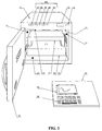
- FIG 1 a perspective view of the microwave furnace ( 11 ). It has a power button ( 12 ) to turn on/off the apparatus.
- the microwave retaining chamber which is a parallelepiped defined by a bottom ( 13 ), a top ( 14 ), one left hand side ( 15 ), one right hand side ( 16 ) and a rear ( 17 ) walls and a door ( 18 ), shown open.
- the dimensions of the microwave chamber are large enough to contain the thermal insulating structure. In the preferred configuration a clearance of 1,5 cm is left between the chamber walls and the thermal insulating structure walls, but other clearance lengths can be left.
- the external control unit ( 22 ) receives the information on the temperature inside the chamber from a thermocouple, not seen in figure 1, and sends the necessary electronic signals back to the switching system of the electrical power to control the average microwave power conveyed towards the microwave chamber.
- a numeric display ( 23 ) with the readout of the temperature inside the sample cavity and signal lights ( 24 ) that will be described later.
- the speed of the fan can be adjusted to the user's needs through the external control unit ( 22 ).
- the microwaves are generated by a magnetron, which has a cooling fan and the necessary electrical circuits and electronic components needed to be powered.
- the magnetron antenna emits microwaves at a frequency normally of 2450 MHz. Also other frequencies are possible, preferably in the range of 850 to 25000 MHz.
- behind the rear wall ( 17 ) there is a rectangular waveguide formed in part by the rear of the chamber wall itself.
- the magnetron antenna radiates in the waveguide, coupled to the chamber through one or more rectangular apertures ( 26 ).
- the magnetron radiates at the centre of the rectangular symmetric waveguide. At both ends of the waveguide the microwave is directed towards the chamber by a 45° plane, this angle is measured with respect to the wide face of the waveguide; the plane ends in the rectangular aperture ( 26 ).
- Other coupling configurations are also possible, the previously described one is not a limitation to the present apparatus.
- the average microwave power range can be varied in steps of 1% up to full power, which can be from 0,3 to 1,8 kW. Other ranges of power can be used but a magnetron with radiating power of 1,45 kw usually allows to reach temperatures of 1000 °C inside the sample cavity in less than 1 hour and temperatures of 700 °C in less than 20 minutes.
- the electrical circuits and components which give the electrical power to the magnetron are known in the art and thus not described here.
- the chamber walls are made of a conducting material a metal or metal alloy, for example aluminum or stainless steel.
- the chamber top wall and a side wall are composed by two laminates.
- the exterior laminate ( 27 ) seen in the figure removed from the left hand side wall ( 15 ), is a flat panel made of a microwave transparent material, for example a plastic like polytetrafluoroethylene.
- the interior laminate ( 28 ) is made of metal or other microwave reflecting material with low electrical resistivity, in the preferred configuration a sheet of stainless steel. Such laminate is wrapped to give a rough surface with valleys and hills that deviate from the ideal flat surface by no more than one tenth of the microwave wavelength, in the preferred case around 1 centimetre.
- a second embodiment of this wall can be made with a composite structure, using methods known in the art of composites, where the previously described laminated or a net made by a stainless steel wire, with small mesh, to avoid microwave leaks, is embedded with a fused plastic, sufficiently transparent to microwaves and with yield temperature higher than 130 °C, or with a fluid ceramic cement in a preform to give a composite with flat surface but with the internal, metallic part having still a rough surface.
- This composite is then screwed firmly or welded to the chamber metallic structure using the metallic parts of the composite that on purpose were not covered by the plastic or ceramic matrix.
- One of the discoveries of the present invention is that if the metallic wall surface is rough the field inside the chamber is more uniform than for metallic walls with flat surface and that if the difference between hills and valleys of the rough surface is about one fifth of the radiation wavelength or lower, the microwave power transferred to the microwave absorbers inside the chamber is not lowered when the conductive walls are rough, compared to the power absorbed when the chamber conductive walls are flat.
- An advantage of the previously described composite walls is that the metallic part of the wall can be thinner than a wall made of only metal because the structural and mechanical needs of the apparatus walls are satisfied by the rest of the composite. In the case of a composite made with a plastic laminate or matrix there is a decrease of the total apparatus weight when the composite walls are used.
- the bottom of the chamber and the walls have slabs ( 29 ) or screws ( 30 ) used to fix or restrain the movement of the thermal insulating structure in the chamber.
- the length of the screws and the length and orientation of the slabs can be adjusted to improve the tuning of the chamber with the waveguide, to reduce the reflected wave.
- the bottom of the chamber has a hole ( 31 ) where a ceramic bar ( 32 ) can be fixed to a motor, not seen in the figure, situated under the chamber. This bar is the axis where the rotating platform of the thermal insulating structure is attached.
- On the chamber walls there are also inlets and outlets openings ( 33 ) where quartz pipes can be fixed for the passage of gas in and out of the chamber towards or from the interior part of the thermal insulating structure.
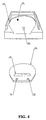
- the chamber has a door, figure 3, with a viewing window ( 34 ) with a quartz or a glass slab facing the interior wall of the chamber ( 35 ) and a glass or a plastic sheet made of a transparent polymer like polycarbonate, covering the exterior side ( 36 ), with in between a metal or a metal alloy grill ( 37 ) which acts as a shield to contain the microwaves inside the chamber.
- the bottom of the door has a grate ( 38 ) which allows the entrance of air from the exterior to cool the door. The circulation of the air is forced to a path to give preferential cooling to the region where the window is. For this reason two slabs, of which only one is seen, ( 39 ) are inserted inside the door to form a duct.
- thermal insulating structure made of a material transparent to microwaves (higher than 98% transmission), with thermal conductivity at 1000 °C below 0,22 W/mK, modulus of rupture in the range of 320-1100 kPa, of low density (between 0,2-0,5 g/c. cm.), thermally stable at temperatures at least up to 1250 °C and chemically resistant to the atmosphere present in the sample cavity at the operating temperatures.
- Panels of pressed quartz or ceramic fibres or foams can be used, like panels of the pressed ceramic fibre KAOWOOL, available from Morgan-Morganite Ceramics Fibres Limited (Bromborough, UK), preferably of quality Strong Board, for general uses, or quality Zirconium, if during the sample treatment there is the presence of an atmosphere made of gases with base properties.
- the panels should be heat resistant and stable at temperatures up to 1100 °C for times up to few hours and their properties should no deteriorate appreciably with the use at such temperatures. If temperatures higher than 1100 °C are to be undertaken the appropriate panels should be used.
- the thickness of the panels should be enough to allow a temperature difference of more than 1050 °C between the external surface of the insulting structure and the internal one, where the samples are located.
- the thermal insulating structure is composed by three combinable, separable and matching parts.
- the parts of the thermal insulating structure are made by cutting, grinding and machining the panels to the desired shapes, shown in figures 4-9 and described below.
- the panels can be cemented to themselves but is preferable to use thick enough panels to avoid cementing, because cementing may alter, after some time, the efficient functioning of the structure.
- the bottom part of the thermal insulating structure is shown in figure 4, it is shaped to form an internal cavity which together with the top part of the insulating structure forms the sample cavity. It has slots close to the internal wall where the microwave heating element can be placed and a circular shaped groove with a hole at the centre ( 41 ) to let pass through the ceramic bar, coming out from the bottom of the chamber.
- the ceramic bar ( 32 , figure 2) is made with a temperature resistant ceramic almost transparent to microwaves, like a low defect alumina.
- the platform is made with a thermal resistant ceramic, it can be connected to the ceramic bar so it can be rotated by the external motor.
- the platform ( 42 ), shown removed in figure 4, can be used with the third version of the front part of the insulating structure when the sample has to be seen directly even when the temperature is rising and the microwaves are on.
- the floor of the bottom part of the thermal insulating structure has a circular groove ( 43 ) to allow the rotation of the third version of the front part of the thermal insulating structure.
- the holes for the quartz pipes can also be located on one side and one or more small holes can be done in the chamber side wall ( 33 , figure 2), also connected to the same quartz pipes, to allow gas exchange with the exterior of the apparatus.
- a groove is made in the upper part of one of the surfaces of the top insulating structure, there a microwave powered electroless lamp ( 46 ) can be placed inside the sample cavity walls.
- the front part of the thermal insulating structure has the function of closing the sample cavity and can thus be considered the door of the sample cavity. It can be put in place or removed by the operator as in first and second versions below, or movable as in the third version. All three versions match and complement the bottom and top part of the insulating structure and can be therefore exchanged with one another according to the needs of the user.
- This is another advantage of the present invention because extends the efficient use of the apparatus to several processes optimizing in a simple way the apparatus configuration according to the particular goal of the user.
- the sample cavity has in the preferred configuration, a height of 14 cm, is 26 cm wide and 16 cm deep. Other dimensions are possible if compatible with the thermal insulating structure and, ultimately, the microwave chamber size. In particular larger sizes can be reached with thinner thermal insulating walls or larger microwave chamber sizes. In this last case, an increase of the magnetron power is also convenient.
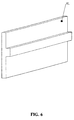
- the first version of the front part of the thermal insulating structure shown in figure 6, has the form necessary to complete the external parallelepiped of the thermal insulating structure leaving an empty internal parallelepiped, the sample cavity, where the samples are placed.
- This part has on the external face a ridge which functions as a handle or grip for easy hand removal, closure or adjustment of the part itself ( 47 ).
- This first version is used preferentially when the thermal procedure to be applied to the samples is well known and a fast temperature rising time is important.
- next two versions of the front part of the thermal insulating structure are used preferentially when is important to look at the samples while the thermal treatment is going on with or without microwaves on. This is useful when a new thermal procedure is being studied or when the particular set of samples require special attention even with a known procedure.
- the second version of the front part of the insulating structure, figure 7, has the same form of the first one but with a viewing window, made by making a conical or trapezoidal hole in a structure similar to the previously described one and then closing both surface holes with quartz windows ( 48 ).
- the external window is rectangular and has dimensions of 5 cm x 8 cm
- the internal one is also rectangular with dimensions 5 cm x 14 cm.
- the microwave powered lamp is off when the microwaves are off, as seen in figure 5, there is also a small window ( 49 ), using quartz sheets, on the right hand side of the top part, in correspondence with the lamp situated in the right hand side wall of the insulating chamber.
- This second version is particularly useful when the samples must be seen during the thermal treatment and the atmosphere of the sample cavity must be controlled or when it is important to have low thermal losses but, at the same time, there is the need to have a look at the samples during most part of the duration of the thermal treatment.
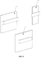
- the third version of the front part of the insulating structure is made of three sections, figure 8, that match between themselves and are complementary for the formation of a form similar to the ones described in the previous versions of the front part.
- Two of the sections are identical ( 50 ) with a shape that fits the sides of the top and bottom structures, leaving a central space that is filled by the third section ( 51 ).
- This last is the central part, shown in figure 9, which is fixed on the rotating platform ( 42 ), shown in fig. 4, with the aid of the two protuberances of the platform ( 52 ) or with the aid of the slot ( 53 ) that fixes part of the heating unit to the disk.
- the central part can rotate so to close the insulating structure when the samples are rotated towards the interior of the sample cavity and thus cannot be seen from the microwave chamber door.
- the sample can be seen by the operator when this central part rotates 180°.
- the rotating part is made by taking a ceramic platform and connecting it to the rotating axis that passes through the base of the insulating structure, using a complementary geometry made on purpose in the ceramic bar and in the bottom part of the platform.
- the form of the platform is a disk with a cut through a cord.
- the ceramic platform is as close as possible to the rear wall of the sample cavity and almost tangent to the side walls.
- thermocouple enters the chamber preferably through the rear of the top part of the insulating structure to give more stability but it can also enter through a hole situated on the ceiling or elsewhere as far as the thermocouple does not interfere with the rotating part movement.
- the holes for gas exchange or gas replacement can be placed on the sides of the insulating structure or elsewhere because they do not need to enter the sample cavity and consequently do not interfere with the rotation.
- the inlet shall be put through a hole situated on the ceiling of the top part of the insulating structure because even this would give a gas flux over the sample even when the sample is rotated towards the microwave chamber door or shall be put on the left hand side as close as possible to the internal part of the cavity door.
- This third configuration is preferentially used when the samples must be seen for short periods of time and the thermal insulation shall be high at other times; it can be used when the sample has to be seen and the second version cannot be used because the samples produces too much smoke or when there is the need to evacuate in a fast way the smoke produced.
- This configuration also allows a fast cooling down of the sample without the direct handling of the sample or the insulating structure door by the operator; this is achieved by just leaving the door of the microwave chamber open or closed, the microwaves off and the samples rotated towards the microwave chamber's door and the exhaust fan at maximum speed.
- the heating elements made of a composite of high temperature ceramic cement and silicon carbide powder are placed close by or attached to the walls of the sample cavity, grooves or slots can be made for the purpose.
- the composition, the SiC grain size, the thickness and the shape of the heating elements are chosen so to maximise the microwave absorption and the uniformity of heating.
- thermocouples used inside the microwave chamber must be covered by a metallic sheath, usually stainless steel, electrically grounded to the microwave chamber conducting walls or, equivalently, to the metallic structure of the chamber which coincides with the apparatus electric ground.
- a metallic sheath usually stainless steel
- the thermocouples which go inside the sample cavity and the sheath that covers them must withstand the maximum furnace temperatures and the sheath must remain unaffected by any combustion products or gases that are introduced in the sample cavity.
- the electroless lamp is made with a quartz tube whose interior surface is covered by a layer of a phosphorous, like ZnS powder, and traces of mercury (or a decomposable mercury salt), indium or tin are placed inside the tube.
- the tube is then closed under vacuum.
- the traces of mercury, tin or indium and the vacuum realized during the closure are calculated to get a total pressure inside the closed lamp between 10 - 150 mm Hg and a partial pressure of the metal included, when the metal evaporates due to the presence of microwaves, between 2-100 mm Hg.
- the lamp is preferentially used with the second version of the front part when the external illumination is not enough for the conditions of the sample and of the thermal treatment under consideration.
- the apparatus is controlled by a microprocessor situated in an external control unit with a high resolution dot-matrix display, ( 55 ) of figure 1, and a keypad, ( 56 ) of figure 1, and by another microprocessor situated in the body of the apparatus, outside the microwave chamber.
- the external control unit is the main interface with the operator and sends the main operation instructions to the apparatus via an infrared communication system. Through the keypad the operator can enter the conditions of the thermal treatment and other data which are then stored in a temporary RAM memory or, if so desired, can be stored permanently for further use.
- the control unit When all the information has been received the control unit enables the start procedure according to the conditions of the programmed thermal treatment and sends a signal to the microprocessor situacted inside the apparatus which in turn acts on a solid state relay that turns on the microwave power by closing the contact of the primary side of the high voltage transformer.
- the voltage signal from the thermocouple is converted by an A/D converter and is read by the microprocessor situated in the body of the apparatus.
- This information is sent to the external control unit and to the temperature display ( 23 , figure 1) situated on the front part of the apparatus.
- the external control unit compares the reading with the difference to the set temperature, following a pre-programmed differential control system procedure, known in the art, to avoid temperature overshoots. and sends back this information to the internal microprocessor which then acts on the solid state switch.
- the operator can also program the speed of the chamber exhaust fan because the external control unit can act on the power supply of the fan varying the voltage applied to it. In this way if the sample in the furnace produces smoke the fan speed can be increased whereas if the sample does not produce smoke the speed can be reduced to a minimum to increase the rate of temperature rise.
- the fan speed can be programmed to be low at low sample cavity temperatures and higher at higher temperatures, for this purpose is used a second thermocouple, covered by a metallic sheath electrically grounded to the chamber wall. The tip of the sheath is positioned in contact with the exterior surface of the top part of the thermal insulating structure by inserting it one millimetre inside the insulating structure. The temperature is read by the microprocessor and then the fan speed can be modified from zero up to the maximum according to the thermal insulating structure surface temperature. The top part external surface is chosen because is the surface that reaches the highest temperature with the exhaust fan off.
- the microprocessor of the external control unit drives the dot matrix display of the control unit allowing the operator to see the time evolution of the temperature inside the sample cavity.
- the control unit can also drive a printer and has a serial port to allow a connection with another I/O device, usually a balance.
- the internal microprocessor sends the signals to the signal lights and to the temperature display, both situated in the front part of the apparatus.
- the exhaust fan has a Hall effect sensor that sends a signal to the microprocessor, if the fan turns; the microprocessor then acts on the solid state switch of the corresponding light, ( 57 ) of figure 1.
- the door has safety switches that do not allow the magnetron to emit microwaves with the door open, it also turns on the signal light that signals the door open ( 58 ).
- the magnetron is protected by a thermoswitch against overheating, turning it off. In case of such event a corresponding light will turn on ( 59 ).
- a light controlled by the microprocessor of the external control unit is turned on ( 60 ).
- This apparatus has several significant advantages over existing art apparatuses for high temperature treatment of samples and materials. Since the microwave field inside the chamber is more uniform the heating inside the sample cavity is better distributed and thus the samples respond all to the thermal treatment in similar manner and at the same time, in this way a plurality of samples can be treated using all the space available. The uniformity of the microwave field inside the chamber is especially important when the sample under treatment absorbs microwaves.
- each set of samples requires a study of the best conditions for the thermal treatment, especially in proximity of a phase transition from liquid to gas, when bubbles can make the samples spill over their container, then having a direct look at the sample during thermal treatment is an obvious advantage.
- There is a configuration of the insulating structure with a viewing window which is optimized for the viewing of the sample at all times without loosing the advantages of having a thermal insulation and of having the control over the atmosphere that the sample is in contact with.
- the apparatus can be easily modified-to adopt the configuration most suited for the needs of the user.
- Another configuration allows part of the structure to be rotated, in this way the sample can be directly seen for the amount of time desired without disrupting in a significant way the thermal treatment, and then, rotating back to the original position, the complete thermal insulation is recovered.
- This configuration can be used when samples produce large amounts of smoke or when it is desired to get e fast cooling time after the thermal treatment is done without a direct contact of the sample with the operator; the air flow of the exhaust fan can be regulated accordingly.
- the possibility to have a look at the samples is enhanced with the microwave powered lamp positioned inside the sample cavity.
- the door of the apparatus is air cooled from the interior. In this way it is considerably reduced the effect on the apparatus viewing window of the heat radiated from the sample cavity in all configurations of the insulating structure.
- thermocouple that measures the temperature at the surface of the insulating structure. This is particularly useful if to get a larger sample cavity is used a configuration of the insulating structure which is much thinner compared to the preferred one, if such a choice is made the surface temperature can be high.
- the measurement of the temperature by the microprocessor will automatically turn on the signal light on the front panel.
- the apparatus is modified by using two flat stainless steel laminates instead of the rough top and left hand side rough walls.
- cylindrical containers of diameter equal to 2.5 cm and height 5 cm. are placed with 20 cm 3 of water inside.
- the heating elements are withdrawn and the microwaves are turned on at average power of 900 watt. After 1 minutes the microwaves are turned off and the temperature on each container is measured. The results are shown in table 1.
- the flat laminates are replaced by laminates with rough metallic surfaces, as described in the preferred configuration above and the experiment is repeated, the results are shown in table 1.
- the microwaves were on at 900 kW until the empty sample cavity reached 1020 °C. Then the microwaves were turned off and the temperature of the cavity was measured as a function of time. In one case with the first version of the front part of the insulating structure, in another case with the second version of the insulating structure. The results are reported in table 2. The first version of the front part gives better insulation. This is especially relevant at the very high temperatures but as temperature lowers the two versions are almost equivalent.
- the apparatus was set in the preferred configuration with all the holes on the walls of the thermal insulating structure, but the one for the thermocouple, closed.
- a sample of polyethylene, weighting 2 g was put in a quartz container.
- the container was introduced in the sample cavity and the cavity was closed with the second version of the front part of the insulting structure (with a viewing window).
- a program was set in the external control unit to reach 800 °C at average power of 650 W. After the apparatus door was closed the microwaves were turned on by the control unit and the temperature started to rise. When the temperature was about 220 °C it was seen that smoke was coming out from the samples, to avoid that the smoke would carry out some sample the program in the external control unit was put in hold and the power was lowered to 500 W.
- the container was withdrawn from the furnace and weighted. The remaining weight was 0,02 g.
- the same experiment was repeated with the first version of the front part. The only difference in the procedure was that when the smoke was detected, when the sample cavity was around 250 °C, the microwaves were turned off and the apparatus was opened to have a look at the samples. As soon as the front part was removed the sample ignited and flames appeared inside the chamber. This constrained to stop the experiment. Of course, once the procedure is tested the front door needs not to be opened but to set up the procedure it is extremely convenient to have a viewing window.
- the experiment was repeated with the third version of the front part (the rotating front part). In this case when the smoke was seen the platform was rotated through the external control unit the smoke came out and the sample burned with flame. In this the operator was never close to the point where the flame was because the apparatus door was closed.
- the apparatus was set in the preferred configuration with all the holes on the walls of the thermal insulating structure, but the one for the thermocouple, closed.
- a sample of a nylon composite, weighting 2 g was put in a quartz container.
- the container was introduced in the sample cavity and the cavity was closed with the second version of the front part of the insulting structure (with a viewing window) a preset-program was used because the conditions were determined using a procedure similar to the one described in the previous example.
- the quartz crucible was withdrawn and the sample residue weight was 0.3 g, or 15% of the sample weight.
- a thermogravimetry analysis was also made following the same conditions, at the end the sample weight was 15.3% of the original. The agreement is quite good.
- the apparatus was set in the preferred configuration with all the holes on the walls of the thermal insulating structure, but the one for the thermocouple, closed.
- Tannic ether weighting 1 g was put in a quartz container.
- the container was introduced in the sample cavity and the cavity was closed with the second version of the front part of the insulting structure (with a viewing window).
- the average power was set at 650 W and the final temperature at 800 °C. It was seen from that when the sample cavity temperature was 500 °C the sample started to bubble, the microwave power was lowered, without spilling.
- the external control unit was programmed again to stay for 20 minutes at 480 °C and afterwards to reach 800 °C. No bubbling was seen afterwards.
- the quartz crucible was withdrawn and the sample residue weight was 0.01 g. Having the possibility to look at the sample avoided spilling and, consequently false results. Given the conditions of the experiment without a direct view to the sample the spilled material or its residues would not have been seen and the false results would not have been detected.
- the apparatus was set in the preferred configuration. NaHCO 3 , weighting 10 g was put in a quartz container. The container was introduced in the sample cavity and the cavity was closed with the third version of the front part of the insulting structure (with a rotating platform). The average power was set at 650 W and the final temperature at 400 °C. Every 10 minutes the platform was rotated to see the physical state of the sample. After about 30 min it was seen that the sample melted and was then left in the crucible for other 30 minutes. The crucible was then withdrawn and weighted. The resulting sample weight was 4.78 g.
Landscapes
- Physics & Mathematics (AREA)
- Electromagnetism (AREA)
- Constitution Of High-Frequency Heating (AREA)
- Processing Of Solid Wastes (AREA)
Applications Claiming Priority (2)
| Application Number | Priority Date | Filing Date | Title |
|---|---|---|---|
| GB9712453 | 1997-06-13 | ||
| GBGB9712453.1A GB9712453D0 (en) | 1997-06-13 | 1997-06-13 | Microwave furnace for high temperature melting decomposition or reduction to ash |
Publications (2)
| Publication Number | Publication Date |
|---|---|
| EP0892586A2 true EP0892586A2 (de) | 1999-01-20 |
| EP0892586A3 EP0892586A3 (de) | 1999-05-12 |
Family
ID=10814195
Family Applications (1)
| Application Number | Title | Priority Date | Filing Date |
|---|---|---|---|
| EP97308663A Withdrawn EP0892586A3 (de) | 1997-06-13 | 1997-10-29 | Hochtemperaturmikrowellenofen zum Schmelzen, Zersetzen oder zu Asche verbrennen |
Country Status (2)
| Country | Link |
|---|---|
| EP (1) | EP0892586A3 (de) |
| GB (1) | GB9712453D0 (de) |
Cited By (9)
| Publication number | Priority date | Publication date | Assignee | Title |
|---|---|---|---|---|
| WO2005094129A1 (fr) * | 2004-02-27 | 2005-10-06 | Richard Caterini | Inertage des dechets domestiques ou industriels par conjugaison de cavites resonnantes et guides d’onde generant la composante preferentielle d’un rayonnement haute frequence |
| WO2010130559A1 (de) * | 2009-05-14 | 2010-11-18 | BSH Bosch und Siemens Hausgeräte GmbH | Trägerelement für eine tür eines hausgeräts sowie tür mit einem derartigen trägerelement |
| CN102353258A (zh) * | 2011-08-23 | 2012-02-15 | 湖南航天工业总公司 | 工业级微波高温辊道连接烧结窑炉的微波源排布方法 |
| WO2015157229A1 (en) * | 2014-04-07 | 2015-10-15 | Rober Mark Braxton | Microwave oven with thermal imaging temperature display and control |
| US10364176B1 (en) | 2016-10-03 | 2019-07-30 | Owens-Brockway Glass Container Inc. | Glass precursor gel and methods to treat with microwave energy |
| US10427970B1 (en) | 2016-10-03 | 2019-10-01 | Owens-Brockway Glass Container Inc. | Glass coatings and methods to deposit same |
| CN110313217A (zh) * | 2016-11-30 | 2019-10-08 | 伊利诺斯工具制品有限公司 | 用于射频烤箱的对流系统 |
| US10479717B1 (en) | 2016-10-03 | 2019-11-19 | Owens-Brockway Glass Container Inc. | Glass foam |
| CN112629996A (zh) * | 2020-12-10 | 2021-04-09 | 西藏农牧学院 | 一种用于茶叶原产地溯源样品的微波消解装置 |
Family Cites Families (5)
| Publication number | Priority date | Publication date | Assignee | Title |
|---|---|---|---|---|
| GB2048629A (en) * | 1979-04-30 | 1980-12-10 | Willcock W | Water heating method |
| US5318754A (en) * | 1983-04-21 | 1994-06-07 | Cem Corporation | Microwave ashing apparatuses and components |
| US4623781A (en) * | 1985-02-08 | 1986-11-18 | Raytheon Company | Double wall oven with safe limit temperature control |
| JPS62175525A (ja) * | 1986-01-28 | 1987-08-01 | Sharp Corp | 電子レンジ |
| CA2181842C (en) * | 1995-08-07 | 2007-03-06 | James R. Barger | Oven preheat countdown timer |
-
1997
- 1997-06-13 GB GBGB9712453.1A patent/GB9712453D0/en active Pending
- 1997-10-29 EP EP97308663A patent/EP0892586A3/de not_active Withdrawn
Cited By (11)
| Publication number | Priority date | Publication date | Assignee | Title |
|---|---|---|---|---|
| WO2005094129A1 (fr) * | 2004-02-27 | 2005-10-06 | Richard Caterini | Inertage des dechets domestiques ou industriels par conjugaison de cavites resonnantes et guides d’onde generant la composante preferentielle d’un rayonnement haute frequence |
| WO2010130559A1 (de) * | 2009-05-14 | 2010-11-18 | BSH Bosch und Siemens Hausgeräte GmbH | Trägerelement für eine tür eines hausgeräts sowie tür mit einem derartigen trägerelement |
| CN102353258A (zh) * | 2011-08-23 | 2012-02-15 | 湖南航天工业总公司 | 工业级微波高温辊道连接烧结窑炉的微波源排布方法 |
| WO2015157229A1 (en) * | 2014-04-07 | 2015-10-15 | Rober Mark Braxton | Microwave oven with thermal imaging temperature display and control |
| US10364176B1 (en) | 2016-10-03 | 2019-07-30 | Owens-Brockway Glass Container Inc. | Glass precursor gel and methods to treat with microwave energy |
| US10427970B1 (en) | 2016-10-03 | 2019-10-01 | Owens-Brockway Glass Container Inc. | Glass coatings and methods to deposit same |
| US10479717B1 (en) | 2016-10-03 | 2019-11-19 | Owens-Brockway Glass Container Inc. | Glass foam |
| CN110313217A (zh) * | 2016-11-30 | 2019-10-08 | 伊利诺斯工具制品有限公司 | 用于射频烤箱的对流系统 |
| CN110313217B (zh) * | 2016-11-30 | 2022-06-24 | 伊利诺斯工具制品有限公司 | 用于射频烤箱的对流系统 |
| CN112629996A (zh) * | 2020-12-10 | 2021-04-09 | 西藏农牧学院 | 一种用于茶叶原产地溯源样品的微波消解装置 |
| CN112629996B (zh) * | 2020-12-10 | 2024-01-09 | 西藏农牧学院 | 一种用于茶叶原产地溯源样品的微波消解装置 |
Also Published As
| Publication number | Publication date |
|---|---|
| EP0892586A3 (de) | 1999-05-12 |
| GB9712453D0 (en) | 1997-08-13 |
Similar Documents
| Publication | Publication Date | Title |
|---|---|---|
| US5318754A (en) | Microwave ashing apparatuses and components | |
| US6462320B1 (en) | Dielectric heating device employing microwave heating for heating or cooking substances | |
| EP1356711B1 (de) | Schnellkochofen versehen mit umluftung/backen mode | |
| EP0438471B1 (de) | Durch mikrowellen angetriebene heizvorrichtung | |
| EP0892586A2 (de) | Hochtemperaturmikrowellenofen zum Schmelzen, Zersetzen oder zu Asche verbrennen | |
| US4211909A (en) | Combination microwave and gas oven | |
| US3878350A (en) | Microwave cooking apparatus | |
| EP0186104A2 (de) | Mikrowellenherd | |
| AU649113B2 (en) | Microwave ashing and analytical apparatuses, components and processes | |
| US6568215B2 (en) | Method and apparatus for melting a particulate material | |
| JPH11248164A (ja) | 加熱調理装置 | |
| US5442161A (en) | Oven having vacuum heat insulating wall and method for assembling same | |
| JP3069114B2 (ja) | マイクロ波式灰化分析装置及び方法並びにこれらに使用する容器及びその製造方法 | |
| KR100395559B1 (ko) | 히터를 가지는 전자렌지 | |
| CA1246154A (en) | Backfed microwave oven | |
| EP0688148A1 (de) | Mikrowellenofen mit Bodenheizgerät | |
| CA1138533A (en) | Microwave and convection oven | |
| AU4336389A (en) | Improved microwave-powered heating device | |
| CA1326262C (en) | Microwave ashing and analytical apparatuses, components and processes | |
| JPH09112908A (ja) | 加熱装置 | |
| JPS5839358Y2 (ja) | マイクロ波加熱炉 | |
| JPH0864356A (ja) | 高周波加熱装置 | |
| KR100601427B1 (ko) | 전자렌지의 해동방법 | |
| US20030116030A1 (en) | Oven heating with the lightwave | |
| EP1219901A3 (de) | Gargerät und Garraumteiler |
Legal Events
| Date | Code | Title | Description |
|---|---|---|---|
| PUAI | Public reference made under article 153(3) epc to a published international application that has entered the european phase |
Free format text: ORIGINAL CODE: 0009012 |
|
| AK | Designated contracting states |
Kind code of ref document: A2 Designated state(s): AT BE CH DE DK ES FI FR GB GR IE IT LI LU MC NL PT SE |
|
| AX | Request for extension of the european patent |
Free format text: AL;LT;LV;RO;SI |
|
| PUAL | Search report despatched |
Free format text: ORIGINAL CODE: 0009013 |
|
| AK | Designated contracting states |
Kind code of ref document: A3 Designated state(s): AT BE CH DE DK ES FI FR GB GR IE IT LI LU MC NL PT SE |
|
| AX | Request for extension of the european patent |
Free format text: AL;LT;LV;RO;SI |
|
| AKX | Designation fees paid | ||
| REG | Reference to a national code |
Ref country code: DE Ref legal event code: 8566 |
|
| STAA | Information on the status of an ep patent application or granted ep patent |
Free format text: STATUS: THE APPLICATION IS DEEMED TO BE WITHDRAWN |
|
| 18D | Application deemed to be withdrawn |
Effective date: 19991112 |