EP0893304B1 - Unité d'éclairage pour véhicule - Google Patents
Unité d'éclairage pour véhicule Download PDFInfo
- Publication number
- EP0893304B1 EP0893304B1 EP98113649A EP98113649A EP0893304B1 EP 0893304 B1 EP0893304 B1 EP 0893304B1 EP 98113649 A EP98113649 A EP 98113649A EP 98113649 A EP98113649 A EP 98113649A EP 0893304 B1 EP0893304 B1 EP 0893304B1
- Authority
- EP
- European Patent Office
- Prior art keywords
- vehicle
- brightness
- time
- exterior
- state
- Prior art date
- Legal status (The legal status is an assumption and is not a legal conclusion. Google has not performed a legal analysis and makes no representation as to the accuracy of the status listed.)
- Expired - Lifetime
Links
Images


Classifications
-
- B—PERFORMING OPERATIONS; TRANSPORTING
- B60—VEHICLES IN GENERAL
- B60Q—ARRANGEMENT OF SIGNALLING OR LIGHTING DEVICES, THE MOUNTING OR SUPPORTING THEREOF OR CIRCUITS THEREFOR, FOR VEHICLES IN GENERAL
- B60Q1/00—Arrangement of optical signalling or lighting devices, the mounting or supporting thereof or circuits therefor
- B60Q1/02—Arrangement of optical signalling or lighting devices, the mounting or supporting thereof or circuits therefor the devices being primarily intended to illuminate the way ahead or to illuminate other areas of way or environments
- B60Q1/04—Arrangement of optical signalling or lighting devices, the mounting or supporting thereof or circuits therefor the devices being primarily intended to illuminate the way ahead or to illuminate other areas of way or environments the devices being headlights
- B60Q1/14—Arrangement of optical signalling or lighting devices, the mounting or supporting thereof or circuits therefor the devices being primarily intended to illuminate the way ahead or to illuminate other areas of way or environments the devices being headlights having dimming means
- B60Q1/1415—Dimming circuits
- B60Q1/1423—Automatic dimming circuits, i.e. switching between high beam and low beam due to change of ambient light or light level in road traffic
-
- B—PERFORMING OPERATIONS; TRANSPORTING
- B60—VEHICLES IN GENERAL
- B60Q—ARRANGEMENT OF SIGNALLING OR LIGHTING DEVICES, THE MOUNTING OR SUPPORTING THEREOF OR CIRCUITS THEREFOR, FOR VEHICLES IN GENERAL
- B60Q2300/00—Indexing codes for automatically adjustable headlamps or automatically dimmable headlamps
- B60Q2300/05—Special features for controlling or switching of the light beam
- B60Q2300/052—Switching delay, i.e. the beam is not switched or changed instantaneously upon occurrence of a condition change
-
- B—PERFORMING OPERATIONS; TRANSPORTING
- B60—VEHICLES IN GENERAL
- B60Q—ARRANGEMENT OF SIGNALLING OR LIGHTING DEVICES, THE MOUNTING OR SUPPORTING THEREOF OR CIRCUITS THEREFOR, FOR VEHICLES IN GENERAL
- B60Q2300/00—Indexing codes for automatically adjustable headlamps or automatically dimmable headlamps
- B60Q2300/30—Indexing codes relating to the vehicle environment
- B60Q2300/31—Atmospheric conditions
- B60Q2300/314—Ambient light
Definitions
- the present invention relates to a vehicle lighting unit, and more particularly to a vehicle lighting unit which controls a lighting unit such as a headlamp which illuminates the front of the vehicle, a tail-lamp or the like which is fixed to a vehicle.
- a lighting unit such as a headlamp which illuminates the front of the vehicle, a tail-lamp or the like which is fixed to a vehicle.
- a vehicle lighting unit according to the preamble of claim 1 is known from the document US 4,613,791 .
- a headlamp is disposed at the front of the vehicle to improve the visibility of the front of a driver at night or the like. Further, in order to let other vehicles know the existence of the vehicle of the driver, tail lamps are fixed to the rear of the vehicle. Further, in order to improve the visibility of meters or the like for informing the driver of a vehicle speed or a fuel consumption at night or the like, the meters or the like are illuminated. These illuminations are switched on/ off by operating lighting (illumination) switches.
- This lighting unit has an illumination sensor for metering the brightness of the vehicle exterior.
- the lighting unit judges whether or not the illumination value metered by the illumination sensor is equal to or less than a predetermined illumination value, and thereby judges whether or not the outside of the vehicle is dark.
- headlamps or the like are switched on automatically.
- the value metered by the illumination sensor is equal to or less than a predetermined illumination value
- a predetermined illumination value when the headlamps are switched on automatically, there may be caused a problem as will be described below. Namely, in a case in which the vehicle exterior becomes bright/dark intermittently at a place such as a tunnel or the like or at the lower portion of a bridge beam or the like where lighting windows are disposed so as to be spaced apart from each other at a predetermined distance, because the vehicle exterior becomes light/ dark intermittently, a headlamp or the like may be switched on/ off. In this case, the switching on/ off of the headlamp is carried out in a passing state.
- JP-A Japanese Patent Application Laid-Open
- JP-A No. 5-147469 discloses a headlamp light control apparatus in which, when the illumination value metered by the illumination sensor varies intermittently within a predetermined time, the switching on of the headlamp can be delayed.
- the switching on/off of the headlamp is delayed in the case in which the value metered by the illumination sensor varies intermittently within a predetermined time, when a vehicle has traveled at dark portions for a predetermined period of time or more, it means that a predetermined period of time has already passed.
- the illumination value metered by the illumination sensor cannot be judged to vary within a predetermined period of time, the headlamp is switched off without delaying the switching-ON time. After the headlamp has been switched off, when the vehicle again enters into a dark portion, the headlamp is switched on immediately. Accordingly, because the time during which the lamp is switched off is very short, the driver may be annoyed with this.
- the present invention relates to a vehicle lighting unit as defined in the appended claims.
- the present invention is applied to a head lamp control apparatus for controlling lighting up or lighting off of head lamps which are disposed at the front of a vehicle.
- a headlamp control apparatus 10 has a controller (control circuitry) 12.
- the controller 12 is structured by a microcomputer which comprises a read only memory (ROM)18, a random access memory (RAM) 16, a central processing unit (CPU)14, and an I/O port 20, and a bus 22 which includes a data bus, a control bus or the like and connect the ROM18, the RAM 16, the CPU 14, and the I/O port 20.
- the ROM 18 stores a control program therein for control headlamps which will be described later on.
- a mobile timer 24 such as a free run counter or the like is connected to the I/O port 20.
- An illumination sensor 36 is connected to the I/O port 20, and from the external portion of the controller 12, the illumination sensor 36 meters the illumination of a light control switch (SW) 26, a headlamp 28 which is disposed at the right front side of a vehicle 40 (see Fig. 12A), a headlamp 30 which is disposed at the left front side of the vehicle via drivers 32, and the vehicle exterior.
- the illumination sensor 36 outputs the illumination of the vehicle exterior as an electrical signal.
- the SW 26 which is mounted to the tip end portion of a turn signal lever (not shown) instructs the headlamps 28 and 30 to be switched on/ off or to carry out an automatic illumination according to the present embodiment, by rotating the shaft of the lever as a rotation center.
- the driver 32 which is connected to the headlamp 28 serves as a driving apparatus for switching the headlamp 28 on/ off by a control signal transmitted from the controller 12.
- the driver 34 which is connected to the headlamp 30 serves as a driving apparatus for switching the headlamp 30 by a control signal transmitted from the controller 12.
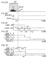
- shielding members 42, 44, 46, and 48 of a bridge beam or the like which shield a portion or the whole portion of a transmitted light are installed sequentially so as to be spaced apart from each other at the upper portion of a vehicle 40 in a traveling direction thereof (i.e., a direction indicated by arrow A of Fig. 2A ).
- a shielding state in which a portion or the whole portion of the transmitted light is shielded and a non-shielding state in which the transmitted light is not shielded are repeated alternatively.
- the outputting signal of the illumination sensor 36 outputs an electric signal representing a voltage or the like in accordance with the illumination of the incident light.
- a fixed illumination value S is used as a threshold value, and as shown in Fig 2B , when the illumination value is equal to or less than the illumination value S, the illumination sensor 36 outputs a low level signal S L .
- the illumination sensor 36 When the illumination value is equal to or more than the illumination value S, the illumination sensor 36 outputs a high level signal S H .
- This signal corresponds to a brightness pattern. Accordingly, when the low level signal S L is outputted, the outside of the vehicle 40 can be judged to be dark. When the high level signal S H is outputted, the outside of the vehicle 40 can be judged to be bright.
- t 1 to t 8 correspond to timings each of which is shifted from a shielded state in which a portion or the whole portion of the transmitted light is shielded by the shielding members to an non-shielded state in which a portion or the whole portion of the transmitted light is not shielded by the shielding members, when the vehicle passes beneath the shielding members 42 to 48.
- each of the timings t 1 to t 8 stands for a time when the vehicle enters into a shielded region or when the vehicle enters into a non-shielded region.
- a predetermined time is set as the time for switching over the lamp on the basis of the signal outputted from the illumination sensor 36 from the time at which a switching on/off signal is outputted from the illumination sensor 36 to the time at which the lamp is switched on/off.
- the predetermined time includes a switch-on delay time CHN, a switch-off delay time CTF, a switch-off extension time CFE, and an extension judgment time CPS, for which experimentally determined values are set previously.
- the switch-on delay time CHN is a time during which a signal is outputted from the illumination sensor 36 and the lamp is thereby switched on, and is provided so as not to occur any instant switch-on of the lamp at a micro shielded region.
- the switch-off delay time CTF is a time during which a signal is outputted from the illumination sensor 36 and the lamp is thereby switched off, and is provided so as not to occur any instant switch-off of the lamp at a micro non-shielded region.
- the switch-off extension time CFE is a time during which the actual switch-off of the lamp is extended at places where the vehicle exterior becomes light/ dark intermittently at the lower portion of the bridge beam, or on a road where a plurality of tunnels are successively formed, and is determined previously.
- the extension identification time CPS is a measurement setting time during which the places where the vehicle exterior becomes bright/dark intermittently are identified, and is previously determined.
- condition flags are used to express the brightness of the vehicle exterior.
- the condition flag is comprised of a non-set state which represents an initial state of a vehicle or an ordinary surrounding state of the vehicle (a reset state), Set 1 which represent a waiting state in which it is estimated that the vehicle exterior becomes bright/ dark intermittently (a level A state), and Set 2 which represents an intermittent state in which the place where the vehicle is traveling has a high possibility in that the vehicle exterior becomes bright/ dark intermittently (a level B).
- a condition flag is changed from a non-set state (a reset state) to Set 1state (a level A) in which the vehicle exterior is estimated to be bright/dark intermittently.
- the condition flag When the condition flag is set to Set 1 (a level A state), and the vehicle enters into the lower portion of the shielding member, the condition flag is changed from the Set 1(the level A state) to the Set 2 (a level B state) in which the place where the vehicle starts to travel may have a high possibility in that the vehicle exterior becomes bright/ dark intermittently.
- the time in which the switch-off extension time CFE is added to the switch-off delay time CTF is the time until the lamp is switched off.
- the illumination sensor 36 outputs a low level signal (S L ), and after the switch-on delay time CHN has been passed (time t 5A ), the lamp is switched on.
- the illumination sensor 36 outputs the high level signal S H .
- the switch-off delay time CTF has been passed (time t 6A )
- time until the lamp is switched off time t 6B
- the vehicle 40 passes through the lower portion of the gap between the shielding members 46 and 48, and enters into the lower portion of the shielding member 48 (time t 7 ) so that the switching-on of the lamp can be maintained.
- a terminal shielding member 50 for shielding a portion of the entire portion of the transmitted light from a bridge beam or the like is disposed at the upstream of the vehicle 40 in the traveling direction thereof (a direction indicated by arrow A).
- the transmitted light is set from a shielded state in which a portion or the entire portion of the light is shielded to a non-shielded state in which a portion or the entire portion of the light is not shielded.
- the outputting signal from the illumination sensor 36 is changed from the low level signal S L to the high level signal S H at the time when the vehicle 40 separates from the lower portion of the shielding member 50 (time t 9 ).
- the condition flag indicates Set 1 (level A state)
- the time by which the lamp is switched off is not extended. Accordingly, the lamp is switched off at the point of time when the switch-off delay time CTF (time t 9A ).
- the condition flag is set in a non-set state (reset state) from the point of time when the switch-off delay time CTF has been passed to the time when the extension judgment time CPS has been passed (time t 9D ) (time t 9 to t 9D :waiting observation time).
- the condition flag is changed.
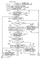
- Step 100 an initial setting is carried out. Namely, as described above, constants for the switch-on delay time CHN, the switch-off delay time CTF, the switch-off extension time CFE, and the extension judgment time CPS are set.
- the condition flag, a counter C, an a metering time t, T are reset.
- the counter C is a variable in order to count the switch-on frequency which will be described later.
- the metering time t is a variable for metering the above-described switch-on delay time CHN.
- the metering time T is a variable for metering the above-described switch-off delay time CTF, and the switch-off extension time CFE.
- Step 102 it is judged whether or not the signal outputted by the illumination sensor 36 is equal to or more than a predetermined value, i.e., a predetermined illumination value. Due to the judgment, it is thereby judged whether or not a vehicle has entered into the shaded portion.
- a predetermined value i.e., a predetermined illumination value. Due to the judgment, it is thereby judged whether or not a vehicle has entered into the shaded portion.
- the illumination value is more than a predetermined value
- the answer in Step 102 is "No"
- the judgment of the illumination value by the illumination sensor 36 is carried out again, and when the illumination is less than a predetermined value, the answer in Step 102 is "Yes”.
- Step 104 the timer 24 is reset.
- Step 106 it is judged whether or not the time t which is indicated by the timer 24 is t ⁇ CHN. Namely, it is judged whether the switch-on delay time CHN has been passed. When the switch-on delay time CHN has been judged to have elapsed, and the answer in Step 106 is "Yes". The routine proceeds to Step 110, where a lamp switch-on signal is transmitted to the drivers 32 and 34. Accordingly, the headlamps 28 and 30 are switched on. On the other hand, when the time t which is indicated by the timer 24 is t ⁇ CHN, the answer in Step 106 is "No".
- Step 108 is judged whether or not the signal outputted by the illumination sensor 36 is more than a predetermined value (a predetermined illumination value). Namely, it is thereby judged whether or not the vehicle has entered into the lighted portion. When the vehicle has entered into the lighted portion, the answer in Step 108 is "Yes”. The routine thereby returns to Step 102 without transmitting "switch on lamp" signal. When the vehicle has not entered into the lighted portion, the answer in Step 108 is "No", and the routine returns to Step 106.
- a predetermined value a predetermined illumination value
- Step 112 it is judged whether or not the signal outputted from the illumination sensor 36 is more than a predetermined value (a predetermined illumination value). Namely, it is judged whether or not the vehicle has entered into the lighted portion. When the vehicle does not enter into the lighted portion, the judgment in Step 112 is negative, and the illumination value outputted from the illumination sensor is judged once more. When the illumination value is more than the predetermined value, the judgment in Step 112 is affirmative. And in Step 114, the timer 24 is reset.
- a predetermined value a predetermined illumination value
- the routine proceeds to Step 122, where the switch-off delay time CTF is set for the switch-off time T, and thereafter, the routine goes to Step 124.
- Step 116 when the judgment is negative, the routine proceeds to Step 118, where it is judged whether or not the condition flag corresponds to Set 1.
- the condition flag is Set 1
- the routine goes to Step 122.
- condition flag F when the condition flag F is non-set or corresponds to Set 1, the switch-off delay time CTF is set for the switched off time T, and when the condition flag is Set 2, the sum of the switch-off delay time CTF and the switch-off extension time CFE is set for the switch-off time T.
- Step 124 it is judged whether or not the switch-off time T has been passed by judging whether or not the time t (indicated by the timer 24) ⁇ the switch off time T. When it is judged that the switch-off time T has been passed, the answer is affirmative in Step 124.
- Step 128, switch-off lamp signal is transmitted to the drivers 32 and 34. Accordingly, the headlamps are switched off. When the time t (indicated by the timer 24) is less than the switch-off time T, the answer is negative in Step 124.
- Step 126 it is judged whether or not the illumination value from the illumination sensor 36 is equal to or less than a predetermined illumination value. Namely, it is judged whether or not the vehicle has entered into the shaded portion.
- Step 126 When the vehicle has entered into the shaded portion, the answer in Step 126 is "Yes". The routine returns to Step 194 without outputting a switch off lam signal. In Step 126, when it has been judged that the vehicle has not entered into the shaded portion (negative judgment), the routine returns to Step 124.
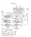
- Step 136 it is judged whether or not the extension judgment time CPS has been passed by judging whether or not the time t ⁇ CPS. When it is judged that the extension judgment time CPS has been passed, the answer is affirmative in Step 136.
- Step 150 the condition flag F and the counter C are reset, and the routine proceeds to Step 152.
- Step 152 it is judged whether or not a SW(switch) 26 is switched off. When the SW26 is switched on, the routine returns to Step 102, and when it is switched off, the present routine is terminated.
- Step 136 When it is judged that the time t has been passed by the extension judgment time CPS, the answer is negative in Step 136.
- Step 138 it is judged whether or not the illumination value by the illumination sensor 36. Accordingly, it is thereby judged whether or not the vehicle has entered into the shaded portion.
- the answer is affirmative in Step 138, and the routine proceeds to Step 140.
- the switch-on frequency is equal to or more than twice, in Step 142, the answer is "Yes", and the routine proceeds to Step 144.
- the switch-off time of the headlamp is extended by estimating that the shading is carried out intermittently. For this reason, even when the vehicle passes through the lower portion or the like of a bridge beam where the vehicle exterior becomes bright/ dark intermittently, the switching over of the headlamp is not needed, and the headlamp can remain switched on. As a result, the deterioration of the visibility for a driver can be prevented.
- the present invention is applied to the control of the switching on/ off of the headlamp.
- the present invention is not limited to this, and it can be applied to a lighting unit for illuminating tail lamps or meters.
- the present invention is shifted from an ordinary state to two states including a waiting state and an intermittent state.
- the present invention is not limited to this, and can be shifted to three states or more.
- the setting of the lamp has been classified into the ON state and the OFF state.
- the present invention is not limited to this, and can be sorted into a plurality of states on the basis of a plurality of the illumination values.
- the present invention is not limited to this.
- the control of switching on/off can be effected on the basis of the information from a communication device or other devices. For example, the judgment of the brightness pattern which is formed by alternating a shielded state and a non-shielded state, i.e., the standard for changing the condition flag or setting the extension time can be carried out.
- the present invention can be employed for a discharge light such as a metal halide lamp, a xenon lamp or the like.
- a discharge light such as a metal halide lamp, a xenon lamp or the like.
- HID high intensity discharge
Landscapes
- Engineering & Computer Science (AREA)
- Mechanical Engineering (AREA)
- Lighting Device Outwards From Vehicle And Optical Signal (AREA)
Claims (10)
- Unité d'éclairage pour véhicule (10), comprenant:un moyen de détection (36) qui détecte la luminosité de l'extérieur d'un véhicule;une lampe pour véhicule (28, 30) qui peut être installée audit véhicule, et a une source lumineuse pour illuminer au moins l'un de l'intérieur et de l'extérieur dudit véhicule; etun circuit de commande (12) qui exécute un processus de commande de commutation qui allume ladite lampe pour véhicule lorsque ladite luminosité détectée de l'extérieur du véhicule est inférieure ou égale à une valeur prédéterminée (S), et éteint ladite lampe pour véhicule lorsque la luminosité de l'extérieur du véhicule est supérieure à une valeur prédéterminée (S); un processus d'estimation qui estime si la luminosité de l'extérieur du véhicule qui entame son déplacement se trouve dans un état intermittent nécessitant de ce fait le maintien à l'état allumé de ladite lampe pour véhicule, sur la base de la variation de ladite luminosité détectée de l'extérieur du véhicule; et un processus prohibitif qui interdit l'extinction de ladite lampe pour véhicule lorsque ledit processus d'estimation estime que la luminosité dudit extérieur du véhicule se trouve dans ledit état intermittent;caractérisée en ce que
ledit processus d'estimation détermine à l'avance un modèle de luminosité dans lequel un état de MARCHE dans lequel ladite lampe pour véhicule est allumée lorsque ladite luminosité détectée de l'extérieur du véhicule est inférieure ou égale à une valeur prédéterminée, et un état d'ARRET dans lequel ladite lampe pour véhicule est éteinte lorsque ladite luminosité détectée de l'extérieur du véhicule est supérieure à une valeur prédéterminée s'alternent continuellement, et estime si la luminosité de l'extérieur du véhicule se trouve dans ledit état intermittent sur la base dudit modèle de luminosité prédéterminé. - Unité d'éclairage pour véhicule selon la revendication 1, dans laquelle ledit processus prohibitif annule l'interdiction de l'extinction de ladite lampe pour véhicule lorsque ledit moyen d'estimation estime que la luminosité de l'extérieur du véhicule ne se trouve pas dans un état intermittent.
- Unité d'éclairage pour véhicule selon la revendication 1, dans laquelle ledit circuit de commande comprend:un moyen de commande de commutation (26) destiné à exécuter ledit processus de commande de commutation,un moyen d'estimation destiné à exécuter ledit processus d'estimation, etun moyen prohibitif destiné à exécuter ledit processus prohibitif.
- Unité d'éclairage pour véhicule selon la revendication 1 ou 3, dans laquelle ledit processus d'estimation estime si la luminosité de l'extérieur du véhicule se trouve dans ledit état intermittent en comparant le modèle de luminosité résultant de ladite luminosité détectée de l'extérieur du véhicule audit modèle de luminosité prédéterminé.
- Unité d'éclairage pour véhicule selon la revendication 1 ou 3, dans laquelle ledit processus d'estimation inclut: un processus de réglage qui règle un mode d'attente dans lequel on estime que la luminosité de l'extérieur du véhicule est dans ledit état intermittent, lorsque la luminosité de l'extérieur du véhicule a un modèle dans lequel ledit état de MARCHE est réglé au premier nombre de fois ou plus au sein d'un temps prédéterminé, et tandis que ledit mode d'attente est en train d'être réglé, qui règle un mode intermittent lorsque la luminosité de l'extérieur du véhicule a un modèle dans lequel ledit état de MARCHE est réglé au deuxième nombre de fois ou plus au sein d'un temps prédéterminé,
de sorte que ledit processus d'estimation estime que la luminosité de l'extérieur du véhicule se trouve dans ledit état intermittent lorsqu'un mode intermittent a été réglé par ledit processus de réglage. - Unité d'éclairage pour véhicule selon la revendication 5, dans laquelle ledit processus de réglage annule ledit mode d'attente lorsque la luminosité de l'extérieur du véhicule passe à un état d'ARRET en raison de la variation de celle-ci et qu'un temps d'observation d'attente prédéterminé (CPS) s'est écoulé alors qu'on se trouve dans ledit mode d'attente.
- Unité d'éclairage pour véhicule selon la revendication 5 ou 6, dans laquelle ledit processus de réglage annule ledit mode intermittent et règle ledit mode d'attente, lorsque la luminosité de l'extérieur du véhicule passe à un état d'ARRET en raison de la variation de celle-ci et qu'un temps d'observation d'attente intermittente prédéterminé s'est écoulé alors qu'on se trouve dans ledit mode intermittent.
- Unité d'éclairage pour véhicule selon l'une quelconque des revendications 5 à 7, dans laquelle ledit processus de réglage règle ledit mode d'attente ou ledit mode intermittent en réglant ou en réinitialisant un drapeau de condition.
- Unité d'éclairage pour véhicule selon l'une quelconque des revendications 1 à 8, dans laquelle ladite source lumineuse est une lampe à décharge.
- Unité d'éclairage pour véhicule selon l'une quelconque des revendications 1 à 9, dans laquelle ledit processus de commande de commutation allume/éteint la lampe du véhicule de sorte que la lampe du véhicule soit allumée après qu'un temps de mise en marche (CHN) s'est écoulé depuis l'instant où ladite luminosité détectée de l'extérieur du véhicule est inférieure ou égale à une valeur prédéterminée, et la lampe du véhicule est éteinte après qu'un temps d'extinction (CTF) s'est écoulé depuis l'instant où ladite luminosité détectée de l'extérieur du véhicule est supérieure à une valeur prédéterminée.
Applications Claiming Priority (3)
| Application Number | Priority Date | Filing Date | Title |
|---|---|---|---|
| JP198975/97 | 1997-07-24 | ||
| JP19897597A JP3149823B2 (ja) | 1997-07-24 | 1997-07-24 | 車両用照明装置 |
| JP19897597 | 1997-07-24 |
Publications (3)
| Publication Number | Publication Date |
|---|---|
| EP0893304A2 EP0893304A2 (fr) | 1999-01-27 |
| EP0893304A3 EP0893304A3 (fr) | 2003-03-26 |
| EP0893304B1 true EP0893304B1 (fr) | 2008-04-09 |
Family
ID=16400048
Family Applications (1)
| Application Number | Title | Priority Date | Filing Date |
|---|---|---|---|
| EP98113649A Expired - Lifetime EP0893304B1 (fr) | 1997-07-24 | 1998-07-22 | Unité d'éclairage pour véhicule |
Country Status (4)
| Country | Link |
|---|---|
| US (1) | US6014207A (fr) |
| EP (1) | EP0893304B1 (fr) |
| JP (1) | JP3149823B2 (fr) |
| DE (1) | DE69839331T2 (fr) |
Families Citing this family (17)
| Publication number | Priority date | Publication date | Assignee | Title |
|---|---|---|---|---|
| JP2001339047A (ja) | 2000-05-29 | 2001-12-07 | Matsushita Electric Ind Co Ltd | 半導体装置 |
| US6711481B1 (en) * | 2000-08-18 | 2004-03-23 | Ford Global Technologies, Llc | System and method for programming an exit delay for automatic headlamps |
| AU2003298558A1 (en) * | 2002-08-21 | 2004-05-04 | Gentex Corporation | Image acquisition and processing methods for automatic vehicular exterior lighting control |
| DE102006018667A1 (de) * | 2006-04-21 | 2007-10-25 | Audi Ag | Kraftfahrzeug mit einem Fernlichtassistenzsystem |
| DE102006026738B4 (de) * | 2006-06-08 | 2020-03-12 | Continental Automotive Gmbh | Verfahren und Steuersystem zur Steuerung der Leuchtleistung zumindest einer Leuchte in einem Fahrzeug |
| JP2008114655A (ja) * | 2006-11-01 | 2008-05-22 | Denso Corp | 車両用照明制御装置 |
| JP4678536B2 (ja) * | 2007-10-01 | 2011-04-27 | 株式会社デンソー | 照度センサ |
| JP4952644B2 (ja) * | 2008-04-21 | 2012-06-13 | 株式会社デンソー | 車両用灯火制御装置 |
| US8933627B2 (en) * | 2012-03-08 | 2015-01-13 | GM Global Technology Operations LLC | Systems and methods for controlling vehicle lighting |
| JP5928077B2 (ja) * | 2012-03-28 | 2016-06-01 | 株式会社デンソー | ライト制御装置、およびライト制御プログラム |
| PL2913581T3 (pl) * | 2013-02-04 | 2018-05-30 | Wen-Sung Lee | Inteligentne urządzenie oświetlające do pojazdu |
| CN103661082B (zh) * | 2013-12-12 | 2015-12-30 | 广东菲柯特电子科技有限公司 | 一种车灯光感自动调节延时装置 |
| WO2015181752A1 (fr) * | 2014-05-28 | 2015-12-03 | Nice S.R.L. | Accessoire pour véhicules pour l'automatisation de faisceaux principaux doté d'un système électronique permettant de réduire les perturbations optiques |
| KR101614932B1 (ko) * | 2015-10-06 | 2016-04-25 | 콘티넨탈 오토모티브 게엠베하 | 자동차의 상향등 제어장치 및 그 방법 |
| ES2900699A1 (es) * | 2020-09-17 | 2022-03-17 | Cecotec Res And Development Sl | Sistema de iluminación adaptativo y método asociado para vehículo de movilidad personal |
| JP7415994B2 (ja) * | 2021-03-22 | 2024-01-17 | 株式会社デンソー | 車両制御装置、車両制御方法 |
| US11691698B2 (en) | 2021-11-12 | 2023-07-04 | Daniel Scott Trotter | Safety lighting system for watercraft |
Family Cites Families (4)
| Publication number | Priority date | Publication date | Assignee | Title |
|---|---|---|---|---|
| US4613791A (en) * | 1984-02-02 | 1986-09-23 | Honda Motor Co., Ltd. | Automatic light control apparatus for vehicle |
| JPH05147469A (ja) * | 1991-11-29 | 1993-06-15 | Suzuki Motor Corp | ヘツドランプ調光装置 |
| JP3670671B2 (ja) * | 1992-09-24 | 2005-07-13 | ペンタックス テクノロジーズ コーポレーション | 光源調整制御方法、及び、光源調整制御装置 |
| DE19523262A1 (de) * | 1995-06-27 | 1997-01-02 | Bosch Gmbh Robert | Einrichtung zur automatischen Schaltung von Beleuchtungseinrichtungen bei Fahrzeugen |
-
1997
- 1997-07-24 JP JP19897597A patent/JP3149823B2/ja not_active Expired - Fee Related
-
1998
- 1998-07-17 US US09/116,664 patent/US6014207A/en not_active Expired - Lifetime
- 1998-07-22 EP EP98113649A patent/EP0893304B1/fr not_active Expired - Lifetime
- 1998-07-22 DE DE69839331T patent/DE69839331T2/de not_active Expired - Lifetime
Also Published As
| Publication number | Publication date |
|---|---|
| DE69839331D1 (de) | 2008-05-21 |
| JPH1134735A (ja) | 1999-02-09 |
| US6014207A (en) | 2000-01-11 |
| DE69839331T2 (de) | 2009-07-16 |
| EP0893304A3 (fr) | 2003-03-26 |
| EP0893304A2 (fr) | 1999-01-27 |
| JP3149823B2 (ja) | 2001-03-26 |
Similar Documents
| Publication | Publication Date | Title |
|---|---|---|
| US6014207A (en) | Vehicle lighting unit | |
| EP1555157B1 (fr) | Dispositif de commande de lumière d'un véhicule | |
| US5374852A (en) | Motor vehicle headlight activation apparatus for inclement weather conditions | |
| US11603034B2 (en) | Vehicle lighting apparatus | |
| US20130320193A1 (en) | System and method for controlling vehicle equipment responsive to a multi-stage village detection | |
| KR100746159B1 (ko) | 차량 조명장치를 자동으로 스위칭하기 위한 장치 | |
| US7378753B2 (en) | Vehicular automatic light control apparatus | |
| KR100781909B1 (ko) | 자동차의 조명 장치를 자동적으로 스위칭하기 위한 장치 | |
| US6051931A (en) | Work lamp on-off control circuit | |
| JP2002347511A (ja) | 制動灯制御装置 | |
| WO2004060716A1 (fr) | Systeme d'eclairage pour un vehicule | |
| JPS5871230A (ja) | 車両用ヘツドライトコントロ−ル装置 | |
| JPH1097897A (ja) | トンネル内照明制御システム | |
| JP2004243895A (ja) | 自動灯火装置 | |
| JP2007245883A (ja) | 灯火類消点灯制御装置及び制御方法 | |
| KR20050071092A (ko) | 주위 환경에 대응하는 자동차용 램프 시스템 | |
| KR970004732B1 (ko) | 자동차의 전조등 제어회로 | |
| JP2871336B2 (ja) | 車両用前照灯装置 | |
| KR0173358B1 (ko) | 전도등 밝기 조절장치 | |
| JPH0218128A (ja) | 車両照明装置の点灯制御装置 | |
| KR960002863B1 (ko) | 차량의 광량감지 후미 경고등 자동 점등장치 | |
| JP2004235795A (ja) | 車両用電気機器の表示装置 | |
| KR100427233B1 (ko) | 차량위치 인식램프 제어장치 | |
| KR0167918B1 (ko) | 자동 전조등 장치 및 그 작동방법 | |
| KR19980066753A (ko) | 자동차의 후미등과 안개등 밝기 조절 장치 |
Legal Events
| Date | Code | Title | Description |
|---|---|---|---|
| PUAI | Public reference made under article 153(3) epc to a published international application that has entered the european phase |
Free format text: ORIGINAL CODE: 0009012 |
|
| 17P | Request for examination filed |
Effective date: 19980723 |
|
| AK | Designated contracting states |
Kind code of ref document: A2 Designated state(s): AT BE CH CY DE DK ES FI FR GB GR IE IT LI LU MC NL PT SE |
|
| AX | Request for extension of the european patent |
Free format text: AL;LT;LV;MK;RO;SI |
|
| PUAL | Search report despatched |
Free format text: ORIGINAL CODE: 0009013 |
|
| AK | Designated contracting states |
Kind code of ref document: A3 Designated state(s): AT BE CH CY DE DK ES FI FR GB GR IE IT LI LU MC NL PT SE Designated state(s): AT BE CH CY DE DK ES FI FR GB GR IE IT LI LU MC NL PT SE |
|
| AX | Request for extension of the european patent |
Extension state: AL LT LV MK RO SI |
|
| AKX | Designation fees paid |
Designated state(s): DE FR GB |
|
| 17Q | First examination report despatched |
Effective date: 20070430 |
|
| GRAP | Despatch of communication of intention to grant a patent |
Free format text: ORIGINAL CODE: EPIDOSNIGR1 |
|
| RIN1 | Information on inventor provided before grant (corrected) |
Inventor name: KAMIYA, MASACHIKA Inventor name: SUZUKI, TOMONORI |
|
| GRAS | Grant fee paid |
Free format text: ORIGINAL CODE: EPIDOSNIGR3 |
|
| GRAA | (expected) grant |
Free format text: ORIGINAL CODE: 0009210 |
|
| AK | Designated contracting states |
Kind code of ref document: B1 Designated state(s): DE FR GB |
|
| REG | Reference to a national code |
Ref country code: GB Ref legal event code: FG4D |
|
| REF | Corresponds to: |
Ref document number: 69839331 Country of ref document: DE Date of ref document: 20080521 Kind code of ref document: P |
|
| ET | Fr: translation filed | ||
| PLBE | No opposition filed within time limit |
Free format text: ORIGINAL CODE: 0009261 |
|
| STAA | Information on the status of an ep patent application or granted ep patent |
Free format text: STATUS: NO OPPOSITION FILED WITHIN TIME LIMIT |
|
| 26N | No opposition filed |
Effective date: 20090112 |
|
| REG | Reference to a national code |
Ref country code: GB Ref legal event code: 746 Effective date: 20091103 |
|
| REG | Reference to a national code |
Ref country code: FR Ref legal event code: PLFP Year of fee payment: 19 |
|
| REG | Reference to a national code |
Ref country code: FR Ref legal event code: PLFP Year of fee payment: 20 |
|
| PGFP | Annual fee paid to national office [announced via postgrant information from national office to epo] |
Ref country code: FR Payment date: 20170613 Year of fee payment: 20 |
|
| PGFP | Annual fee paid to national office [announced via postgrant information from national office to epo] |
Ref country code: DE Payment date: 20170719 Year of fee payment: 20 Ref country code: GB Payment date: 20170719 Year of fee payment: 20 |
|
| REG | Reference to a national code |
Ref country code: DE Ref legal event code: R071 Ref document number: 69839331 Country of ref document: DE |
|
| REG | Reference to a national code |
Ref country code: GB Ref legal event code: PE20 Expiry date: 20180721 |
|
| PG25 | Lapsed in a contracting state [announced via postgrant information from national office to epo] |
Ref country code: GB Free format text: LAPSE BECAUSE OF EXPIRATION OF PROTECTION Effective date: 20180721 |