EP0893335B1 - Poignée tournante pour un organe de commande de bicyclette - Google Patents
Poignée tournante pour un organe de commande de bicyclette Download PDFInfo
- Publication number
- EP0893335B1 EP0893335B1 EP98113714A EP98113714A EP0893335B1 EP 0893335 B1 EP0893335 B1 EP 0893335B1 EP 98113714 A EP98113714 A EP 98113714A EP 98113714 A EP98113714 A EP 98113714A EP 0893335 B1 EP0893335 B1 EP 0893335B1
- Authority
- EP
- European Patent Office
- Prior art keywords
- grip
- peripheral surface
- rotatable member
- recesses
- handgrip according
- Prior art date
- Legal status (The legal status is an assumption and is not a legal conclusion. Google has not performed a legal analysis and makes no representation as to the accuracy of the status listed.)
- Expired - Lifetime
Links
Images

Classifications
-
- B—PERFORMING OPERATIONS; TRANSPORTING
- B62—LAND VEHICLES FOR TRAVELLING OTHERWISE THAN ON RAILS
- B62K—CYCLES; CYCLE FRAMES; CYCLE STEERING DEVICES; RIDER-OPERATED TERMINAL CONTROLS SPECIALLY ADAPTED FOR CYCLES; CYCLE AXLE SUSPENSIONS; CYCLE SIDECARS, FORECARS, OR THE LIKE
- B62K23/00—Rider-operated controls specially adapted for cycles, i.e. means for initiating control operations, e.g. levers, grips
- B62K23/02—Rider-operated controls specially adapted for cycles, i.e. means for initiating control operations, e.g. levers, grips hand actuated
- B62K23/04—Twist grips
-
- B—PERFORMING OPERATIONS; TRANSPORTING
- B62—LAND VEHICLES FOR TRAVELLING OTHERWISE THAN ON RAILS
- B62L—BRAKES SPECIALLY ADAPTED FOR CYCLES
- B62L1/00—Brakes; Arrangements thereof
-
- B—PERFORMING OPERATIONS; TRANSPORTING
- B62—LAND VEHICLES FOR TRAVELLING OTHERWISE THAN ON RAILS
- B62L—BRAKES SPECIALLY ADAPTED FOR CYCLES
- B62L1/00—Brakes; Arrangements thereof
- B62L1/02—Brakes; Arrangements thereof in which cycle wheels are engaged by brake elements
- B62L1/06—Brakes; Arrangements thereof in which cycle wheels are engaged by brake elements the wheel rim being engaged
- B62L1/10—Brakes; Arrangements thereof in which cycle wheels are engaged by brake elements the wheel rim being engaged by the elements moving substantially parallel to the wheel axis
- B62L1/14—Brakes; Arrangements thereof in which cycle wheels are engaged by brake elements the wheel rim being engaged by the elements moving substantially parallel to the wheel axis the elements being mounted on levers pivotable about different axes
-
- Y—GENERAL TAGGING OF NEW TECHNOLOGICAL DEVELOPMENTS; GENERAL TAGGING OF CROSS-SECTIONAL TECHNOLOGIES SPANNING OVER SEVERAL SECTIONS OF THE IPC; TECHNICAL SUBJECTS COVERED BY FORMER USPC CROSS-REFERENCE ART COLLECTIONS [XRACs] AND DIGESTS
- Y10—TECHNICAL SUBJECTS COVERED BY FORMER USPC
- Y10T—TECHNICAL SUBJECTS COVERED BY FORMER US CLASSIFICATION
- Y10T74/00—Machine element or mechanism
- Y10T74/20—Control lever and linkage systems
- Y10T74/20207—Multiple controlling elements for single controlled element
- Y10T74/20256—Steering and controls assemblies
- Y10T74/20268—Reciprocating control elements
- Y10T74/2028—Handle bar type
- Y10T74/20287—Flexible control element
-
- Y—GENERAL TAGGING OF NEW TECHNOLOGICAL DEVELOPMENTS; GENERAL TAGGING OF CROSS-SECTIONAL TECHNOLOGIES SPANNING OVER SEVERAL SECTIONS OF THE IPC; TECHNICAL SUBJECTS COVERED BY FORMER USPC CROSS-REFERENCE ART COLLECTIONS [XRACs] AND DIGESTS
- Y10—TECHNICAL SUBJECTS COVERED BY FORMER USPC
- Y10T—TECHNICAL SUBJECTS COVERED BY FORMER US CLASSIFICATION
- Y10T74/00—Machine element or mechanism
- Y10T74/20—Control lever and linkage systems
- Y10T74/20576—Elements
- Y10T74/20732—Handles
- Y10T74/2078—Handle bars
- Y10T74/20828—Handholds and grips
Definitions
- the present invention is directed to bicycle control devices and, more particularly, to a grip for a twist-grip shift control device which conforms more closely to a rider's hand.
- Twist-grip shift control devices are sometimes used to control various types of bicycle transmissions. Examples of such devices are disclosed in JP 44-26571; USP 3,633437; USP 4,900,291 and USP 5,197,927. Also from EP 0 759 393 Al a speed change operating device for a bicycle is known to operate a front or a rear derailleur of a bicycle. Such devices typically include a generally annular rotatable member that is mounted around the bicycle handlebar coaxially with the handlebar axis, wherein rotation of the rotatable member with the palm of the hand controls the pulling and releasing of the transmission control cable.
- the US 3,344,684 provides a plastic grip for the handlebar of a bicycle, of a motorcycle or the like which is formed by an inner shell and an outer shell which are spaced from each other to provide a body which flexes inwardly when grasped to provide a dampening effect while riding the bicycle.
- a rotatable handgrip for a twist-grip shift control device includes a rotatable member and a flexible grip disposed over the rotatable member.
- One or more spaces are defined between an inner peripheral surface of the grip and an outer peripheral surface of the rotatable member so that the grip bends radially inwardly in response to pressure from a hand part (palm, finger, thumb, etc.) so as to generally conform to the hand part.
- the space may be formed by a recess formed on the inner peripheral surface of the grip, on the outer peripheral surface of the rotatable member, a combination of recesses on the grip and the rotatable member, or through some other means.
- a rotatable grip constructed according to the present invention increases traction between the palm of the hand and the rotatable grip without requiring ribs or nubs.
- the present invention also may be employed advantageously in a handgrip which uses ribs and nubs, because the space between the grip and the rotatable member allow the ribs and nubs to yield to the pressure of the rider's hand. This, in turn, reduces or eliminates the incidences of pain and fatigue.
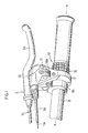
- Figure 1 is an oblique view of a particular embodiment of a twist-grip shift control device 10 according to the present invention mounted together with a brake lever assembly 9.
- shift control device 10 includes a housing 12 mounted around a handlebar 8, a rotatable handgrip 16 structured for rotation around an axis X coaxial with handlebar 8, a pulley 21 for pulling and releasing an inner wire 11a of control cable 11, and a pulley retaining member 28 for retaining pulley 21 to housing 12.
- Pulley retaining member 28 may include a framed opening 28a for selectively displaying a numeral disposed on pulley 21 indicating the currently selected gear.
- a motion transmitting mechanism (not shown) is disposed between rotatable handgrip 16 and pulley 21 for transmitting rotation of handgrip 16 to pulley 21.
- the motion transmitting mechanism may be constructed, for example, according to copending U.S. patent application number 08/854,520 filed May 12, 1997 entitled “Bicycle Shift Control Device” by Takuro Yamane and incorporated herein by reference. Since the motion transmitting mechanism does not form a part of the present invention, a detailed description of that mechanism shall be omitted.
- Brake lever assembly 9 includes a brake lever 9a pivotably mounted to a brake lever bracket 9b which, in turn, is mounted around handlebar 8 in close proximity to (e.g., adjacent) housing 12 of shift control device 10. Brake lever 9a is connected to a brake control cable 9c for controlling a brake device in a conventional manner.
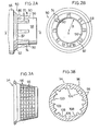
- handgrip 16 includes a rotatable member 50 and a flexible grip 54.
- rotatable member 50 includes a generally cylindrical main body 56 having an outer peripheral surface 58; a generally frustoconical intermediate portion 62, and a larger generally cylindrical portion 66 which interfaces with the motion transmitting mechanism within housing 12.
- a plurality of grip engaging members in the form of ribs 70 elongated in the direction of the handlebar axis X extend radially outwardly from outer peripheral surface 58 of main body 56.
- ribs 70 are evenly spaced in the circumferential direction of outer peripheral surface 58.
- Each rib includes a pair of side surfaces 74 that extend from a side surface 82 of frustoconical portion 62 in the direction of the handlebar axis X, and a top surface 86 that inclines slightly radially inwardly from side surface 82 of frustoconical portion 62 to a rib end surface 90 located at an intermediate portion of outer peripheral surface 58.
- the plurality of ribs 70 define a corresponding plurality of valleys 94 disposed between each pair of adjacent ribs 70, where the bottom floor 92 of each valley 94 is formed by outer peripheral surface 58 of main body 56.
- outer peripheral surface 58 has a constant radius of curvature R from handlebar axis X along its entire axial length so that outer peripheral surface 58 has the shape of a straight cylinder.
- the floor 92 of each valley 94 likewise has a constant radius of curvature as shown in Figure 2B.
- flexible grip 54 snugly fits around outer peripheral surface 58 of rotatable member 50, and an outer peripheral surface 96 of grip 54 includes a plurality of gripping projections 98 to further facilitate traction between the rider's hand and grip 54 (and hence ) rotatable handgrip 16.
- the inner peripheral surface 100 of grip 54 includes a plurality of rotatable member engaging recesses 104 that are evenly spaced in the circumferential direction of inner peripheral surface 100. Each rotatable member engaging recess 104 is shaped for snugly fitting to a corresponding rib 70 so that grip 54 is nonrotatably secured to rotatable member 50.
- a plurality of recesses 108 disposed between spaced apart pairs of inner peripheral surface portions 109 likewise are evenly spaced along the inner peripheral surface of grip 54.
- Each recesses 108 cooperates with a corresponding valley floor 92 for forming a plurality of spaces 110 as shown in Figure 4.
- Inner peripheral surface portions 109 are disposed adjacent to their corresponding ribs 70 and contact both the rib 70 and the adjacent valley floor 92 to snugly fit grip 54 to rotatable member 50.
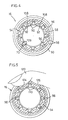
- Figure 5 is a side cross sectional view of the rotatable member 50 and flexible grip 54 illustrating how the flexible grip 54 bends in response to a gripping force exerted by a hand.
- a finger 120 presses radially inwardly to firmly grasp rotatable grip 16.
- the portions of grip 54 disposed over spaces 110 form dents 124 and 126 which conform to finger 120 in response to the radially inwardly directed pressure of finger 120.
- the portions of grip 54 disposed over spaces 110 bend radially inwardly as shown in Figure 5 for partially or substantially reducing the volume of the corresponding space 110.
- dents 124 and 126 enhance the traction between the rider's hand and rotatable handgrip 16 by conforming more closely to the rider's hand. Also, there are no sharp edges jamming into the rider's hand as in the prior art rib/nub designs. Furthermore, the yielding nature of grip 54 also cushions the rider's hand to avoid the excessive pressures caused by prior art rib/nub designs, thus further reducing the risk of pain or fatigue.
- Figure 6 is a side cross sectional view of an alternative embodiment of a rotatable handgrip 16A according to the present invention using a different rotatable member 50A and flexible grip 54A.
- grip 54A includes a plurality of rotatable member engaging members 55A projecting radially inwardly from the inner peripheral surface 100A.
- Rotatable member 50A includes a plurality of grip engaging recesses 57A formed in outer peripheral surface 58A, wherein each rotatable member engaging member 55A is disposed in a corresponding grip engaging recess 57A.
- a plurality of recesses 108A disposed between adjacent pairs of rotatable member engaging members 55A are evenly spaced along the inner peripheral surface 100A of grip 54A.
- Each recess 108A cooperates with a corresponding portion of the outer peripheral surface 58A of rotatable member 50A for forming a plurality of spaces 110A that function in the same manner as spaces 110 in the first embodiment.
- Figure 7 is a side cross sectional view of another alternative embodiment of a rotatable handgrip 16B according to the present invention using a different rotatable member 50B and flexible grip 54B.
- the rotatable member 50B includes a plurality of grip engaging members in the form of ribs 70B projecting radially outwardly from the outer peripheral surface 58B
- the grip 54B includes a corresponding plurality of rotatable member engaging recess 104B
- each grip engaging member 70B is disposed in a corresponding rotatable member engaging recess 104B.
- grip 54B does not have recesses corresponding to recesses 108 in the first embodiment.
- a plurality of evenly spaced recesses 150 are formed in the outer peripheral surface 58B of rotatable member 50B. Each recess 150 cooperates with the inner peripheral surface 100B of grip 54B for forming a plurality of spaces 110B that function in the same manner as spaces 110 in the first embodiment.
- Figure 8 is a side cross sectional view of another alternative embodiment of a rotatable handgrip 16C according to the present invention using a different rotatable member 50C and flexible grip 54C.
- the grip 54C includes a plurality of rotatable member engaging members 55C projecting radially inwardly from the inner peripheral surface 100C
- the rotatable member 50C includes a plurality of grip engaging recesses 57C formed in the outer peripheral surface 58C
- each rotatable member engaging member 55C is disposed in a corresponding grip engaging recess 57C.
- a plurality of evenly spaced recesses 150C are formed in the outer peripheral surface 58C of rotatable member 50C.
- Each recess 150C cooperates with the inner peripheral surface 100C of grip 54C for forming a plurality of spaces 110C that function in the same manner as spaces 110 in the first embodiment.
Landscapes
- Engineering & Computer Science (AREA)
- Mechanical Engineering (AREA)
- Steering Devices For Bicycles And Motorcycles (AREA)
- Arrangement Or Mounting Of Control Devices For Change-Speed Gearing (AREA)
- Mechanical Control Devices (AREA)
Claims (26)
- Poignée tournante (16, 16A) pour un organe de commande de bicyclette comprenant :caractérisée en ce qu'un espace (110, 110A) est défini entre une surface périphérique intérieure de la poignée (54, 54A) et une surface périphérique extérieure de l'élément tournant (50, 50A) de telle manière que la poignée (54, 54A) s'enfonce radialement vers l'intérieur en réponse à la pression d'une partie de main de façon à se conformer globalement à la partie de main ; et dans laquelle un évidement (108, 108A) est formé sur la surface périphérique intérieure de la poignée (54, 54A) pour former l'espace (110, 110A).un élément tournant (50, 50A), etune poignée flexible (54, 54A) disposée sur l'élément tournant (50, 50A),
- Poignée tournante (16B, 16C) pour un organe de commande de bicyclette comprenant :caractérisée en ce qu'un espace (110B, 110C) est défini entre une surface périphérique intérieure de la poignée (54B, 54C) et une surface périphérique extérieure de l'élément tournant (50B, 50C) de telle manière que la poignée (54B, 54C) s'enfonce radialement vers l'intérieur en réponse à la pression d'une partie de main de façon à se conformer globalement à la partie de main ; et dans laquelle un évidement (150) est formé sur la surface périphérique extérieure de l'élément tournant pour former l'espace (110B, 110C).un élément tournant (50B, 50C), etune poignée flexible (54B, 54C) disposée sur l'élément tournant (50B, 50C),
- Poignée selon la revendication 1 ou 2, caractérisée en ce que la poignée (54, 54A, 54B, 54C) se courbe radialement vers l'intérieur dans l'espace (110, 110A, 110B, 110C) en réponse à la pression de la partie de la main.
- Poignée selon la revendication 1 ou 3, caractérisée en ce qu'une pluralité des évidements (108, 108A) sont formés sur la surface périphérique intérieure de la poignée (54, 54A) pour former une pluralité d'espaces.
- Poignée selon la revendication 4, caractérisée en ce que la pluralité d'évidements (108, 108A) sont disposés régulièrement le long de la surface périphérique intérieure de la poignée (54, 54A).
- Poignée selon l'une quelconque des revendications 1 à 5, caractérisée en ce que l'élément tournant (50) comporte un élément venant en prise avec la poignée faisant saillie radialement vers l'extérieur depuis la surface périphérique extérieure, dans laquelle la poignée comprend un évidement venant en prise avec l'élément tournant, et dans lequel l'élément venant en prise avec la poignée est disposé dans l'évidement venant en prise avec l'élément tournant.
- Poignée selon l'une quelconque des revendications 1 à 5, caractérisée en ce que la poignée comprend un élément venant en prise avec l'élément tournant faisant saillie radialement vers l'intérieur depuis la surface périphérique intérieure, dans laquelle l'élément tournant comprend un évidement venant en prise avec la poignée, et dans laquelle l'élément venant en prise avec l'élément tournant est disposé dans l'évidement venant en prise avec la poignée.
- Poignée selon l'une quelconque des revendications 1 à 5, caractérisée en ce que l'élément tournant comprend une pluralité de nervures allongées faisant saillie radialement vers l'extérieur depuis la surface périphérique extérieure, dans laquelle la poignée comprend une pluralité d'évidements venant en prise avec l'élément tournant, et dans laquelle la pluralité de nervures sont disposées dans les évidements correspondants de la pluralité d'évidements venant en prise avec l'élément tournant.
- Poignée selon la revendication 8, caractérisée en ce qu'une pluralité des évidements sont formés sur la surface périphérique intérieure de la poignée pour former une pluralité des espaces.
- Poignée selon la revendication 9, caractérisée en ce que la pluralité de nervures sont disposées régulièrement dans une direction circonférentielle le long de la surface périphérique extérieure de l'élément tournant.
- Poignée selon la revendication 10, caractérisée en ce que la pluralité d'évidements sont disposés régulièrement dans la direction circonférentielle le long de la surface périphérique intérieure de la poignée.
- Poignée selon la revendication 11, caractérisée en ce qu'un seul évidement est disposé entre chaque paire adjacente de la pluralité de nervures.
- Poignée selon la revendication 1 ou 2, caractérisée en ce que la poignée comprend une pluralité de nervures allongée faisant saillie radialement vers l'intérieur depuis la surface périphérique intérieure, dans laquelle l'élément tournant comprend une pluralité d'évidements venant en prise avec la poignée, et dans laquelle la pluralité de nervures sont disposées dans des évidements correspondants de la pluralité d'évidements venant en prise avec la poignée.
- Poignée selon la revendication 13, caractérisée en ce qu'une pluralité des évidements sont formés sur la surface périphérique intérieure de la poignée pour former une pluralité des espaces.
- Poignée selon la revendication 14, caractérisée en ce que la pluralité de nervures sont disposées régulièrement dans une direction circonférentielle le long de la surface périphérique intérieure de la poignée.
- Poignée selon la revendication 15, caractérisée en ce que la pluralité d'évidements sont disposés régulièrement dans la direction circonférentielle le long de la surface périphérique intérieure de la poignée.
- Poignée selon la revendication 2, caractérisée en ce qu'une pluralité des évidements sont formés sur la surface périphérique extérieure de l'élément tournant (50B, 50C) pour former une pluralité d'espaces.
- Poignée selon la revendication 17, caractérisée en ce que la pluralité d'évidements sont disposés régulièrement le long de la surface périphérique extérieure de l'élément tournant.
- Poignée selon la revendication 8, caractérisée en ce qu'une pluralité des évidements sont formés sur la surface périphérique extérieure de l'élément tournant pour former une pluralité des espaces.
- Poignée selon la revendication 19, caractérisée en ce que la pluralité de nervures sont disposées régulièrement dans une direction circonférentielle le long de la surface périphérique extérieure de l'élément tournant.
- Poignée selon la revendication 20, caractérisée en ce que la pluralité d'évidements sont disposés régulièrement dans une direction circonférentielle le long de la surface périphérique extérieure de l'élément tournant.
- Poignée selon la revendication 21, caractérisée en ce qu'un seul évidement est disposé entre chaque paire adjacente de la pluralité de nervures.
- Poignée selon la revendication 13, caractérisée en ce qu'une pluralité des évidements sont formés sur la surface périphérique extérieure de l'élément tournant pour former une pluralité des espaces.
- Poignée selon la revendication 23, caractérisée en ce que la pluralité de nervures sont disposées régulièrement dans une direction circonférentielle le long de la surface périphérique intérieure de la poignée.
- Poignée selon la revendication 24, caractérisée en ce que la pluralité d'évidements sont disposés régulièrement dans la direction circonférentielle le long de la surface périphérique extérieure de l'élément tournant.
- Poignée selon la revendication 15 ou 25, caractérisée en ce qu'un seul évidement est disposé entre chaque paire adjacente de la pluralité de nervures.
Applications Claiming Priority (2)
| Application Number | Priority Date | Filing Date | Title |
|---|---|---|---|
| US900935 | 1997-07-25 | ||
| US08/900,935 US6101895A (en) | 1997-07-25 | 1997-07-25 | Grip for a bicycle shift control device |
Publications (4)
| Publication Number | Publication Date |
|---|---|
| EP0893335A2 EP0893335A2 (fr) | 1999-01-27 |
| EP0893335A3 EP0893335A3 (fr) | 2000-07-19 |
| EP0893335B1 true EP0893335B1 (fr) | 2004-04-14 |
| EP0893335B2 EP0893335B2 (fr) | 2009-03-25 |
Family
ID=25413321
Family Applications (1)
| Application Number | Title | Priority Date | Filing Date |
|---|---|---|---|
| EP98113714A Expired - Lifetime EP0893335B2 (fr) | 1997-07-25 | 1998-07-22 | Poignée tournante pour un organe de commande de bicyclette |
Country Status (6)
| Country | Link |
|---|---|
| US (4) | US6101895A (fr) |
| EP (1) | EP0893335B2 (fr) |
| JP (1) | JP2915404B2 (fr) |
| CN (1) | CN1090128C (fr) |
| DE (1) | DE69823105T3 (fr) |
| TW (1) | TW422797B (fr) |
Cited By (1)
| Publication number | Priority date | Publication date | Assignee | Title |
|---|---|---|---|---|
| USD612223S1 (en) | 2008-03-12 | 2010-03-23 | Campagnolo S.R.L. | Cover sheath for a grippable bicycle component |
Families Citing this family (61)
| Publication number | Priority date | Publication date | Assignee | Title |
|---|---|---|---|---|
| US6389929B1 (en) * | 1999-05-20 | 2002-05-21 | Sram Corporation | Elongated rotatable handgrip |
| DE10025883A1 (de) * | 2000-05-25 | 2001-11-29 | Sram De Gmbh | Integrierter Drehgriffschalter |
| US6561058B1 (en) * | 2000-11-20 | 2003-05-13 | Richard A. Steinke | Cushioning hand grip |
| JP4537594B2 (ja) * | 2001-02-07 | 2010-09-01 | 本田技研工業株式会社 | 刈払機 |
| US7032475B2 (en) * | 2001-06-07 | 2006-04-25 | Shimano Inc. | Hydraulic gear shift mechanism |
| AT411050B (de) * | 2001-12-28 | 2003-09-25 | Hirt Robert | Gasdrehgriff mit elastischer umhüllung |
| US6718844B2 (en) * | 2002-02-13 | 2004-04-13 | Shimano, Inc. | Twist-grip shift control device for a bicycle |
| US7150205B2 (en) * | 2002-04-04 | 2006-12-19 | Shimano, Inc. | Handgrip shifter for a bicycle |
| US7363685B2 (en) | 2002-10-28 | 2008-04-29 | Black & Decker Inc. | Handle assembly for tool |
| GB0224955D0 (en) | 2002-10-28 | 2002-12-04 | Black & Decker Inc | Handle assembly for tool |
| US20040168538A1 (en) * | 2003-02-28 | 2004-09-02 | Shimano, Inc. | Twist grip for operating a bicycle transmission |
| US7011600B2 (en) | 2003-02-28 | 2006-03-14 | Fallbrook Technologies Inc. | Continuously variable transmission |
| US7325812B2 (en) * | 2003-05-14 | 2008-02-05 | Eastway Fair Company Limited | Grip assembly for clutch cap, front sleeve, rear sleeve and method of making |
| US7770262B2 (en) * | 2003-05-19 | 2010-08-10 | Robert Bosch Tool Corporation | Cushion grip handle |
| US7104154B2 (en) | 2003-05-29 | 2006-09-12 | Shimano Inc. | Bicycle shift control device |
| US7013751B2 (en) * | 2003-05-29 | 2006-03-21 | Shimano Inc. | Bicycle shift control device |
| DE102004014888A1 (de) * | 2004-03-26 | 2005-10-20 | Bayerische Motoren Werke Ag | Bedienelement |
| US7861380B2 (en) * | 2004-05-07 | 2011-01-04 | Tubular Fabricators Industry, Inc. | Replaceable hand grip |
| US20050250605A1 (en) * | 2004-05-07 | 2005-11-10 | Tubular Fabricators Industry, Inc. | Replaceable grip handle |
| MX364884B (es) | 2004-10-05 | 2019-05-10 | Fallbrook Intellectual Property Company Llc Star | Transmisión continuamente variable. |
| US7730589B2 (en) | 2005-05-27 | 2010-06-08 | Black & Decker Inc. | Power tool with gel grip including an integral backing |
| US20060272126A1 (en) * | 2005-06-01 | 2006-12-07 | Burgess Andrew A | Spinning handle grip assembly for towable luggage item |
| JP2007076545A (ja) * | 2005-09-15 | 2007-03-29 | Shimano Inc | 自転車用変速操作装置 |
| KR20130018976A (ko) | 2005-10-28 | 2013-02-25 | 폴브룩 테크놀로지즈 인크 | 전기 기계 동력 전달 방법 |
| US20070155567A1 (en) | 2005-11-22 | 2007-07-05 | Fallbrook Technologies Inc. | Continuously variable transmission |
| CN102226464B (zh) | 2005-12-09 | 2013-04-17 | 福博科技术公司 | 一种用于变速器的轴向力产生机构 |
| EP1811202A1 (fr) | 2005-12-30 | 2007-07-25 | Fallbrook Technologies, Inc. | Transmission à variation continue |
| US20070178793A1 (en) * | 2006-01-27 | 2007-08-02 | Gerello Brian C | Wood panel with water vapor-permeable polyester layer |
| US7882762B2 (en) * | 2006-01-30 | 2011-02-08 | Fallbrook Technologies Inc. | System for manipulating a continuously variable transmission |
| EP2125469A2 (fr) | 2007-02-01 | 2009-12-02 | Fallbrook Technologies Inc. | Système et procédés pour la commande d'une transmission et/ou d'un premier moteur d'entraînement |
| CN101657653B (zh) | 2007-02-12 | 2014-07-16 | 福博科知识产权有限责任公司 | 一种传动装置 |
| WO2008101070A2 (fr) | 2007-02-16 | 2008-08-21 | Fallbrook Technologies Inc. | Transmissions infiniment variables, transmissions variables en continu, procédés, ensembles, sous-ensembles, et composants de celles-ci |
| EP2142826B1 (fr) | 2007-04-24 | 2015-10-28 | Fallbrook Intellectual Property Company LLC | Entraînements de traction électrique |
| KR20100046166A (ko) | 2007-07-05 | 2010-05-06 | 폴브룩 테크놀로지즈 인크 | 연속 가변 변속기 |
| CN103939602B (zh) | 2007-11-16 | 2016-12-07 | 福博科知识产权有限责任公司 | 用于变速传动装置的控制器 |
| EP2234869B1 (fr) | 2007-12-21 | 2012-07-04 | Fallbrook Technologies Inc. | Transmissions automatiques et procedes correspondants |
| EP2100805B1 (fr) | 2008-03-12 | 2013-08-21 | Campagnolo S.r.l. | Gaine de protection pour un composant de bicyclette antidérapant et composant de poignée équipé d'une telle gaine |
| JP5457438B2 (ja) | 2008-06-06 | 2014-04-02 | フォールブルック インテレクチュアル プロパティー カンパニー エルエルシー | 無限可変変速機、及び無限可変変速機用の制御システム |
| CN107246463A (zh) | 2008-06-23 | 2017-10-13 | 福博科知识产权有限责任公司 | 无级变速器 |
| WO2010017242A1 (fr) | 2008-08-05 | 2010-02-11 | Fallbrook Technologies Inc. | Procédés de commande d'une transmission et/ou d'une machine motrice |
| US8469856B2 (en) | 2008-08-26 | 2013-06-25 | Fallbrook Intellectual Property Company Llc | Continuously variable transmission |
| US8167759B2 (en) | 2008-10-14 | 2012-05-01 | Fallbrook Technologies Inc. | Continuously variable transmission |
| KR101718754B1 (ko) | 2009-04-16 | 2017-03-22 | 폴브룩 인텔렉츄얼 프로퍼티 컴퍼니 엘엘씨 | 무단 변속기를 위한 고정자 조립체 및 시프팅 장치 |
| US20100282870A1 (en) * | 2009-05-07 | 2010-11-11 | Chin-Yuan Chen | Spraying Gun Whose Grip is Positioned Closely |
| US20110088504A1 (en) * | 2009-10-15 | 2011-04-21 | Falcon Cycle Tech. Co., Ltd. | Grip shifter assembly |
| US8512195B2 (en) | 2010-03-03 | 2013-08-20 | Fallbrook Intellectual Property Company Llc | Infinitely variable transmissions, continuously variable transmissions, methods, assemblies, subassemblies, and components therefor |
| US8888643B2 (en) | 2010-11-10 | 2014-11-18 | Fallbrook Intellectual Property Company Llc | Continuously variable transmission |
| US20130134640A1 (en) * | 2011-11-29 | 2013-05-30 | Gina Thaxton | Corner and edge cushioning device, system and method of using same |
| JP6175450B2 (ja) | 2012-01-23 | 2017-08-02 | フォールブルック インテレクチュアル プロパティー カンパニー エルエルシー | 無限可変変速機、連続可変変速機、方法、組立体、部分組立体およびその構成要素 |
| CN109018173B (zh) | 2013-04-19 | 2021-05-28 | 福博科知识产权有限责任公司 | 无级变速器 |
| USD794510S1 (en) | 2014-10-29 | 2017-08-15 | Gogoro Inc. | Motor scooter and/or toy replica thereof |
| USD784788S1 (en) * | 2014-11-07 | 2017-04-25 | Gogoro Inc. | Vehicle handlebar lever |
| USD828310S1 (en) | 2014-11-07 | 2018-09-11 | Gogoro Inc. | Button of vehicle handlebar |
| US10400872B2 (en) | 2015-03-31 | 2019-09-03 | Fallbrook Intellectual Property Company Llc | Balanced split sun assemblies with integrated differential mechanisms, and variators and drive trains including balanced split sun assemblies |
| US10047861B2 (en) | 2016-01-15 | 2018-08-14 | Fallbrook Intellectual Property Company Llc | Systems and methods for controlling rollback in continuously variable transmissions |
| US10458526B2 (en) | 2016-03-18 | 2019-10-29 | Fallbrook Intellectual Property Company Llc | Continuously variable transmissions, systems and methods |
| US10023266B2 (en) | 2016-05-11 | 2018-07-17 | Fallbrook Intellectual Property Company Llc | Systems and methods for automatic configuration and automatic calibration of continuously variable transmissions and bicycles having continuously variable transmissions |
| US10525315B1 (en) | 2018-07-20 | 2020-01-07 | Harry Matthew Wells | Grip assembly for sports equipment |
| US11215268B2 (en) | 2018-11-06 | 2022-01-04 | Fallbrook Intellectual Property Company Llc | Continuously variable transmissions, synchronous shifting, twin countershafts and methods for control of same |
| US11174922B2 (en) | 2019-02-26 | 2021-11-16 | Fallbrook Intellectual Property Company Llc | Reversible variable drives and systems and methods for control in forward and reverse directions |
| US10888754B2 (en) * | 2019-05-16 | 2021-01-12 | Harry Matthew Wells | Grip assembly for sports equipment |
Citations (13)
| Publication number | Priority date | Publication date | Assignee | Title |
|---|---|---|---|---|
| US599131A (en) * | 1898-02-15 | Pneumatic grip or handle | ||
| GB465270A (en) * | 1935-11-02 | 1937-05-03 | Denis James O Brien | Improvements in or relating to grips or handles |
| US2222121A (en) * | 1939-08-28 | 1940-11-19 | Benjamin D Leavitt | Handle bar grip |
| US3189069A (en) * | 1963-12-06 | 1965-06-15 | Stanley Works | Tool handle with resilient gripping means |
| US3340914A (en) * | 1965-05-10 | 1967-09-12 | James B Ricks | Ratchet grip |
| US3713350A (en) * | 1971-05-17 | 1973-01-30 | Schwinn Bicycle Co | Air cushion handlebar grip |
| SU592659A1 (ru) * | 1975-02-04 | 1978-02-15 | Тульский Машиностроительный Завод Им.В.М.Рябикова | Руко тка двухколесного транспортного средства |
| US4768406A (en) * | 1986-04-22 | 1988-09-06 | Edwin Fitzwater | Torque compensating apparatus |
| US4969231A (en) * | 1989-05-17 | 1990-11-13 | Easco Hand Tools, Inc. | Hand tool handle having end cap with indicia |
| US4972733A (en) * | 1988-12-12 | 1990-11-27 | Textron Inc | Shock absorbing grip |
| US5193246A (en) * | 1991-07-23 | 1993-03-16 | Huang Ing Chung | Air cushion grip with a cubic supporting structure and shock-absorbing function |
| EP0523257B1 (fr) * | 1991-02-13 | 1996-05-08 | Mory Suntour Inc. | Dispositif de changement de vitesses pour bicyclettes |
| US5564316A (en) * | 1994-03-07 | 1996-10-15 | Sram Corporation | Nubbed grip for rotatable bicycle gear shifter |
Family Cites Families (17)
| Publication number | Priority date | Publication date | Assignee | Title |
|---|---|---|---|---|
| US588794A (en) | 1897-08-24 | Handle for tools and bicycle handle-bars | ||
| GB189913291A (en) | 1899-06-27 | 1900-05-05 | George Duckworth Roberts | An Improved Handle for Cycles, Motor Cars, and the like. |
| GB189916576A (en) | 1899-08-15 | 1900-06-16 | Harry Adrian Taylor Stoakes | Improvements in Pneumatic Handles for Velocipedes, Motor-cars, or other similar Purposes. |
| DE675170C (de) | 1936-11-11 | 1939-05-02 | Karl Hagebeuker | Handgriff mit schraubenfoermig gewundenem Luftschlauch |
| US3344684A (en) * | 1965-10-05 | 1967-10-03 | Steere Entpr Inc | Grip |
| JPS4426571B1 (fr) * | 1965-11-17 | 1969-11-07 | ||
| US3633437A (en) * | 1969-07-31 | 1972-01-11 | Takuo Ishida | Hand control device for speed change gear mechanism of a bicycle |
| FR2403172A1 (fr) | 1977-09-14 | 1979-04-13 | Dupuis Pierre | Manche, poignee ou element de prehension analogue pour outils, instruments et autres objets ou articles |
| JPS55142143A (en) * | 1979-04-20 | 1980-11-06 | Japanese National Railways<Jnr> | Anti-vibration grip |
| JPS55142142A (en) * | 1979-04-20 | 1980-11-06 | Japanese National Railways<Jnr> | Anti-vibration grip |
| DE3343015A1 (de) | 1982-11-29 | 1984-05-30 | Shimano Industrial Co., Ltd., Sakai, Osaka | Fahrradpedal |
| US4900291B1 (en) * | 1988-01-06 | 2000-04-25 | Sram Corp | Bicycle gear shifting method and apparatus |
| FR2629724A1 (fr) | 1988-04-12 | 1989-10-13 | Buand Thierry | Manche de raquette, notamment a usage sportif, de preference anti sudation et anti vibration |
| US5197927B1 (en) * | 1991-03-20 | 2000-10-17 | Sram Corp | Bicycle derailleur cable actuating system |
| US5355552A (en) * | 1991-07-23 | 1994-10-18 | Huang Ing Chung | Air cushion grip with a cubic supporting structure and shock-absorbing function |
| US5476019A (en) * | 1994-03-07 | 1995-12-19 | Sram Corporation | Rotatable handgrip actuating system |
| DE69623086T2 (de) * | 1995-03-13 | 2003-05-08 | Sakae Co. Ltd., Tokio/Tokyo | Steuerungseinrichtung für eine fahrradgangschaltung |
-
1997
- 1997-07-25 US US08/900,935 patent/US6101895A/en not_active Expired - Fee Related
-
1998
- 1998-07-14 TW TW087111441A patent/TW422797B/zh not_active IP Right Cessation
- 1998-07-22 EP EP98113714A patent/EP0893335B2/fr not_active Expired - Lifetime
- 1998-07-22 DE DE69823105T patent/DE69823105T3/de not_active Expired - Fee Related
- 1998-07-24 CN CN98116390A patent/CN1090128C/zh not_active Expired - Fee Related
- 1998-07-27 JP JP10210630A patent/JP2915404B2/ja not_active Expired - Fee Related
-
2000
- 2000-06-21 US US09/599,970 patent/US6276231B1/en not_active Expired - Fee Related
- 2000-06-21 US US09/599,805 patent/US6227069B1/en not_active Expired - Fee Related
- 2000-06-21 US US09/599,291 patent/US6212972B1/en not_active Expired - Fee Related
Patent Citations (13)
| Publication number | Priority date | Publication date | Assignee | Title |
|---|---|---|---|---|
| US599131A (en) * | 1898-02-15 | Pneumatic grip or handle | ||
| GB465270A (en) * | 1935-11-02 | 1937-05-03 | Denis James O Brien | Improvements in or relating to grips or handles |
| US2222121A (en) * | 1939-08-28 | 1940-11-19 | Benjamin D Leavitt | Handle bar grip |
| US3189069A (en) * | 1963-12-06 | 1965-06-15 | Stanley Works | Tool handle with resilient gripping means |
| US3340914A (en) * | 1965-05-10 | 1967-09-12 | James B Ricks | Ratchet grip |
| US3713350A (en) * | 1971-05-17 | 1973-01-30 | Schwinn Bicycle Co | Air cushion handlebar grip |
| SU592659A1 (ru) * | 1975-02-04 | 1978-02-15 | Тульский Машиностроительный Завод Им.В.М.Рябикова | Руко тка двухколесного транспортного средства |
| US4768406A (en) * | 1986-04-22 | 1988-09-06 | Edwin Fitzwater | Torque compensating apparatus |
| US4972733A (en) * | 1988-12-12 | 1990-11-27 | Textron Inc | Shock absorbing grip |
| US4969231A (en) * | 1989-05-17 | 1990-11-13 | Easco Hand Tools, Inc. | Hand tool handle having end cap with indicia |
| EP0523257B1 (fr) * | 1991-02-13 | 1996-05-08 | Mory Suntour Inc. | Dispositif de changement de vitesses pour bicyclettes |
| US5193246A (en) * | 1991-07-23 | 1993-03-16 | Huang Ing Chung | Air cushion grip with a cubic supporting structure and shock-absorbing function |
| US5564316A (en) * | 1994-03-07 | 1996-10-15 | Sram Corporation | Nubbed grip for rotatable bicycle gear shifter |
Cited By (1)
| Publication number | Priority date | Publication date | Assignee | Title |
|---|---|---|---|---|
| USD612223S1 (en) | 2008-03-12 | 2010-03-23 | Campagnolo S.R.L. | Cover sheath for a grippable bicycle component |
Also Published As
| Publication number | Publication date |
|---|---|
| JPH1191679A (ja) | 1999-04-06 |
| US6212972B1 (en) | 2001-04-10 |
| CN1090128C (zh) | 2002-09-04 |
| EP0893335A3 (fr) | 2000-07-19 |
| DE69823105D1 (de) | 2004-05-19 |
| CN1206669A (zh) | 1999-02-03 |
| US6227069B1 (en) | 2001-05-08 |
| TW422797B (en) | 2001-02-21 |
| DE69823105T2 (de) | 2004-08-26 |
| US6101895A (en) | 2000-08-15 |
| EP0893335B2 (fr) | 2009-03-25 |
| US6276231B1 (en) | 2001-08-21 |
| JP2915404B2 (ja) | 1999-07-05 |
| EP0893335A2 (fr) | 1999-01-27 |
| DE69823105T3 (de) | 2009-08-27 |
Similar Documents
| Publication | Publication Date | Title |
|---|---|---|
| EP0893335B1 (fr) | Poignée tournante pour un organe de commande de bicyclette | |
| US5584213A (en) | Rotatable grip for derailleur type bicycle gear shifting system | |
| JP6695126B2 (ja) | 自転車用、特には流体圧ブレーキとギアシフト装置との手動制御装置 | |
| EP0352732B1 (fr) | Levier de changement de vitesse monté sur le guidon | |
| EP0047637B1 (fr) | Dispositif de contrôle pour bicyclette | |
| EP0893336B1 (fr) | Poulie et dispositif de commande de changement de vitesses pour bicyclette comprenant une telle poulie | |
| EP0035855B1 (fr) | Guidons à section transversale modifiée pour bicyclettes | |
| US5857387A (en) | Nubbed grip for rotatable bicycle gear shifter | |
| US6957597B2 (en) | Adjusting apparatus for a bicycle brake control device | |
| US5564316A (en) | Nubbed grip for rotatable bicycle gear shifter | |
| EP1134155B1 (fr) | Dispositif de protection de câbles | |
| CN1246179C (zh) | 细长可旋转手柄 | |
| EP1739000B1 (fr) | Dispositif de commande pour dérailleur de bicyclette | |
| US6199447B1 (en) | Bulbous grip for rotatable bicycle gear shifter | |
| EP0671315B1 (fr) | Poignée pourvue de tétons pour dispositif tournant de changement de vitesse | |
| EP1452433B1 (fr) | Poignée tournante pour le changement de vitesse de bicyclette | |
| SU1119908A1 (ru) | Устройство управлени тормозом велосипеда | |
| US7017715B2 (en) | Braking system activated by flexible cable controls and relative components | |
| EP1189801B1 (fr) | Mecanisme de poignee pour bicyclette, cyclomoteur, appareil de marche rollator ou vehicule similaire |
Legal Events
| Date | Code | Title | Description |
|---|---|---|---|
| PUAI | Public reference made under article 153(3) epc to a published international application that has entered the european phase |
Free format text: ORIGINAL CODE: 0009012 |
|
| AK | Designated contracting states |
Kind code of ref document: A2 Designated state(s): DE FR GB IE IT |
|
| AX | Request for extension of the european patent |
Free format text: AL;LT;LV;MK;RO;SI |
|
| PUAL | Search report despatched |
Free format text: ORIGINAL CODE: 0009013 |
|
| AK | Designated contracting states |
Kind code of ref document: A3 Designated state(s): AT BE CH CY DE DK ES FI FR GB GR IE IT LI LU MC NL PT SE |
|
| AX | Request for extension of the european patent |
Free format text: AL;LT;LV;MK;RO;SI |
|
| 17P | Request for examination filed |
Effective date: 20000816 |
|
| AKX | Designation fees paid |
Free format text: DE FR GB IE IT |
|
| TPAD | Observations filed by third parties |
Free format text: ORIGINAL CODE: EPIDOS TIPA |
|
| 17Q | First examination report despatched |
Effective date: 20030204 |
|
| GRAP | Despatch of communication of intention to grant a patent |
Free format text: ORIGINAL CODE: EPIDOSNIGR1 |
|
| GRAS | Grant fee paid |
Free format text: ORIGINAL CODE: EPIDOSNIGR3 |
|
| GRAA | (expected) grant |
Free format text: ORIGINAL CODE: 0009210 |
|
| AK | Designated contracting states |
Kind code of ref document: B1 Designated state(s): DE FR GB IE IT |
|
| REG | Reference to a national code |
Ref country code: GB Ref legal event code: FG4D |
|
| REF | Corresponds to: |
Ref document number: 69823105 Country of ref document: DE Date of ref document: 20040519 Kind code of ref document: P |
|
| REG | Reference to a national code |
Ref country code: IE Ref legal event code: FG4D |
|
| ET | Fr: translation filed | ||
| PLBI | Opposition filed |
Free format text: ORIGINAL CODE: 0009260 |
|
| PLAX | Notice of opposition and request to file observation + time limit sent |
Free format text: ORIGINAL CODE: EPIDOSNOBS2 |
|
| 26 | Opposition filed |
Opponent name: SRAM DEUTSCHLAND GMBH Effective date: 20050113 |
|
| PLBB | Reply of patent proprietor to notice(s) of opposition received |
Free format text: ORIGINAL CODE: EPIDOSNOBS3 |
|
| PGFP | Annual fee paid to national office [announced via postgrant information from national office to epo] |
Ref country code: FR Payment date: 20050708 Year of fee payment: 8 |
|
| PGFP | Annual fee paid to national office [announced via postgrant information from national office to epo] |
Ref country code: IE Payment date: 20050713 Year of fee payment: 8 |
|
| PGFP | Annual fee paid to national office [announced via postgrant information from national office to epo] |
Ref country code: GB Payment date: 20050720 Year of fee payment: 8 |
|
| PG25 | Lapsed in a contracting state [announced via postgrant information from national office to epo] |
Ref country code: GB Free format text: LAPSE BECAUSE OF NON-PAYMENT OF DUE FEES Effective date: 20060722 |
|
| PG25 | Lapsed in a contracting state [announced via postgrant information from national office to epo] |
Ref country code: IE Free format text: LAPSE BECAUSE OF NON-PAYMENT OF DUE FEES Effective date: 20060724 |
|
| RAP2 | Party data changed (patent owner data changed or rights of a patent transferred) |
Owner name: SHIMANO INC. |
|
| GBPC | Gb: european patent ceased through non-payment of renewal fee |
Effective date: 20060722 |
|
| REG | Reference to a national code |
Ref country code: IE Ref legal event code: MM4A |
|
| REG | Reference to a national code |
Ref country code: FR Ref legal event code: ST Effective date: 20070330 |
|
| PG25 | Lapsed in a contracting state [announced via postgrant information from national office to epo] |
Ref country code: FR Free format text: LAPSE BECAUSE OF NON-PAYMENT OF DUE FEES Effective date: 20060731 |
|
| PUAH | Patent maintained in amended form |
Free format text: ORIGINAL CODE: 0009272 |
|
| STAA | Information on the status of an ep patent application or granted ep patent |
Free format text: STATUS: PATENT MAINTAINED AS AMENDED |
|
| 27A | Patent maintained in amended form |
Effective date: 20090325 |
|
| AK | Designated contracting states |
Kind code of ref document: B2 Designated state(s): DE FR GB IE IT |
|
| PGFP | Annual fee paid to national office [announced via postgrant information from national office to epo] |
Ref country code: DE Payment date: 20090716 Year of fee payment: 12 |
|
| PGFP | Annual fee paid to national office [announced via postgrant information from national office to epo] |
Ref country code: IT Payment date: 20090717 Year of fee payment: 12 |
|
| PG25 | Lapsed in a contracting state [announced via postgrant information from national office to epo] |
Ref country code: DE Free format text: LAPSE BECAUSE OF NON-PAYMENT OF DUE FEES Effective date: 20110201 |
|
| REG | Reference to a national code |
Ref country code: DE Ref legal event code: R119 Ref document number: 69823105 Country of ref document: DE Effective date: 20110201 |
|
| PG25 | Lapsed in a contracting state [announced via postgrant information from national office to epo] |
Ref country code: IT Free format text: LAPSE BECAUSE OF NON-PAYMENT OF DUE FEES Effective date: 20100722 |