EP0893381A2 - Procédé et dispositif pour manipuler des bandes comprenant de l'adhésif - Google Patents
Procédé et dispositif pour manipuler des bandes comprenant de l'adhésif Download PDFInfo
- Publication number
- EP0893381A2 EP0893381A2 EP98112322A EP98112322A EP0893381A2 EP 0893381 A2 EP0893381 A2 EP 0893381A2 EP 98112322 A EP98112322 A EP 98112322A EP 98112322 A EP98112322 A EP 98112322A EP 0893381 A2 EP0893381 A2 EP 0893381A2
- Authority
- EP
- European Patent Office
- Prior art keywords
- material web
- bobbin
- adhesive
- section
- running
- Prior art date
- Legal status (The legal status is an assumption and is not a legal conclusion. Google has not performed a legal analysis and makes no representation as to the accuracy of the status listed.)
- Granted
Links
Images


Classifications
-
- B—PERFORMING OPERATIONS; TRANSPORTING
- B65—CONVEYING; PACKING; STORING; HANDLING THIN OR FILAMENTARY MATERIAL
- B65H—HANDLING THIN OR FILAMENTARY MATERIAL, e.g. SHEETS, WEBS, CABLES
- B65H19/00—Changing the web roll
- B65H19/10—Changing the web roll in unwinding mechanisms or in connection with unwinding operations
- B65H19/18—Attaching, e.g. pasting, the replacement web to the expiring web
- B65H19/1857—Support arrangement of web rolls
- B65H19/1868—The roll support being of the turret type
-
- B—PERFORMING OPERATIONS; TRANSPORTING
- B65—CONVEYING; PACKING; STORING; HANDLING THIN OR FILAMENTARY MATERIAL
- B65H—HANDLING THIN OR FILAMENTARY MATERIAL, e.g. SHEETS, WEBS, CABLES
- B65H19/00—Changing the web roll
- B65H19/10—Changing the web roll in unwinding mechanisms or in connection with unwinding operations
- B65H19/18—Attaching, e.g. pasting, the replacement web to the expiring web
- B65H19/1842—Attaching, e.g. pasting, the replacement web to the expiring web standing splicing, i.e. the expiring web being stationary during splicing contact
- B65H19/1852—Attaching, e.g. pasting, the replacement web to the expiring web standing splicing, i.e. the expiring web being stationary during splicing contact taking place at a distance from the replacement roll
-
- B—PERFORMING OPERATIONS; TRANSPORTING
- B65—CONVEYING; PACKING; STORING; HANDLING THIN OR FILAMENTARY MATERIAL
- B65H—HANDLING THIN OR FILAMENTARY MATERIAL, e.g. SHEETS, WEBS, CABLES
- B65H2301/00—Handling processes for sheets or webs
- B65H2301/40—Type of handling process
- B65H2301/46—Splicing
- B65H2301/462—Form of splice
- B65H2301/4621—Overlapping article or web portions
-
- B—PERFORMING OPERATIONS; TRANSPORTING
- B65—CONVEYING; PACKING; STORING; HANDLING THIN OR FILAMENTARY MATERIAL
- B65H—HANDLING THIN OR FILAMENTARY MATERIAL, e.g. SHEETS, WEBS, CABLES
- B65H2301/00—Handling processes for sheets or webs
- B65H2301/40—Type of handling process
- B65H2301/46—Splicing
- B65H2301/463—Splicing splicing means, i.e. means by which a web end is bound to another web end
- B65H2301/4631—Adhesive tape
-
- B—PERFORMING OPERATIONS; TRANSPORTING
- B65—CONVEYING; PACKING; STORING; HANDLING THIN OR FILAMENTARY MATERIAL
- B65H—HANDLING THIN OR FILAMENTARY MATERIAL, e.g. SHEETS, WEBS, CABLES
- B65H2301/00—Handling processes for sheets or webs
- B65H2301/40—Type of handling process
- B65H2301/46—Splicing
- B65H2301/464—Splicing effecting splice
- B65H2301/4641—Splicing effecting splice by pivoting element
-
- B—PERFORMING OPERATIONS; TRANSPORTING
- B65—CONVEYING; PACKING; STORING; HANDLING THIN OR FILAMENTARY MATERIAL
- B65H—HANDLING THIN OR FILAMENTARY MATERIAL, e.g. SHEETS, WEBS, CABLES
- B65H2701/00—Handled material; Storage means
- B65H2701/30—Handled filamentary material
- B65H2701/37—Tapes
- B65H2701/377—Adhesive tape
Definitions
- the invention relates to methods and apparatus for handling of material webs with one-sided coating of an adhesive, in particular for applying sections of an adhesive strip on folding boxes, the material web or the adhesive strip is subtracted from a first bobbin and according to consumption same a new material web / a new adhesive strip is connected to the running material web.
- Roll material coated on one side with active adhesive or adhesive strips are used, for example, to close Cardboard boxes used.
- a so-called tape unit carries the Adhesive strips for example on the top and on the bottom in the area of adjoining locking tabs on the Cardboard box open.
- the adhesive strip consists of a plastic sheet with active adhesive applied on one side.
- the material web or the adhesive strip is as (wound) Bobine provided. After consumption of the same a new material web or a new adhesive strip with if possible little effort to be connected to the expiring.
- the invention is therefore based on the object of a method and to propose a device which is suitable for a simple, reliable handling of adhesive strips, in particular when connecting a new adhesive strip to a running, to ensure.
- the method according to the invention is used to achieve this object characterized in that the new adhesive strip or New course with a free start section for connection to the runway with the glue-free side facing the adhesive side of the runway is pressed.
- the beginning section of the new track is by - machine or manually - operated cold available, on which the Start section of the adhesive-containing side.
- the Contact area of the holder is designed so that the holding force sufficient for the initial section to complete this up to the plant to fix on the runway.
- By contacting the adhesive Side of the runway will have a greater holding force generated which resulted in the beginning section on the runway Adhesive fixed so that the cold from the initial section the new course can be solved.
- the holder for the initial section of the new track is a movable, in particular pivoting arm, which is the beginning section by transverse movement to the runway in the area of a deflection the same, especially in the region of a deflecting roller, presses.
- Another special feature of the invention is that the active bobbin, from which the material web is pulled, up to full consumption is driven empty. So there is none Remaining section of the material web on the bobbin or on a Bobbin core.
- special measures are provided that even after pulling off the end portion of the web a certain tension from the bobbin or the bobbin core remains in the material web, so that this without Warping, wrinkling or the like until connection the new material web can be transported.
- the purpose of the invention is a cross-sectional deformation of the running Material web provided.
- a common, pivotable carrier in particular on a support plate, two Arranged bobbins of the adhesive strip, namely a drain bobbin and a replacement bobbin from which the new track is pulled.
- the drain bobbin is turned in by turning the support disc a predetermined drain position and the replacement bobbin in one Waiting position moved.
- the initial section of the new railway will be preferably manually removed from the replacement bobbin and to the Holder created.
- the device shown in Fig. 1 is concerned with the attachment an adhesive tape 10 on a folding box 11.
- An upper one is used to apply the adhesive strips 10 and lower tape unit 12, 13, which automatically has an adhesive strip 10 attaches to the folding box 11.
- the adhesive strip 10 is a continuous strip or a continuous web of material 14 separated. This exists preferably made of plastic and is one-sided with an active Adhesive 15 coated.
- the material web 14 is a bobbin 16 removed and fed to the tape unit 12, 13.
- the Bobine 16 is located in a splice station 17 together with a replacement bobbin 18.
- In the present embodiment is the device with two matching splice stations 17 equipped to independently each tape unit 12, 13 with Supply material.
- the active bobbin 16 When the active bobbin 16 is used up, it takes place in the area Splicestation 17 a largely automatic connection of the replacement bobbin 18 to the running material web 14 instead.
- the present example is a certain manual one Use for changing the bobbin.
- the replacement bobbin 18 becomes during the pulling off of the material web 14 prepared by the (active) bobbin 16 for a change.
- an initial section 19 is (manually) from the Replacement bobbin 18 removed and adjacent to the material web 14 kept ready.
- the replacement bobbin 18 After partial or complete deduction of the Material web 14 from the bobbin 16 becomes the initial section 19 the replacement bobbin 18 to an end portion 20 of the expiring Material web 14 pressed and so the connection of the material web 14 made with the replacement bobbin 18.
- the splicing station 17 is used to carry out the lane change provided automatically working organs.
- the (ongoing) Material web 14 is at the exit of the splice station 17 via Guide element guided, namely via a guide roller 21.
- the material web 14 is wound on the bobbin 16 so that the one-sided attached to the web of adhesive 15 in the area of Deflection roller 21 faces outwards.
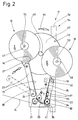
- the deflection roller 21 is mounted at a distance from the bobbin 16, on an (upright) supporting wall 22.
- the one from the bobbin 16 removed material web 14 is via a guide the deflection roller 21 supplied, namely via a Shoe 23.
- This is designed as an elongated, one-armed lever with a (lower) pivot bearing 24 adjacent to the deflection roller 21, above it.
- the shoe 23 has a guide surface 25 for the material web 14 provided.
- the shoe 23 is - seen in cross section - formed as an elongated hollow body with a corresponding Cross-sectional contour of the guide surface 25.
- As in particular 6 shows the shoe 23 in cross section approximately C-shaped, that is, open on one side Profile.
- the guide surface 25 forms obliquely at the edges Side strips 26, 27. These go to the free Outer edges over in angled guide leg 28, 29.
- the material web 14 runs continuously on that described in the Way contoured guide surface 25 along and thereby receives a corresponding, shaped cross-sectional shape.
- the material web 14 runs continuously on that described in the Way contoured guide surface 25 along and thereby receives a corresponding, shaped cross-sectional shape.
- the material web 14 in its longitudinal direction is deformed, i.e. in particular wrinkles.
- the shoe 23 due to the design of the guide surface 25 a holding force on the transported material web 14 it is possible with this device, the respective bobbin 16 to run completely empty, i.e. without disconnecting one Remaining part of the material web 14, which remains on the bobbin 16.
- a special feature lies in this and in the design of the shoe 23 the device.
- the shoe 23 is swiveled out the plane of movement of the material web 14 moved out into a Position shown in phantom in Fig. 2. After this Changing the bobbin, the shoe 23 is brought back into position, in which the material web 14 rests on the guide surface 25.
- the replacement bobbin 18 or its initial section 19 is adjacent to the deflection roller 21 for connection to the material web 14 kept ready.
- the initial section 19 lies on a transmission element on, namely on a transfer roller 30, which in turn at the lower or free end of a one-armed transmission lever 31 is stored.
- the latter is adjacent in the area of one pivot bearing 32 arranged for replacement bobbin 18 swiveling. This is also arranged on the common support wall 22.
- the relative position is chosen so that at a Pivoting movement according to arrow 33, the transfer roller 30 from the Starting position according to FIG. 2 in the transfer position Fig. 4 is pivoted. In this, the transfer roller 30 is immediate adjacent to the circumference of the deflection roller 21, namely such that a free end of the start section 19 to the material web 14 is pressed in the region of the deflecting roller 21.
- the replacement bobbin 18 is positioned so that the initial section 19 with the adhesive 15 of the transfer roller 30 and the Transmission lever 31 is turned.
- the initial section 19 is therefore with an adhesive surface on the circumference of the transfer roller 30 and - in the present embodiment - on Transmission lever 31 on.
- Transfer roller 30 and / or transfer lever 31 are designed that on the one hand the one with the adhesive side Material web is kept sufficient, but on the other hand Press on a side of the material web provided with adhesive 15 14 this detects the end of the beginning section 19 and of the transfer roller 30 or the transmission lever 31 deducts.
- the transfer roller 30 along the circumference Provide projections or increases. It is in the present case around protruding tips 34 which are here pyramid-shaped ridges 35 are formed. The increases 35 and thus their tips 34 are in the present case in longitudinal and transverse rows in regular distribution along the The circumference of the transfer roller 30 is arranged.
- the holding piece 36 is the same here Way as the transfer roller 30 with ridges 35 and 34 tips Mistake.
- the connection of the start section 19 of the new material web the running material web 14 is carried out automatically.
- the running bobbin 16 is driven completely empty.
- the end of the material web 14 is scanned.
- an expiring Lane 14 observing photocell 37 is provided.
- a rotating bearing of the bobbin 16 with a rotating one non-contact button, for example an initiator can in the area of a rotating bearing of the bobbin 16 with a rotating one non-contact button, for example an initiator, be formed, the standstill after the end of the material web 14 the bobbin holder or the reduced rotation speed as a signal for the complete removal of the material web 14 recognizes.
- the transmission lever 31 is described in the Senses swiveled up to the circumference of the deflection roller 21.
- the pivoting movement of the transmission lever 31 is caused by an actuator actuated by the photocell 37, namely by an (electric) cylinder 38, the piston rod 39 on a transverse arm 40 of the transmission lever 31 connected.
- the replacement bobbin 18 is in the present embodiment manually prepared for connection.
- the beginning section 19 is removed by hand from the replacement bobbin 18 and in the position described, bearing on the transfer roller 30 and transmission lever 31 brought.
- Below the transfer roller 30 there is a stationary knife 41 End of the initial section 19 separated, so that the initial section 19 always in an exact relative position Transfer roller 30 receives. It also has an exact end edge created by the knife 41.
- the knife 41 is also on the support wall 22 attached.
- the device or the splice station 17 is equipped with monitoring devices provided that the presence of material, namely the material web 14 monitored at the important areas.
- the rotational movement of the Deflection roller 21, on the one hand the presence of the material web 14 assumes.
- it can also be the correct one Deduction of the adhesive strips 10 are monitored, namely in terms of length.
- control disc 65 with (three) at equal circumferential distances from each other arranged radial projections 66 provided and on arranged a shaft for the deflection roller 21, that is, with this rotating.
- the initiator 64 is rotated by the protrusions 66 Control disc 65 applied. This will become basically recognizes the rotational movement of the deflection roller 21, on the other hand also the length of the stripped section the material web 14.
- the bobbins 16, 18 are adjustable, namely on a pivotable or rotatable member. It in the present case, this is an (upright) Support disc 42. This is rotatably supported by a central bearing 43, namely on the support wall 22. The support disc 42 is after each bobbin change rotated so that the replacement bobbin 18 reaches the position of the active bobbin 16. The support disk 42 is rotated clockwise according to arrow 44.
- the material web 14 comes from the area of the replacement bobbin 18 to rest on the shoe 23, the material web 14 with cross-sectional deformation in the cavity of the shoe 23 entry.
- the Shoe 23 pivotable about the (lower) pivot bearing 24 in the dash-dotted lines position shown in FIG. 2. In this position the rotation of the support disk 42 is carried out. Of the Shoe 23 is then pivoted back into the working position and takes up the material web 14.
- the support disk 42 is manual in this embodiment rotatable. Handles are provided for this purpose one handle 45, 46 each in the area of a reel bearing 47, 48. The transversely protruding handles 45, 46 can be grasped and so the Carrier disc 42 are rotated.
- the working position of the support plate 42 is fixed, namely by a locking pin, which can also be operated with handle 49 enters a locking hole 50 of the support plate 42 for fixation the same on a bracket, namely on the support wall 22nd
- the handles 45, 46 in the area of the reel bearings 47, 48 have a double function.
- the handles practice one by means of springs 51 axially directed pressure on the reels 16, 18 or on a Bobbin core 52 out. This creates a braking effect due to friction generated in the area of the reels 16, 18.
- the braking effect is adjustable with the help of knurled wheels 53, which are used for change the tension of the springs 51 can be adjusted.
- the device is overall on a portal-like Support frame 54 attached.
- the two on top of each other arranged splice stations 17 or their support wall 22 is on an upright support 55 of the support frame 54 is attached.
- On an opposite support 56 are the two tape units 12, 13 mounted on a bracket 57. This has one upper and lower transversely projecting support arm 58, 59.
- At the end a tape unit 12, 13 is mounted on each support arm.
- Each Tape aggregate 12, 13 is with a guide 60, 61 on the Support arm 58, 59 slidable, so that an exact position each Tape aggregates 12, 13 can be done in the horizontal direction.
- one of the tape aggregates 12, 13 is in the present Fall the top tape aggregate 12 in the vertical direction adjustable to adapt to different formats of the folding boxes 11.
- the support arm 58 has a vertical guide 62 connected. This is on an upright in the vertical direction Support rod 63 slidable. This is part of the bracket 57.
Landscapes
- Replacement Of Web Rolls (AREA)
Applications Claiming Priority (3)
| Application Number | Priority Date | Filing Date | Title |
|---|---|---|---|
| DE19731024 | 1997-07-18 | ||
| DE19731024A DE19731024A1 (de) | 1997-07-18 | 1997-07-18 | Verfahren und Vorrichtung zum Handhaben von klebstoffaufweisenden Bahnen |
| CN98116309A CN1083389C (zh) | 1997-07-18 | 1998-07-17 | 处理粘合带的装置 |
Publications (3)
| Publication Number | Publication Date |
|---|---|
| EP0893381A2 true EP0893381A2 (fr) | 1999-01-27 |
| EP0893381A3 EP0893381A3 (fr) | 1999-10-13 |
| EP0893381B1 EP0893381B1 (fr) | 2004-09-29 |
Family
ID=34827945
Family Applications (1)
| Application Number | Title | Priority Date | Filing Date |
|---|---|---|---|
| EP98112322A Expired - Lifetime EP0893381B1 (fr) | 1997-07-18 | 1998-07-03 | Procédé et dispositif pour manipuler des bandes comprenant de l'adhésif |
Country Status (7)
| Country | Link |
|---|---|
| US (1) | US6082661A (fr) |
| EP (1) | EP0893381B1 (fr) |
| JP (1) | JP4037531B2 (fr) |
| CN (1) | CN1083389C (fr) |
| BR (1) | BR9802496A (fr) |
| CA (1) | CA2243839C (fr) |
| DE (2) | DE19731024A1 (fr) |
Families Citing this family (10)
| Publication number | Priority date | Publication date | Assignee | Title |
|---|---|---|---|---|
| JP3568462B2 (ja) * | 2000-07-10 | 2004-09-22 | 日東電工株式会社 | 封緘装置 |
| DE50209291D1 (de) * | 2002-08-14 | 2007-03-08 | Hauni Maschinenbau Ag | Verfahren und Vorrichtung zum Verbinden von Materialbahnen |
| EP1389602B1 (fr) * | 2002-08-14 | 2006-08-09 | Hauni Maschinenbau AG | Méthode et dispositif pour raccorder des bandes de matériau |
| GB0304271D0 (en) * | 2003-02-25 | 2003-03-26 | Filtrona United Kingdom Ltd | Improvements in assembling packaging |
| DE102005033486A1 (de) * | 2005-07-19 | 2007-01-25 | Krones Ag | Vorrichtung und Verfahren zum Spleißen von Etikettenbändern |
| CN102642640A (zh) * | 2012-04-26 | 2012-08-22 | 南通通用机械制造有限公司 | 装箱机的自动封胶带机构 |
| DE102019203742A1 (de) * | 2019-02-07 | 2020-08-13 | Bhs Corrugated Maschinen- Und Anlagenbau Gmbh | Materialbahn-Einzugsvorrichtung |
| US11745970B1 (en) * | 2023-03-03 | 2023-09-05 | Elisa M. Duncan | Automatic sleeving splicer and methods of making and using the same |
| CN117142206B (zh) * | 2023-11-01 | 2024-01-23 | 江苏铨通印数字印刷有限公司 | 一种贴纸生产线自动续料设备 |
| US12384641B1 (en) | 2024-12-06 | 2025-08-12 | Elisa M. Duncan | Automatic sleeving splicer comprising moving upper and/or lower tape heads |
Family Cites Families (20)
| Publication number | Priority date | Publication date | Assignee | Title |
|---|---|---|---|---|
| DE1057912B (de) * | 1956-06-28 | 1959-05-21 | Minnesota Mining & Mfg | Vorrichtung zum Ankleben eines neuen Klebstreifens kurz vor Verbrauch eines ablaufenden Klebstreifens an dessen Ende |
| US2940506A (en) * | 1958-07-10 | 1960-06-14 | Akron Standard Mold Co | Material handling mechanism |
| US3201057A (en) * | 1963-08-01 | 1965-08-17 | Du Pont | Web unwind apparatus |
| GB1369078A (en) * | 1970-12-09 | 1974-10-02 | Matsushita Electric Industrial Co Ltd | Method and apparatus for automatically connecting tapes |
| US3880699A (en) * | 1973-09-07 | 1975-04-29 | Noritsu Koki Co Ltd | Automatic adhesive tape feeding device |
| US4039367A (en) * | 1975-12-31 | 1977-08-02 | The Loveshaw Corporation | Tape applying mechanisms of carton sealing machines |
| US4264401A (en) * | 1976-10-22 | 1981-04-28 | Ganz Brothers, Inc. | Web splicer |
| IT8320416U1 (it) * | 1983-01-07 | 1984-07-07 | Ims Spa | Dispositivo per il collegamento a registro e/o testa a testa delle estremità di due nastri di carta o cartone che si svolgono da due diverse bobine posizionate su un gruppo portabobine stellare a due o più posizioni |
| DE3439313C2 (de) * | 1984-10-26 | 1994-07-07 | Focke & Co | Vorrichtung zum Verbinden von Bahnen aus Verpackungsmaterial |
| JPS62180573A (ja) * | 1986-02-03 | 1987-08-07 | Fuji Photo Film Co Ltd | テ−プ欠陥除去方法 |
| DE3929981C1 (fr) * | 1989-09-08 | 1991-03-07 | Maschinenfabrik Alfred Schmermund Gmbh & Co, 5820 Gevelsberg, De | |
| DE3937286A1 (de) * | 1989-11-09 | 1991-05-16 | Hoechst Ag | Bandwechselvorrichtung |
| IT1239110B (it) * | 1990-03-06 | 1993-09-21 | Alfa Costr Mecc Spa | Perfezionamento in macchina etichettatrice per etichette autoadesive. |
| IT1245994B (it) * | 1991-02-26 | 1994-11-07 | Gd Spa | Metodo per l'alimentazione in continuo, ad una macchina utilizzatrice,di un nastro provvisto di tacche distribuite con passo costante. |
| IT227176Y1 (it) * | 1992-11-11 | 1997-09-15 | Ocme Srl | Dispositivo per la giunzione di film di materiale plastico termoestraibile in una macchina utilizzante detto film |
| DE69403657T2 (de) * | 1993-05-26 | 1998-01-22 | Minnesota Mining & Mfg | Klebeband-zuführungs-und anbringungssystem mit einem bahnverbindungsmechanismus |
| IT1269502B (it) * | 1994-02-03 | 1997-04-01 | Ims Spa | Metodo e macchina per svolgere e giuntare bobine di materiale in striscia |
| US5624526A (en) * | 1994-10-17 | 1997-04-29 | Minnesota Mining And Manufacturing | Continuous tape supply system including a tape splicing mechanism for use with box taping machines |
| FR2733972A1 (fr) * | 1995-05-11 | 1996-11-15 | Jean Jacques Chandellier | Nouveaux dispositifs pour ameliorer les performances d'une machine a coller les rubans adhesifs double face |
| FR2744695B3 (fr) * | 1996-02-10 | 1998-06-26 | Yeh Tsuang Hang | Mecanisme d'un dispositif d'application de ruban d'une machine de scellage de caisses pour eviter que ce ruban ne retombe |
-
1997
- 1997-07-18 DE DE19731024A patent/DE19731024A1/de not_active Withdrawn
-
1998
- 1998-07-03 DE DE59812016T patent/DE59812016D1/de not_active Expired - Lifetime
- 1998-07-03 EP EP98112322A patent/EP0893381B1/fr not_active Expired - Lifetime
- 1998-07-17 US US09/118,504 patent/US6082661A/en not_active Expired - Lifetime
- 1998-07-17 CA CA002243839A patent/CA2243839C/fr not_active Expired - Fee Related
- 1998-07-17 CN CN98116309A patent/CN1083389C/zh not_active Expired - Fee Related
- 1998-07-20 BR BR9802496A patent/BR9802496A/pt not_active IP Right Cessation
- 1998-07-21 JP JP20561198A patent/JP4037531B2/ja not_active Expired - Fee Related
Also Published As
| Publication number | Publication date |
|---|---|
| CA2243839A1 (fr) | 1999-01-18 |
| DE19731024A1 (de) | 1999-01-21 |
| CN1205971A (zh) | 1999-01-27 |
| US6082661A (en) | 2000-07-04 |
| EP0893381A3 (fr) | 1999-10-13 |
| CA2243839C (fr) | 2006-07-04 |
| BR9802496A (pt) | 1999-06-01 |
| JP4037531B2 (ja) | 2008-01-23 |
| EP0893381B1 (fr) | 2004-09-29 |
| JPH11116111A (ja) | 1999-04-27 |
| DE59812016D1 (de) | 2004-11-04 |
| CN1083389C (zh) | 2002-04-24 |
Similar Documents
| Publication | Publication Date | Title |
|---|---|---|
| DE3232162C2 (de) | Vorrichtung zum Aufbringen von Reifenmaterial | |
| DE3235437C2 (fr) | ||
| DE4020954B4 (de) | Ansetzband, insbesondere zum fliegenden Ansetzen von Papierbahnen | |
| DE2721883A1 (de) | Verfahren zur uebertragung einer papierbahn in einer papiermaschine sowie vorrichtung zur ausfuehrung des verfahrens | |
| DE3701146C2 (fr) | ||
| DE4107254C2 (de) | Vorrichtung zum Verbinden von Materialbahnen | |
| EP0442038A2 (fr) | Méthode et dispositif pour le remplacement automatique d'une bobine pleine par un nouveau noyau d'enroulement | |
| EP0500841B1 (fr) | Procede et dispositif de changement de rouleaux d'enroulement | |
| EP0881181B1 (fr) | Station de déroulage pour dérouler de façon continue une bande de matière | |
| DE2624802A1 (de) | Verfahren und vorrichtung zum stossverbinden von materialbahnen | |
| DE19546581C2 (de) | Vorrichtung zum Aufbringen von klebendem Montageband | |
| DE3816775A1 (de) | Verfahren und vorrichtung zur endauffuehrung einer bahn | |
| DE4325944A1 (de) | Verfahren und Vorrichtung zum Verbinden von Materialbahnen, insbesondere aus Verpackungsmaterial | |
| DE4115406A1 (de) | Wickelmaschine zum aufwickeln von materialbahnen | |
| EP0893381B1 (fr) | Procédé et dispositif pour manipuler des bandes comprenant de l'adhésif | |
| EP0453727B1 (fr) | Dispositif pour raccorder des bandes, en particulier des bandes de papier pour la production de carton ondulé | |
| DE3308059C2 (fr) | ||
| DE68916519T2 (de) | Vorrichtung zum Ausrichten von Bahnen. | |
| DE3914776C2 (de) | Verfahren und Vorrichtung zum Aufwickeln und Querschneiden einer laufenden Warenbahn | |
| DE102014211786A1 (de) | Halte- und Abrollvorrichtung für auf Rollen gewickeltes Flach- und/oder Folienmaterial, Behälterverpackungsanlage und Verfahren zum Wechseln einer Rolle mit Flach- und/oder Folienmaterial | |
| EP0464535B1 (fr) | Dispositif pour fixer un ruban adhésif au bout d'une bande et au tambour, qui est formé par la bande | |
| DE3440107C2 (fr) | ||
| DE102021104284B3 (de) | Vorrichtung zum Verbinden zweier Etikettenbänder sowie Spleißanordnung, umfassend eine derartige Vorrichtung | |
| EP0994055A2 (fr) | Dispositif pour le transfert d'un matériaux de liaison double face | |
| DE4220792C2 (de) | Klebevorrichtung |
Legal Events
| Date | Code | Title | Description |
|---|---|---|---|
| PUAI | Public reference made under article 153(3) epc to a published international application that has entered the european phase |
Free format text: ORIGINAL CODE: 0009012 |
|
| AK | Designated contracting states |
Kind code of ref document: A2 Designated state(s): AT BE CH CY DE DK ES FI FR GB GR IE IT LI LU MC NL PT SE |
|
| AX | Request for extension of the european patent |
Free format text: AL;LT;LV;MK;RO;SI |
|
| PUAL | Search report despatched |
Free format text: ORIGINAL CODE: 0009013 |
|
| AK | Designated contracting states |
Kind code of ref document: A3 Designated state(s): AT BE CH CY DE DK ES FI FR GB GR IE IT LI LU MC NL PT SE |
|
| AX | Request for extension of the european patent |
Free format text: AL;LT;LV;MK;RO;SI |
|
| 17P | Request for examination filed |
Effective date: 20000411 |
|
| AKX | Designation fees paid |
Free format text: AT BE CH CY DE DK ES FI FR GB GR IE IT LI LU MC NL PT SE |
|
| AXX | Extension fees paid |
Free format text: AL;LT;LV;MK;RO;SI |
|
| 17Q | First examination report despatched |
Effective date: 20000712 |
|
| GRAP | Despatch of communication of intention to grant a patent |
Free format text: ORIGINAL CODE: EPIDOSNIGR1 |
|
| GRAS | Grant fee paid |
Free format text: ORIGINAL CODE: EPIDOSNIGR3 |
|
| GRAA | (expected) grant |
Free format text: ORIGINAL CODE: 0009210 |
|
| AK | Designated contracting states |
Kind code of ref document: B1 Designated state(s): CH DE FR GB IT LI NL |
|
| REG | Reference to a national code |
Ref country code: GB Ref legal event code: FG4D Free format text: NOT ENGLISH |
|
| REG | Reference to a national code |
Ref country code: CH Ref legal event code: EP |
|
| REF | Corresponds to: |
Ref document number: 59812016 Country of ref document: DE Date of ref document: 20041104 Kind code of ref document: P |
|
| RAP2 | Party data changed (patent owner data changed or rights of a patent transferred) |
Owner name: FOCKE & CO. (GMBH & CO. KG) |
|
| REG | Reference to a national code |
Ref country code: CH Ref legal event code: NV Representative=s name: R. A. EGLI & CO. PATENTANWAELTE |
|
| GBT | Gb: translation of ep patent filed (gb section 77(6)(a)/1977) |
Effective date: 20041125 |
|
| NLT2 | Nl: modifications (of names), taken from the european patent patent bulletin |
Owner name: FOCKE & CO. (GMBH & CO. KG) |
|
| PLBE | No opposition filed within time limit |
Free format text: ORIGINAL CODE: 0009261 |
|
| STAA | Information on the status of an ep patent application or granted ep patent |
Free format text: STATUS: NO OPPOSITION FILED WITHIN TIME LIMIT |
|
| ET | Fr: translation filed | ||
| 26N | No opposition filed |
Effective date: 20050630 |
|
| PGFP | Annual fee paid to national office [announced via postgrant information from national office to epo] |
Ref country code: CH Payment date: 20130712 Year of fee payment: 16 |
|
| PGFP | Annual fee paid to national office [announced via postgrant information from national office to epo] |
Ref country code: GB Payment date: 20130703 Year of fee payment: 16 |
|
| PGFP | Annual fee paid to national office [announced via postgrant information from national office to epo] |
Ref country code: DE Payment date: 20140730 Year of fee payment: 17 Ref country code: NL Payment date: 20140710 Year of fee payment: 17 |
|
| PGFP | Annual fee paid to national office [announced via postgrant information from national office to epo] |
Ref country code: FR Payment date: 20140708 Year of fee payment: 17 |
|
| PGFP | Annual fee paid to national office [announced via postgrant information from national office to epo] |
Ref country code: IT Payment date: 20140717 Year of fee payment: 17 |
|
| REG | Reference to a national code |
Ref country code: CH Ref legal event code: PL |
|
| GBPC | Gb: european patent ceased through non-payment of renewal fee |
Effective date: 20140703 |
|
| PG25 | Lapsed in a contracting state [announced via postgrant information from national office to epo] |
Ref country code: CH Free format text: LAPSE BECAUSE OF NON-PAYMENT OF DUE FEES Effective date: 20140731 Ref country code: LI Free format text: LAPSE BECAUSE OF NON-PAYMENT OF DUE FEES Effective date: 20140731 |
|
| PG25 | Lapsed in a contracting state [announced via postgrant information from national office to epo] |
Ref country code: GB Free format text: LAPSE BECAUSE OF NON-PAYMENT OF DUE FEES Effective date: 20140703 |
|
| REG | Reference to a national code |
Ref country code: DE Ref legal event code: R119 Ref document number: 59812016 Country of ref document: DE |
|
| REG | Reference to a national code |
Ref country code: NL Ref legal event code: MM Effective date: 20150801 |
|
| PG25 | Lapsed in a contracting state [announced via postgrant information from national office to epo] |
Ref country code: DE Free format text: LAPSE BECAUSE OF NON-PAYMENT OF DUE FEES Effective date: 20160202 Ref country code: IT Free format text: LAPSE BECAUSE OF NON-PAYMENT OF DUE FEES Effective date: 20150703 |
|
| REG | Reference to a national code |
Ref country code: FR Ref legal event code: ST Effective date: 20160331 |
|
| PG25 | Lapsed in a contracting state [announced via postgrant information from national office to epo] |
Ref country code: NL Free format text: LAPSE BECAUSE OF NON-PAYMENT OF DUE FEES Effective date: 20150801 Ref country code: FR Free format text: LAPSE BECAUSE OF NON-PAYMENT OF DUE FEES Effective date: 20150731 |