EP0893625B1 - Couple d'engrenages pour entrainer un cylindre d'impression avec dispositif de restauration de la phase - Google Patents
Couple d'engrenages pour entrainer un cylindre d'impression avec dispositif de restauration de la phase Download PDFInfo
- Publication number
- EP0893625B1 EP0893625B1 EP98113702A EP98113702A EP0893625B1 EP 0893625 B1 EP0893625 B1 EP 0893625B1 EP 98113702 A EP98113702 A EP 98113702A EP 98113702 A EP98113702 A EP 98113702A EP 0893625 B1 EP0893625 B1 EP 0893625B1
- Authority
- EP
- European Patent Office
- Prior art keywords
- gear wheels
- gear
- axial
- printing drum
- couple
- Prior art date
- Legal status (The legal status is an assumption and is not a legal conclusion. Google has not performed a legal analysis and makes no representation as to the accuracy of the status listed.)
- Expired - Lifetime
Links
Images



Classifications
-
- F—MECHANICAL ENGINEERING; LIGHTING; HEATING; WEAPONS; BLASTING
- F16—ENGINEERING ELEMENTS AND UNITS; GENERAL MEASURES FOR PRODUCING AND MAINTAINING EFFECTIVE FUNCTIONING OF MACHINES OR INSTALLATIONS; THERMAL INSULATION IN GENERAL
- F16H—GEARING
- F16H55/00—Elements with teeth or friction surfaces for conveying motion; Worms, pulleys or sheaves for gearing mechanisms
- F16H55/02—Toothed members; Worms
- F16H55/17—Toothed wheels
- F16H55/18—Special devices for taking up backlash
-
- B—PERFORMING OPERATIONS; TRANSPORTING
- B41—PRINTING; LINING MACHINES; TYPEWRITERS; STAMPS
- B41F—PRINTING MACHINES OR PRESSES
- B41F13/00—Common details of rotary presses or machines
- B41F13/008—Mechanical features of drives, e.g. gears, clutches
- B41F13/012—Taking-up backlash
-
- Y—GENERAL TAGGING OF NEW TECHNOLOGICAL DEVELOPMENTS; GENERAL TAGGING OF CROSS-SECTIONAL TECHNOLOGIES SPANNING OVER SEVERAL SECTIONS OF THE IPC; TECHNICAL SUBJECTS COVERED BY FORMER USPC CROSS-REFERENCE ART COLLECTIONS [XRACs] AND DIGESTS
- Y10—TECHNICAL SUBJECTS COVERED BY FORMER USPC
- Y10T—TECHNICAL SUBJECTS COVERED BY FORMER US CLASSIFICATION
- Y10T74/00—Machine element or mechanism
- Y10T74/19—Gearing
- Y10T74/19623—Backlash take-up
-
- Y—GENERAL TAGGING OF NEW TECHNOLOGICAL DEVELOPMENTS; GENERAL TAGGING OF CROSS-SECTIONAL TECHNOLOGIES SPANNING OVER SEVERAL SECTIONS OF THE IPC; TECHNICAL SUBJECTS COVERED BY FORMER USPC CROSS-REFERENCE ART COLLECTIONS [XRACs] AND DIGESTS
- Y10—TECHNICAL SUBJECTS COVERED BY FORMER USPC
- Y10T—TECHNICAL SUBJECTS COVERED BY FORMER US CLASSIFICATION
- Y10T74/00—Machine element or mechanism
- Y10T74/19—Gearing
- Y10T74/1987—Rotary bodies
- Y10T74/19893—Sectional
- Y10T74/19898—Backlash take-up
Definitions
- the present invention relates to a couple of gear wheels able to drive a printing drum according to the preamble of claim 1.
- JP-A-59-12893 there is shown a drum unit of a rotary stencil printer, comprising a frame which supports a cylindrical printing drum having a perforated circumferential portion to be rotatable about its central axis, together with ink supply means for supplying ink to the printing drum from its inside, a receiver for an ink container for supplying ink, and an ink pump, while the frame is supported and guided relative to a machine body of the printer by support and guide means, to be movable along the central axis of the drum, so that the printing drum is movable between the printing position inside the machine body and a draw-out position outside the machine body.
- a shaft member on the printing drum projecting from an end wall of the printing drum coaxially to the central axis thereof coaxially engages into a mating hole of a drive shaft provided on the machine body, so that the printing drum is driven by a drive source provided in the machine body.
- a stencil leading end mounting device for clamping a leading edge of a stencil sheet to the printing drum along a generatrix thereof is provided in the printing drum so as to project radially outward from a cylindrical outer circumference of the printing drum, and in this connection, such an operation is required that a back press roller for pressing a print sheet against the rotating printing drum for applying a printing on the print sheet is retracted away from the printing drum when the stencil sheet leading end mounting device traverses in front of the back press roller, to avoid a collision of the stencil sheet leading end mounting device with the back press roller.
- the above-mentioned reference JP-08-039918 shows two gear wheels having each one disk at a plane surface thereof. These disks prevent a relative axial displacement between the gears so that it is prevented that the gear wheels can axially get into and out of the meshing engagement for allowing a drum to move into and out of the operating position.
- EP-0 748 955 which is equivalent to the above-mentioned document JP-8338500, describes a gear sector for suppressing backlash reversal between two gear wheels.
- the gear sector is adjusted relative to the one gear wheel so that a backlash between the gears is reduced.
- a highly stabilized uniform torque transmission is available for driving the printing drum via an axially engageable and disengageable meshing of a couple of gear wheels each having a duplicate gear construction capable of suppressing a backlash in the gear meshing therebetween, while ensuring that, when the printing drum drawn out of the printing position inside the machine body for the purpose of inspection, maintenance, color change, etc. is remounted to the printing position, the rotational relationship between the printing drum and the printing drum driving system in the machine body is always set at a predetermined condition.
- Fig. 1 showing essential portions of a first embodiment. of a couple of gear wheels for driving a printing drum
- 10 is a printing drum. at an end of which is coaxially mounted a first gear wheel 12 on the printing drum.
- 14 is a second gear wheel on the machine body not shown in the figure.
- the gear wheel 14 is rotatably mounted by a shaft 16 extended from a supporting part of the machine body of a stencil printer, the supporting part of the machine body being positioned on the side of the gear wheel 14 closer to the viewer as viewed in the figure.
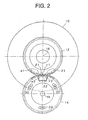
- the printing drum 10 is movable by a frame and a support and guide means not shown in the figure along the central axis 18 of the printing drum between a printing position inside the machine body and a drawn out position outside the machine body. so that, when the printing drum is set at the printing position, the gear wheel 12 is laid over the gear wheel 14 along the thickness thereof, as shown in Fig. 2 when viewed in the direction of the central axes of the gear wheels.
- the gear wheel 12 has a first axial portion 12a bearing a spur gear 12aa on the side closer to the printing drum and a second axial portion 12b bearing a spur gear 12bb on the side closer to the part of the machine body supporting the gear wheel 14.
- the gear wheel 14 on the machine body has a first axial portion 14a bearing a spur gear 14aa on the side closer to the printing drum and a second axial portion 14b bearing a spur gear 14bb on the side closer to the supporting part of the machine body.
- the gear wheels 12 and 14 are of a same diameter as one another, or more precisely, the pitch circle of the spur gear 12aa and the pitch circle of the spur gear 14aa are of a common diameter, while the pitch circle of the spur gear 12bb and the pitch circle of the spur gear 14bb are of a common diameter.
- the spur gear 12aa and the spur gear 12bb are of a common diameter, although there is a difference in the rotational phase of the two gears corresponding to a half of the pitch angle of the gear teeth.
- the spur gear 14aa and the spur gear 14bb are of a common diameter, although there is a difference in the rotational phase of the two gears corresponding to a half of the pitch angle of the gear teeth.
- these conditions are met with respect to the gear teeth excluding several gear teeth position in the meshing area when the gear wheels 12 and 14 are meshing at a predetermined rotational relationship relative to one another with the printing drum 10 being positioned at a corresponding predetermined rotational position.
- the gear teeth in the above-mentioned meshing area corresponding to the predetermined relative rotational position of the gear wheels are formed to satisfy a special condition.
- two gear wheels 12 and 14 are of a common diameter, one of them may have a diameter which is integer times as that of the other, so that the gear train is an acceleration of deceleration gear train.
- the spur gear 12bb of the gear wheel 12 is modified to align with the spur gear 12aa.
- the part of the spur gear 12bb at which the tooth shape is modified is shown by teeth ⁇ 1, ⁇ 1, ⁇ 1 and ⁇ 1.
- gear wheel 14 some teeth of the spur gear 14bb in the above-mentioned predetermined meshing area are modified in the tooth shape, so as to align with the spur gear 14aa, as designated by ⁇ 2, ⁇ 2 and ⁇ 2.
- the gear teeth ⁇ 2, ⁇ 2 and ⁇ 2 are aligned with the gear 14aa as formed integral therewith.
- the gear teeth ⁇ 1, ⁇ 2, ⁇ 1 and ⁇ 1 of the gear wheel 12 are also aligned with the gear 12aa as formed integral therewith and continuous over the first and second axial portions.
- the second axial portion 14b of the gear wheel 14 is constructed by a disk member separate from the first axial portion 14a, the disk member being formed with a notch at a portion thereof and fastened to the first axial portion 14a by three bolts 22 passed through three arcuately elongated openings 20 formed in the disk member, so that a fine adjustment of the angular phase position of the gear 14bb relative to the gear 14aa is available. except the gear teeth ⁇ 2, ⁇ 2 and ⁇ 2.
- gear wheels 12 and 14 when the gear wheels 12 and 14 are in the predetermined relative rotational position shown in the figure, these gear wheels are axially movable relative to one another between an engaged position in which the first axial portion 12a of the gear wheel 12 lies axially over the first axial portion 14a of the gear wheel 14 so as to mesh therewith, while the second axial portion 12b of the gear wheel 12 lies axially over the second axial portion 14b of the gear wheel 14 so as to mesh therewith, and a disengaged position in which the two gear wheels are axially apart from one another.
- the printing drum when the printing drum is drawn out from the printing position toward outside the machine body, it is ensured that the printing drum and the printing drum drive system on the machine body are definitely set at the predetermined relative rotational position, while when the printing drum is remounted to the printing position in the machine body, it is ensured that the printing drum and the printing drum driving system are engaged to establish a correct rotational relationship.
- Figs. 1 and 2 may be modified such that the spur gears 12aa and 14aa and the spur gears 12bb and 14bb meshing with one another are helical gears instead of being spur gears.
- the spur gears 12aa and 14aa and the spur gears 12bb and 14bb meshing with one another are helical gears instead of being spur gears.
- Fig. 3 is a view similar to Fig. 1, showing a second embodiment of the couple of gear wheels for driving a printing drum according to the present invention.
- Fig. 3 the portions corresponding to those shown in Fig. 1 are designated by the same reference numerals.
- a portion of the spur gear 14'b of the gear wheel 14' corresponding to the gear teeth ⁇ 2, ⁇ 2 and ⁇ 2 of the spur gear 14b of the gear wheel is removed.
- Such a construction has an advantage that, when the second axial portion 14'b of the gear wheel 14' is constructed as a disk member separate from the first axial portion 14'a, the manufacture of the gear wheel is easier. in other words, the first axial portion 14'a of the gear wheel 14' need not be made to have a larger thickness at the portion providing the gear teeth ⁇ 2, ⁇ 2 and ⁇ 2 as in the first embodiment shown in Fig. 1, so that the first axial portion 14'a and the second axial portion 14'b may each be made from a disk member of a constant thickness.
- each of the first axial portions 12a and 14a is made larger than that of each of the second axial portions 12b and 14b or 14'b in the gear wheels 12 and 14 or 14'. respectively, so that the spur gears 12aa and 14aa provide a primary rotational power transmitting means, while the spur gears 12bb and 14bb or 14'bb provide a backlash suppressing means.
- the positional relationship between the primary rotational power transmitting means and the backlash suppressing means in the gear wheels 12 and 14 or 14' may be reversed to be opposite to that of the embodiments shown in Figs.
- the gear shape may be such that, when the gear wheels 12 and 14 or 14' are at the predetermined rotational relationship relative to one another, the spur gears 12aa and 14aa align with the spur gears 12bb and 14bb or 14'bb, respectively. Further, in such a modification, at the portion of the gear wheel 12 where the spur gear 12aa is to align with the spur gear 12bb, a pertinent portion of the spur gear 12aa may be removed.
- the printing drum 10 can be drawn out of the machine body from the printing position or restored from outside the machine body to the printing position inside the machine body only when the gear wheels 12 and 14 or 14' are both set at the predetermined relative rotational position.
- Fig. 4 is a diagrammatical side view of a couple of gear wheels for driving a printing drum according to the present invention, in which the axial length of each of the first axial portions 12a and 14a are larger than that of each of the second axial portions 12b and 14b in the gear wheels 12 and 14, respectively, as in the first embodiment shown in Figs. 1 and 2, illustrating when it is signaled in the process of mounting the printing drum from outside the machine body to the printing position inside the machine body that the rotational position of the printing drum is not at the predetermined rotational position, regardless whether the rotational position of the gear wheel on the machine body is at the predetermined rotational position or not.
- the gear wheel 12 can be shifted relative to the gear wheel 14 so far as to leave the second axial portion 14b as shown in Fig. 5, where a further shifting of the printing drum is obstructed.
- the incorrectness of the rotational position of the printing drum driving system in the machine body for receiving the printing drum is signaled when the printing drum has been shifted toward its final mounting position so far as to leave a relatively small depth D2.
- the axial length of the first axial portion being different from that of the second axial portion, when the printing drum can not be mounted to its final mounting position, it can be judged according to whether the depth of shifting of the printing drum left as obstructed is relatively large or small, which of the printing drum and the printing drum driving system in the machine body is not correctly set at the predetermined rotational position, so that the matter is more swiftly attended to.
- the printing drum when the printing drum is not correctly set at the predetermined rotational position, it is signaled by the gear wheel 12 being obstructed from a further shifting in meshing with the gear wheel 14, leaving a relatively small depth D2 corresponding to the axial length of the first axial portion 12a. Therefore, also in this case, it is clearly judged according to whether the depth of shifting left as obstructed in the insertion of the printing drum into the machine body is relatively large or small.
Landscapes
- Engineering & Computer Science (AREA)
- Mechanical Engineering (AREA)
- General Engineering & Computer Science (AREA)
- Gear Transmission (AREA)
- Rotary Presses (AREA)
Claims (11)
- Paire de roues d'engrenage capable d'entraíner un cylindre d'impression (10) d'une machine à imprimer ayant un corps de machine, comprenant :lesdites première et seconde roues d'engrenage étant adaptées ;une première roue d'engrenage (12) montée sur le cylindre d'impression, etune seconde roue d'engrenage (14, 14') supportée en rotation par une pièce du corps de la machine,lesdites première et seconde roues d'engrenage ayant soit le même diamètre l'une par rapport à l'autre, soit l'une étant un nombre entier de fois plus grande que l'autre, caractérisée par :pour se mettre en prise l'une par rapport à l'autre lorsque le cylindre d'impression (10) est réglé à une position d'impression située à l'intérieur du corps de la machine de sorte à entraíner le cylindre d'impression (10) par une source d'entraínement prévue dans le corps de la machine via la mise en prise d'engrenage entre les première et seconde roues d'engrenage, etpour supprimer la mise en prise d'engrenage lorsque la première roue d'engrenage est déplacée de façon axiale avec le cylindre d'impression (10) vers l'extérieur du corps de la machine,dans laquelle les secondes parties axiales (12b, 14b, 14'b) des première et seconde roues d'engrenage (12 et 14, 14') ont chacune une forme de dent alignée de façon axiale avec celle de la première partie axiale correspondante (12a, 14a) et un manque de dents exceptionnellement à la partie circonférentielle particulière de celle-ci, de sorte que les première et seconde roues d'engrenage peuvent se déplacer de façon axiale dans et à l'extérieur de la mise en prise pour permettre au cylindre d'impression (10) de se déplacer dans et hors de la position d'impression uniquement lorsque la paire de roues d'engrenage se trouvent dans la mise en prise d'engrenage avec les secondes parties axiales respectives (12b, 14b, 14'b) de celles-ci alignées avec une autre au niveau des parties circonférentielles particulières.lesdites première et seconde roues d'engrenage (12 et 14, 14') ayant chacune des premières et secondes parties axiales (12a, 14a et 12b, 14b, 14'b),lesdites premières parties axiales (12a, 14a) étant plus proches du cylindre d'impression (10) que les secondes parties axiales (12b, 14b, 14'b), tandis quelesdites secondes parties axiales (12b, 14b, 14'b) étant plus proches de la pièce du corps de la machine que lesdites premières parties axiales (12a, 14a),lesdites premières et secondes parties axiales (12a, 14a, et 12b, 14b, 14'b) étant chacune formée soit par un engrenage cylindrique ou un engrenage à denture hélicoïdale avec un changement de phase entre les premières et les secondes parties axiales de chacune des première et seconde roues d'engrenage,lesdites première et seconde roues d'engrenage (12 et 14, 14') ayant chacune une partie circonférentielle particulière qui doit se trouver dans une mise en prise d'engrenage entre elles lorsque les première et seconde roues d'engrenage se trouvent dans une relation de rotation prédéterminée l'une par rapport à l'autre,
- Paire de roues d'engrenage selon la revendication 1, dans laquelle la forme de dent des premières et secondes parties axiales (12a, 14a ; 14'a, 12b, 14b ; 14'b) d'au moins une des première et seconde roues d'engrenage (12, 14 ; 14') est mise en prise selon les dents de la première partie axiale au niveau de la partie circonférentielle particulière.
- Paire de roues d'engrenage selon la revendication 1, dans laquelle la forme de dent des premières et secondes parties axiales (12a, 14a ; 14'a, 12b, 14b; 14'b) d'au moins une des première et seconde roues d'engrenage (12, 14 ; 14') est mise en prise selon les dents de la seconde partie axiale (12b, 14b ; 14'b) au niveau de la partie circonférentielle particulière.
- Paire de roues d'engrenage selon la revendication 1, dans laquelle les dents de la seconde partie axiale (14b ; 14'b) de la seconde roue d'engrenage (14 ; 14') sont sensiblement retirées au niveau de la partie circonférentielle particulière.
- Paire de roues d'engrenage selon la revendication 1, dans laquelle les dents de la première partie axiale de la première roue d'engrenage (12) sont sensiblement retirées au niveau de la partie circonférentielle particulière.
- Paire de roues d'engrenage selon la revendication 1, dans laquelle les premières parties axiales (12a, 14a ; 14'a) de chacune des première et seconde roues d'engrenage (12, 14 ; 14') ont une longueur axiale plus grande que les secondes parties axiales (12b, 14b ; 14'b) de celle-ci.
- Paire de roues d'engrenage selon la revendication 3, dans laquelle la seconde partie axiale (12b, 14b ; 14'b) de chacune des première et seconde roues d'engrenage (12, 14 ; 14') a une longueur axiale plus grande que la première partie axiale (12a, 14a ; 14'a) de celle-ci.
- Paire de roues d'engrenage selon la revendication 6, dans laquelle les première et seconde roues d'engrenage (12, 14 ; 14') laissent une quantité de jeu entre les dents dans la mise en prise d'engrenage au niveau des premières parties axiales (12a, 14a ; 14'a) de celles-ci, tandis que les dents (α2, β2, γ2) de la seconde partie axiale (14b ; 14'b) de la seconde roue d'engrenage (14 ; 14') sont plus déplacées par rapport aux dents de la première partie axiale (14a ; 14'a) de la seconde roue d'engrenage (14 ; 14') que le déplacement des dents (α1, β1, γ1) de la seconde partie axiale (12b) de la première roue d'engrenage (12) par rapport aux dents de la première partie axiale (12a) de la première roue d'engrenage (12) par un déplacement supplémentaire correspondant à la quantité de jeu entre les dents de sorte que la mise en prise d'engrenage située entre les première et seconde roues d'engrenage (12, 14 ; 14') au niveau des secondes parties axiales (12b, 14b ; 14'b) supprime le jeu entre les dents dans la mise en prise d'engrenage située entre les première et seconde roues d'engrenage (12, 14 ; 14') au niveau des premières parties axiales (12a, 14a ; 14'a).
- Paire de roues d'engrenage selon la revendication 7, dans laquelle les première et seconde roues d'engrenage (12, 14 ; 14') laissent une quantité de jeu entre les dents dans la mise en prise d'engrenage au niveau des secondes parties axiales (12b, 14b ; 14'b) de celles-ci, tandis que les dents de la première partie axiale (14a ; 14'a) de la seconde roue d'engrenage (14 ; 14') sont plus déplacées par rapport aux dents (α2, β2, γ2) de la seconde partie axiale (14b; 14'b) de la seconde roue d'engrenage (14 ; 14') que le déplacement des dents de la première partie axiale (12a) de la première roue d'engrenage (12) par rapport aux dents (α1, β1, γ1) de la seconde partie axiale (12b) de la première roue d'engrenage (12) par un déplacement supplémentaire correspondant à la quantité de jeu entre les dents de sorte que la mise en prise d'engrenage située entre les première et seconde roues d'engrenage (12, 14 ; 14') au niveau des premières parties axiales (12a, 14a ; 14'a) de celles-ci supprime le jeu entre les dents dans la mise en prise d'engrenage située entre les première et seconde roues d'engrenage (12, 14 ; 14') au niveau des secondes parties axiales (12b, 14b ; 14'b) de celles-ci.
- Paire de roues d'engrenage selon la revendication 1, comprenant en outre un mécanisme de réglage pour régler une position de rotation d'une première pièce d'au moins l'une des premières et secondes parties axiales (12a, 14a ; 14'a, 12b, 14b ; 14'b) d'au moins l'une des première et seconde roues d'engrenage (12, 14 ; 14') par rapport à l'autre des premières et secondes parties axiales (12a, 14a ; 14'a, 12b, 14b ; 14'b) pour un réglage fin, la première pièce excluant une seconde pièce de celle-ci correspondant à la partie circonférentielle particulière.
- Paire de roues d'engrenage selon la revendication 1, dans laquelle le manque de dents au niveau de la partie circonférentielle particulière ne représente que la seconde partie axiale (14b ; 14'b) de la seconde roue d'engrenage (14 ; 14').
Applications Claiming Priority (3)
| Application Number | Priority Date | Filing Date | Title |
|---|---|---|---|
| JP21265097 | 1997-07-23 | ||
| JP212650/97 | 1997-07-23 | ||
| JP9212650A JPH1134466A (ja) | 1997-07-23 | 1997-07-23 | 版胴駆動用係脱式歯車装置 |
Publications (3)
| Publication Number | Publication Date |
|---|---|
| EP0893625A2 EP0893625A2 (fr) | 1999-01-27 |
| EP0893625A3 EP0893625A3 (fr) | 1999-09-29 |
| EP0893625B1 true EP0893625B1 (fr) | 2003-03-12 |
Family
ID=16626149
Family Applications (1)
| Application Number | Title | Priority Date | Filing Date |
|---|---|---|---|
| EP98113702A Expired - Lifetime EP0893625B1 (fr) | 1997-07-23 | 1998-07-22 | Couple d'engrenages pour entrainer un cylindre d'impression avec dispositif de restauration de la phase |
Country Status (4)
| Country | Link |
|---|---|
| US (1) | US5964150A (fr) |
| EP (1) | EP0893625B1 (fr) |
| JP (1) | JPH1134466A (fr) |
| DE (1) | DE69812004D1 (fr) |
Families Citing this family (17)
| Publication number | Priority date | Publication date | Assignee | Title |
|---|---|---|---|---|
| DE19928960A1 (de) * | 1999-06-24 | 2000-12-28 | Volkswagen Ag | Zahnradtrieb |
| DE19953664A1 (de) * | 1999-11-08 | 2001-05-10 | Heidelberger Druckmasch Ag | Vorrichtung zur Sicherung eines korrekten Zahneingriffes beim Einkoppeln zweier Zahnräder |
| IT250014Y1 (it) * | 2000-07-03 | 2003-07-07 | Re M S R L | Struttura di ruota dentata |
| US6622582B1 (en) | 2000-07-14 | 2003-09-23 | Lexmark International, Inc. | Assembly for limiting axial motion of shaft in an imaging apparatus |
| DE10157500B4 (de) * | 2000-12-19 | 2015-06-18 | Heidelberger Druckmaschinen Ag | Rotationsdruckmaschine |
| JP4081662B2 (ja) * | 2001-12-14 | 2008-04-30 | 富士ゼロックス株式会社 | 駆動装置及びこれを用いた画像形成装置 |
| EP1371487A1 (fr) * | 2002-06-12 | 2003-12-17 | Müller Martini Holding AG | Dispositif pour le traitement d'une bande |
| US20040089089A1 (en) * | 2002-11-08 | 2004-05-13 | Stevens Carlos J. | Anti-backlash method and system for multiple mesh gear train |
| JP4470163B2 (ja) * | 2003-09-03 | 2010-06-02 | 株式会社エンプラス | 成形プラスチック歯車及びこれを使用した間歇回転伝達機構、成形プラスチック歯車の使用方法 |
| JP4375723B2 (ja) * | 2004-02-24 | 2009-12-02 | 株式会社エンプラス | 歯車 |
| USD527738S1 (en) * | 2004-03-31 | 2006-09-05 | Pearson Sr David Kent | Set of components for a vernier adjustable gear having an unequal number of holes in adjoining parts |
| JP4640777B2 (ja) * | 2005-01-31 | 2011-03-02 | 株式会社エンプラス | 樹脂製歯車装置 |
| TWI370316B (en) * | 2007-07-27 | 2012-08-11 | Aixin Technologies Llc | Illumination system |
| NL2007083C2 (en) * | 2011-07-11 | 2013-01-14 | Vcst Ind Products Bvba | Gear train comprising a scissor gear and a split gear. |
| TWI452218B (zh) * | 2012-02-07 | 2014-09-11 | Nat Univ Chung Cheng | No backlash gear structure |
| DE102017126205A1 (de) * | 2017-11-09 | 2019-05-09 | Man Truck & Bus Ag | Zahnrad, insbesondere Zwischenrad, für einen Rädertrieb |
| GB201913978D0 (en) * | 2019-09-27 | 2019-11-13 | Ocado Innovation Ltd | A cogwheel |
Family Cites Families (14)
| Publication number | Priority date | Publication date | Assignee | Title |
|---|---|---|---|---|
| DE516885C (de) * | 1931-01-28 | Albert Schnellpressen | Zahnradantrieb des Druck- und Formzylinders bei Rotationsdruckmaschinen | |
| US3359819A (en) * | 1966-04-25 | 1967-12-26 | Leo J Veillette | Bidirectional step torque filter with zero backlash characteristic |
| CA1029240A (fr) * | 1973-08-01 | 1978-04-11 | Harris Corporation | Commande de presse d'imprimerie |
| US3974710A (en) * | 1975-06-02 | 1976-08-17 | Granger Wallace H | Gear drive for rotary press and the like |
| JPS5912893A (ja) * | 1982-07-13 | 1984-01-23 | Riso Kagaku Corp | 孔版印刷用版胴装置 |
| JPS5912839A (ja) | 1982-07-13 | 1984-01-23 | ダウ化工株式会社 | 低温用複合板断熱構造物 |
| DE3626452A1 (de) * | 1986-08-05 | 1988-02-18 | Koenig & Bauer Ag | Einrichtung zur beseitigung des spiels der zaehne von antriebszahnraedern eines zahnradgetriebes in einer bogenrotationsdruckmaschine |
| US4781073A (en) * | 1987-06-24 | 1988-11-01 | The United States Of America As Represented By The Secretary Of The Army | Adjustable antibacklash gear system |
| US5181433A (en) * | 1990-09-20 | 1993-01-26 | Chiba Dies Co., Ltd. | Gear |
| DE4435011C2 (de) * | 1994-09-30 | 1997-04-30 | Roland Man Druckmasch | Verfahren zur Antriebsspielbeseitigung im Antrieb einer Bogendruckmaschine und Vorrichtung zu seiner Durchführung |
| DE19616503C2 (de) * | 1995-05-10 | 2003-08-28 | Volkswagen Ag | Getriebezahnrad mit magnetischer Zahnscheibe |
| JP3526974B2 (ja) * | 1995-06-13 | 2004-05-17 | 理想科学工業株式会社 | バックラッシュ反転抑制手段を有するカム装置 |
| JP2625406B2 (ja) * | 1995-07-21 | 1997-07-02 | 株式会社リコー | 印刷機の版胴駆動装置 |
| JP3650226B2 (ja) * | 1996-08-13 | 2005-05-18 | 株式会社小森コーポレーション | 印刷機 |
-
1997
- 1997-07-23 JP JP9212650A patent/JPH1134466A/ja active Pending
-
1998
- 1998-07-16 US US09/116,466 patent/US5964150A/en not_active Expired - Fee Related
- 1998-07-22 DE DE69812004T patent/DE69812004D1/de not_active Expired - Lifetime
- 1998-07-22 EP EP98113702A patent/EP0893625B1/fr not_active Expired - Lifetime
Also Published As
| Publication number | Publication date |
|---|---|
| DE69812004D1 (de) | 2003-04-17 |
| US5964150A (en) | 1999-10-12 |
| JPH1134466A (ja) | 1999-02-09 |
| EP0893625A2 (fr) | 1999-01-27 |
| EP0893625A3 (fr) | 1999-09-29 |
Similar Documents
| Publication | Publication Date | Title |
|---|---|---|
| EP0893625B1 (fr) | Couple d'engrenages pour entrainer un cylindre d'impression avec dispositif de restauration de la phase | |
| US4606269A (en) | Register adjustment device for a rotary printing machine | |
| JPS5931467B2 (ja) | 輪転印刷機における版胴装置 | |
| JPH08300606A (ja) | 輪転印刷機の胴の横方向及び周方向の位置を調節する装置 | |
| JPS6083868A (ja) | プリンタ | |
| US5671670A (en) | Stencil printer having a construction for preventing ink leakage | |
| US6450053B1 (en) | Device for ensuring correct tooth engagement during coupling of two gearwheels | |
| EP0584589B1 (fr) | Dispositif d'inclinaison de siège | |
| US4448122A (en) | Print wheels having means for rotating a selected print wheel and preventing the rotation of print wheels adjacent the rotated print wheel | |
| JP4276010B2 (ja) | 印刷機における駆動装置 | |
| JPS6316274B2 (fr) | ||
| US5313883A (en) | Printing press with a dynamic expansion band adjusting mechanism | |
| EP0748955B1 (fr) | Dispositif à came avec moyen pour supprimer le jeu de renversement | |
| EP0824068B1 (fr) | Neutralisation du jeu mécanique de l'entraínement d'une presse à imprimer | |
| JPS60259445A (ja) | 輪転印刷機における版胴駆動装置 | |
| US8656834B2 (en) | Exchangeable cylinder type rotary press | |
| JP4095900B2 (ja) | 胴の駆動装置 | |
| CH696393A5 (de) | Vorrichtung zur Druckan- und Druckabstellung eines Übertragungszylinders. | |
| JP3850481B2 (ja) | 印刷装置及びその画像位置調整機構 | |
| JPS6249195B2 (fr) | ||
| JP2936064B2 (ja) | 輪転印刷機における版胴装置 | |
| JPH0541856B2 (fr) | ||
| JP2688298B2 (ja) | オフセット印刷機の画像調整装置 | |
| GB2102343A (en) | Image position adjuster for an offset printing press | |
| JPH07214753A (ja) | 円筒体の印刷装置 |
Legal Events
| Date | Code | Title | Description |
|---|---|---|---|
| PUAI | Public reference made under article 153(3) epc to a published international application that has entered the european phase |
Free format text: ORIGINAL CODE: 0009012 |
|
| AK | Designated contracting states |
Kind code of ref document: A2 Designated state(s): DE FR GB |
|
| AX | Request for extension of the european patent |
Free format text: AL;LT;LV;MK;RO;SI |
|
| PUAL | Search report despatched |
Free format text: ORIGINAL CODE: 0009013 |
|
| AK | Designated contracting states |
Kind code of ref document: A3 Designated state(s): AT BE CH CY DE DK ES FI FR GB GR IE IT LI LU MC NL PT SE |
|
| AX | Request for extension of the european patent |
Free format text: AL;LT;LV;MK;RO;SI |
|
| 17P | Request for examination filed |
Effective date: 19990929 |
|
| AKX | Designation fees paid |
Free format text: DE FR GB |
|
| 17Q | First examination report despatched |
Effective date: 20010703 |
|
| GRAH | Despatch of communication of intention to grant a patent |
Free format text: ORIGINAL CODE: EPIDOS IGRA |
|
| GRAH | Despatch of communication of intention to grant a patent |
Free format text: ORIGINAL CODE: EPIDOS IGRA |
|
| GRAA | (expected) grant |
Free format text: ORIGINAL CODE: 0009210 |
|
| AK | Designated contracting states |
Designated state(s): DE FR GB |
|
| PG25 | Lapsed in a contracting state [announced via postgrant information from national office to epo] |
Ref country code: FR Free format text: LAPSE BECAUSE OF FAILURE TO SUBMIT A TRANSLATION OF THE DESCRIPTION OR TO PAY THE FEE WITHIN THE PRESCRIBED TIME-LIMIT Effective date: 20030312 |
|
| REG | Reference to a national code |
Ref country code: GB Ref legal event code: FG4D |
|
| REF | Corresponds to: |
Ref document number: 69812004 Country of ref document: DE Date of ref document: 20030417 Kind code of ref document: P |
|
| PG25 | Lapsed in a contracting state [announced via postgrant information from national office to epo] |
Ref country code: DE Free format text: LAPSE BECAUSE OF FAILURE TO SUBMIT A TRANSLATION OF THE DESCRIPTION OR TO PAY THE FEE WITHIN THE PRESCRIBED TIME-LIMIT Effective date: 20030613 |
|
| PG25 | Lapsed in a contracting state [announced via postgrant information from national office to epo] |
Ref country code: GB Free format text: LAPSE BECAUSE OF NON-PAYMENT OF DUE FEES Effective date: 20030722 |
|
| PLBE | No opposition filed within time limit |
Free format text: ORIGINAL CODE: 0009261 |
|
| STAA | Information on the status of an ep patent application or granted ep patent |
Free format text: STATUS: NO OPPOSITION FILED WITHIN TIME LIMIT |
|
| EN | Fr: translation not filed | ||
| 26N | No opposition filed |
Effective date: 20031215 |
|
| GBPC | Gb: european patent ceased through non-payment of renewal fee |
Effective date: 20030722 |