EP0893637A2 - Dispositif de montage pour tuyaux et autres articles et méthode de fabrication - Google Patents
Dispositif de montage pour tuyaux et autres articles et méthode de fabrication Download PDFInfo
- Publication number
- EP0893637A2 EP0893637A2 EP98113893A EP98113893A EP0893637A2 EP 0893637 A2 EP0893637 A2 EP 0893637A2 EP 98113893 A EP98113893 A EP 98113893A EP 98113893 A EP98113893 A EP 98113893A EP 0893637 A2 EP0893637 A2 EP 0893637A2
- Authority
- EP
- European Patent Office
- Prior art keywords
- mounting apparatus
- bands
- accordance
- filaments
- fibers
- Prior art date
- Legal status (The legal status is an assumption and is not a legal conclusion. Google has not performed a legal analysis and makes no representation as to the accuracy of the status listed.)
- Withdrawn
Links
- 238000004519 manufacturing process Methods 0.000 title claims abstract description 10
- 229920005992 thermoplastic resin Polymers 0.000 claims abstract description 23
- 229920001169 thermoplastic Polymers 0.000 claims abstract description 14
- 239000004416 thermosoftening plastic Substances 0.000 claims abstract description 14
- 238000004873 anchoring Methods 0.000 claims abstract description 13
- 238000000576 coating method Methods 0.000 claims abstract description 9
- 239000011248 coating agent Substances 0.000 claims abstract description 7
- 239000000835 fiber Substances 0.000 claims description 25
- 229920005989 resin Polymers 0.000 claims description 14
- 239000011347 resin Substances 0.000 claims description 14
- 229910000831 Steel Inorganic materials 0.000 claims description 10
- 239000010959 steel Substances 0.000 claims description 10
- 239000002184 metal Substances 0.000 claims description 8
- 229910052751 metal Inorganic materials 0.000 claims description 8
- -1 polyethylene Polymers 0.000 claims description 8
- 125000006850 spacer group Chemical group 0.000 claims description 8
- 238000000034 method Methods 0.000 claims description 7
- 230000003014 reinforcing effect Effects 0.000 claims description 7
- 241000531908 Aramides Species 0.000 claims description 6
- 239000004743 Polypropylene Substances 0.000 claims description 6
- 229920003235 aromatic polyamide Polymers 0.000 claims description 6
- 229920001155 polypropylene Polymers 0.000 claims description 6
- 239000004433 Thermoplastic polyurethane Substances 0.000 claims description 5
- 229920000728 polyester Polymers 0.000 claims description 5
- 229920002803 thermoplastic polyurethane Polymers 0.000 claims description 5
- 238000010438 heat treatment Methods 0.000 claims description 4
- ZOXJGFHDIHLPTG-UHFFFAOYSA-N Boron Chemical compound [B] ZOXJGFHDIHLPTG-UHFFFAOYSA-N 0.000 claims description 2
- 229920000049 Carbon (fiber) Polymers 0.000 claims description 2
- 239000004698 Polyethylene Substances 0.000 claims description 2
- 229910052796 boron Inorganic materials 0.000 claims description 2
- 239000004917 carbon fiber Substances 0.000 claims description 2
- 238000005553 drilling Methods 0.000 claims description 2
- 239000003365 glass fiber Substances 0.000 claims description 2
- 229920002577 polybenzoxazole Polymers 0.000 claims description 2
- 229920000573 polyethylene Polymers 0.000 claims description 2
- 230000007306 turnover Effects 0.000 claims 1
- 239000011159 matrix material Substances 0.000 description 10
- 239000000463 material Substances 0.000 description 9
- 230000007797 corrosion Effects 0.000 description 8
- 238000005260 corrosion Methods 0.000 description 8
- 239000010410 layer Substances 0.000 description 8
- 238000004804 winding Methods 0.000 description 7
- 238000010276 construction Methods 0.000 description 6
- 230000006835 compression Effects 0.000 description 4
- 238000007906 compression Methods 0.000 description 4
- 239000011521 glass Substances 0.000 description 4
- 238000005452 bending Methods 0.000 description 3
- 238000002844 melting Methods 0.000 description 3
- 230000008018 melting Effects 0.000 description 3
- 239000007858 starting material Substances 0.000 description 3
- 239000012815 thermoplastic material Substances 0.000 description 3
- XLYOFNOQVPJJNP-UHFFFAOYSA-N water Substances O XLYOFNOQVPJJNP-UHFFFAOYSA-N 0.000 description 3
- XEEYBQQBJWHFJM-UHFFFAOYSA-N Iron Chemical compound [Fe] XEEYBQQBJWHFJM-UHFFFAOYSA-N 0.000 description 2
- 230000000694 effects Effects 0.000 description 2
- 229920001971 elastomer Polymers 0.000 description 2
- 239000003822 epoxy resin Substances 0.000 description 2
- 230000002349 favourable effect Effects 0.000 description 2
- LNEPOXFFQSENCJ-UHFFFAOYSA-N haloperidol Chemical compound C1CC(O)(C=2C=CC(Cl)=CC=2)CCN1CCCC(=O)C1=CC=C(F)C=C1 LNEPOXFFQSENCJ-UHFFFAOYSA-N 0.000 description 2
- 150000002739 metals Chemical class 0.000 description 2
- 229920000647 polyepoxide Polymers 0.000 description 2
- 239000012779 reinforcing material Substances 0.000 description 2
- 238000003860 storage Methods 0.000 description 2
- 229930185605 Bisphenol Natural products 0.000 description 1
- OKTJSMMVPCPJKN-UHFFFAOYSA-N Carbon Chemical compound [C] OKTJSMMVPCPJKN-UHFFFAOYSA-N 0.000 description 1
- 239000004677 Nylon Substances 0.000 description 1
- 229920000297 Rayon Polymers 0.000 description 1
- 229920000508 Vectran Polymers 0.000 description 1
- 239000004979 Vectran Substances 0.000 description 1
- 230000006978 adaptation Effects 0.000 description 1
- 230000002730 additional effect Effects 0.000 description 1
- IISBACLAFKSPIT-UHFFFAOYSA-N bisphenol A Chemical compound C=1C=C(O)C=CC=1C(C)(C)C1=CC=C(O)C=C1 IISBACLAFKSPIT-UHFFFAOYSA-N 0.000 description 1
- 229910052799 carbon Inorganic materials 0.000 description 1
- 230000000295 complement effect Effects 0.000 description 1
- 239000002131 composite material Substances 0.000 description 1
- 239000000470 constituent Substances 0.000 description 1
- 238000001816 cooling Methods 0.000 description 1
- 238000005520 cutting process Methods 0.000 description 1
- 238000007598 dipping method Methods 0.000 description 1
- 238000005538 encapsulation Methods 0.000 description 1
- 239000004744 fabric Substances 0.000 description 1
- 239000002657 fibrous material Substances 0.000 description 1
- 230000004927 fusion Effects 0.000 description 1
- 229920006253 high performance fiber Polymers 0.000 description 1
- 229910052742 iron Inorganic materials 0.000 description 1
- 229920001778 nylon Polymers 0.000 description 1
- 229920003023 plastic Polymers 0.000 description 1
- 239000004033 plastic Substances 0.000 description 1
- 229920003253 poly(benzobisoxazole) Polymers 0.000 description 1
- 229920001225 polyester resin Polymers 0.000 description 1
- 239000004645 polyester resin Substances 0.000 description 1
- 238000003825 pressing Methods 0.000 description 1
- 239000011241 protective layer Substances 0.000 description 1
- 239000002964 rayon Substances 0.000 description 1
- 230000003134 recirculating effect Effects 0.000 description 1
- 239000012858 resilient material Substances 0.000 description 1
- 238000007789 sealing Methods 0.000 description 1
- 230000035939 shock Effects 0.000 description 1
- 238000001228 spectrum Methods 0.000 description 1
- 238000005507 spraying Methods 0.000 description 1
- 238000004381 surface treatment Methods 0.000 description 1
- 125000000391 vinyl group Chemical group [H]C([*])=C([H])[H] 0.000 description 1
- 229920002554 vinyl polymer Polymers 0.000 description 1
- 239000003643 water by type Substances 0.000 description 1
Images


Classifications
-
- F—MECHANICAL ENGINEERING; LIGHTING; HEATING; WEAPONS; BLASTING
- F16—ENGINEERING ELEMENTS AND UNITS; GENERAL MEASURES FOR PRODUCING AND MAINTAINING EFFECTIVE FUNCTIONING OF MACHINES OR INSTALLATIONS; THERMAL INSULATION IN GENERAL
- F16L—PIPES; JOINTS OR FITTINGS FOR PIPES; SUPPORTS FOR PIPES, CABLES OR PROTECTIVE TUBING; MEANS FOR THERMAL INSULATION IN GENERAL
- F16L3/00—Supports for pipes, cables or protective tubing, e.g. hangers, holders, clamps, cleats, clips, brackets
- F16L3/08—Supports for pipes, cables or protective tubing, e.g. hangers, holders, clamps, cleats, clips, brackets substantially surrounding the pipe, cable or protective tubing
- F16L3/10—Supports for pipes, cables or protective tubing, e.g. hangers, holders, clamps, cleats, clips, brackets substantially surrounding the pipe, cable or protective tubing divided, i.e. with two members engaging the pipe, cable or protective tubing
- F16L3/1091—Supports for pipes, cables or protective tubing, e.g. hangers, holders, clamps, cleats, clips, brackets substantially surrounding the pipe, cable or protective tubing divided, i.e. with two members engaging the pipe, cable or protective tubing with two members, the two members being fixed to each other with fastening members on each side
-
- B—PERFORMING OPERATIONS; TRANSPORTING
- B29—WORKING OF PLASTICS; WORKING OF SUBSTANCES IN A PLASTIC STATE IN GENERAL
- B29C—SHAPING OR JOINING OF PLASTICS; SHAPING OF MATERIAL IN A PLASTIC STATE, NOT OTHERWISE PROVIDED FOR; AFTER-TREATMENT OF THE SHAPED PRODUCTS, e.g. REPAIRING
- B29C70/00—Shaping composites, i.e. plastics material comprising reinforcements, fillers or preformed parts, e.g. inserts
- B29C70/04—Shaping composites, i.e. plastics material comprising reinforcements, fillers or preformed parts, e.g. inserts comprising reinforcements only, e.g. self-reinforcing plastics
- B29C70/06—Fibrous reinforcements only
- B29C70/10—Fibrous reinforcements only characterised by the structure of fibrous reinforcements, e.g. hollow fibres
- B29C70/16—Fibrous reinforcements only characterised by the structure of fibrous reinforcements, e.g. hollow fibres using fibres of substantial or continuous length
- B29C70/20—Fibrous reinforcements only characterised by the structure of fibrous reinforcements, e.g. hollow fibres using fibres of substantial or continuous length oriented in a single direction, e.g. roofing or other parallel fibres
-
- F—MECHANICAL ENGINEERING; LIGHTING; HEATING; WEAPONS; BLASTING
- F16—ENGINEERING ELEMENTS AND UNITS; GENERAL MEASURES FOR PRODUCING AND MAINTAINING EFFECTIVE FUNCTIONING OF MACHINES OR INSTALLATIONS; THERMAL INSULATION IN GENERAL
- F16L—PIPES; JOINTS OR FITTINGS FOR PIPES; SUPPORTS FOR PIPES, CABLES OR PROTECTIVE TUBING; MEANS FOR THERMAL INSULATION IN GENERAL
- F16L3/00—Supports for pipes, cables or protective tubing, e.g. hangers, holders, clamps, cleats, clips, brackets
- F16L3/02—Supports for pipes, cables or protective tubing, e.g. hangers, holders, clamps, cleats, clips, brackets partly surrounding the pipes, cables or protective tubing
- F16L3/04—Supports for pipes, cables or protective tubing, e.g. hangers, holders, clamps, cleats, clips, brackets partly surrounding the pipes, cables or protective tubing and pressing it against a wall or other support
-
- F—MECHANICAL ENGINEERING; LIGHTING; HEATING; WEAPONS; BLASTING
- F16—ENGINEERING ELEMENTS AND UNITS; GENERAL MEASURES FOR PRODUCING AND MAINTAINING EFFECTIVE FUNCTIONING OF MACHINES OR INSTALLATIONS; THERMAL INSULATION IN GENERAL
- F16L—PIPES; JOINTS OR FITTINGS FOR PIPES; SUPPORTS FOR PIPES, CABLES OR PROTECTIVE TUBING; MEANS FOR THERMAL INSULATION IN GENERAL
- F16L3/00—Supports for pipes, cables or protective tubing, e.g. hangers, holders, clamps, cleats, clips, brackets
- F16L3/08—Supports for pipes, cables or protective tubing, e.g. hangers, holders, clamps, cleats, clips, brackets substantially surrounding the pipe, cable or protective tubing
- F16L3/12—Supports for pipes, cables or protective tubing, e.g. hangers, holders, clamps, cleats, clips, brackets substantially surrounding the pipe, cable or protective tubing comprising a member substantially surrounding the pipe, cable or protective tubing
-
- B—PERFORMING OPERATIONS; TRANSPORTING
- B29—WORKING OF PLASTICS; WORKING OF SUBSTANCES IN A PLASTIC STATE IN GENERAL
- B29C—SHAPING OR JOINING OF PLASTICS; SHAPING OF MATERIAL IN A PLASTIC STATE, NOT OTHERWISE PROVIDED FOR; AFTER-TREATMENT OF THE SHAPED PRODUCTS, e.g. REPAIRING
- B29C70/00—Shaping composites, i.e. plastics material comprising reinforcements, fillers or preformed parts, e.g. inserts
- B29C70/04—Shaping composites, i.e. plastics material comprising reinforcements, fillers or preformed parts, e.g. inserts comprising reinforcements only, e.g. self-reinforcing plastics
- B29C70/28—Shaping operations therefor
- B29C70/40—Shaping or impregnating by compression not applied
- B29C70/50—Shaping or impregnating by compression not applied for producing articles of indefinite length, e.g. prepregs, sheet moulding compounds [SMC] or cross moulding compounds [XMC]
-
- B—PERFORMING OPERATIONS; TRANSPORTING
- B29—WORKING OF PLASTICS; WORKING OF SUBSTANCES IN A PLASTIC STATE IN GENERAL
- B29K—INDEXING SCHEME ASSOCIATED WITH SUBCLASSES B29B, B29C OR B29D, RELATING TO MOULDING MATERIALS OR TO MATERIALS FOR MOULDS, REINFORCEMENTS, FILLERS OR PREFORMED PARTS, e.g. INSERTS
- B29K2101/00—Use of unspecified macromolecular compounds as moulding material
- B29K2101/12—Thermoplastic materials
-
- Y—GENERAL TAGGING OF NEW TECHNOLOGICAL DEVELOPMENTS; GENERAL TAGGING OF CROSS-SECTIONAL TECHNOLOGIES SPANNING OVER SEVERAL SECTIONS OF THE IPC; TECHNICAL SUBJECTS COVERED BY FORMER USPC CROSS-REFERENCE ART COLLECTIONS [XRACs] AND DIGESTS
- Y10—TECHNICAL SUBJECTS COVERED BY FORMER USPC
- Y10T—TECHNICAL SUBJECTS COVERED BY FORMER US CLASSIFICATION
- Y10T24/00—Buckles, buttons, clasps, etc.
- Y10T24/14—Bale and package ties, hose clamps
- Y10T24/1498—Plastic band
Definitions
- the present invention relates to a mounting apparatus for pipes and other articles, with the mounting apparatus comprising a structure which extends at least partly around the pipe or article and which has an anchoring means.
- Such mounting apparatuses are, for example, known in the form of cable clamps and serve for the mounting of a cable on a wall.
- the mounting apparatus does not have to bear any particular forces.
- a problem area of this kind is to be found in offshore oil and gas production.
- pipes with diameters of the order of magnitude of 1 ⁇ 2 m have to be secured to drilling rigs, platforms, ships and foundations, including foundations which lie deep below the water surface.
- US patent 3,668,740 discloses a high strength, non-corrodible strap of composite materials, which is in particular intended for anchoring underground storage tanks on foundations to prevent them lifting, due to buoyancy forces which arise when the tank is partly or fully empty and is partly or fully submerged in areas having a high water table.
- the strip is manufactured by drawing structural members, such as glass filaments, through a pot containing a duroplastic resin, such as isophtalic polyester or another hardenable resin, such as bisphenol or epoxy resins.
- a duroplastic resin such as isophtalic polyester or another hardenable resin, such as bisphenol or epoxy resins.
- the resin impregnated filaments are then wound into a continuous or endless band.
- the number of revolutions required is determined by the desired strength of the finished strap. For example, a strap of 1 3 ⁇ 4 inches (44mm) width and 1 ⁇ 4 inch (6.25mm) thickness can be wound with twenty revolutions of a bundle of glass filaments to provide a tensile strength of 20,000 pounds.
- the length of the finished strap is determined by the distance between the axially directed winding fingers of a winding apparatus.
- the axially directed fingers are adjustable along radially directed arms of the winding apparatus to vary the size of the loop used to form the strap.
- the winding apparatus is stopped and the advancing resin impregnated filaments are severed from the wound continuous band and the loose end is pressed into the uncured resin of the wound continuous band where it is integrated into the matrix.
- the wound continuous band, together with two thimbles for the eyes of the finished strap, are removed from the winding apparatus and placed on a mould table.
- US patent 3,668,740 also specifies that the strap can also be produced by winding the filaments into the desired loop shape and then impregnating the assembled elements with resin to form the matrix of the strap construction.
- the impregnating resin can be applied by such methods as spraying, dipping, or injecting into a mould.
- a strap or other structural member can be produced with reinforcing filaments extending basically longitudinally and continuously from one end of the member to the other, but not looping.
- the resinous matrix can be applied either by advancing the bundle of filaments through a pot of resin or impregnating after the filaments have been placed into the desired configuration. It is to be noted that this invention is not limited to the use of filaments in the form of rovings, but also contemplates the use of strands, yarns, or woven filaments.
- the reinforcing material can be of any high tensile strength filaments of materials such as carbon, nylon, rayon, and metals.
- the matrix of the strap can be made from any abuse-resistant material such as epoxy resins, vinyl, and rubber, as long as it is compatible with the reinforcing filaments.
- the matrix material can be selected to give particular desired effects. For example, a soft, resilient material such as rubber could be used to form a matrix with the ability to firmly grip the object to be secured by the strap through the frictional advantages gained by compressing the matrix against the object.
- German patent application 195 22 014 A1 discloses the use of flexible bands consisting of a high modulus grid fabric of polyester yarns which are coated with a protective layer of PVC and used to interconnect a plurality of pipelines extending parallel to one another by wrapping the band once around each pipeline in turn and anchoring the two free ends of the band in the earth by means of holders.
- the object of the present invention is to provide a mounting apparatus which enables a reliable attachment of pipes and articles of the most diverse kind and also offers corrosion protection. Furthermore, it is an object of the invention to provide an extremely flexible method of providing a wide variety of different mounting apparatuses from a single starting material, which can itself be economically produced.
- a mounting apparatus of the initially named kind is provided and is characterized in that the structure comprises a plurality of fused together bands or band lengths each comprising at least one string, and preferably a plurality of adjacently disposed strings of load-carrying members consisting of filaments, with the bands each having a thermoplastic coating, in particular a thermoplastic resin coating.
- the mounting apparatus is preferably characterized in that at least the side of the structure confronting the pipe or article is covered by a thermoplastic resin.
- the bands expediently comprise strings which each have the form of a twisted yarn, a rope or a cable.
- Such bands are known per se. They are, for example, sold by the company Roblon A/S (P.O. Box 120, 9900 Frederikshavn, Denmark) under the designation "orbit straps". They consist, as a rule, of several strings or cables of aramide fibers, with a plurality of adjacently disposed strings being jointly covered with a thermoplastic polyurethane. These bands are used in the offshore oil production as strapping for buoyancy modules and have become increasingly used in deep waters (2000 to 7000 m water depth).
- a plurality of bands or band lengths each having a thermoplastic coating are placed together, preferably in a shaped mould, and heated so that the thermoplastic coatings fuse together.
- the result is a structure which is of stable shape, but nevertheless has a flexible skin to provide sealing when in contact with a pipe or article when the structure is stressed, and in which the different layers each comprising one band, or a plurality of bands laid side by side, cooperate to provide the net strength of the apparatus.
- the structure can itself be entirely flexible so that it can conform to the desired shape required in use.
- a preferred method of manufacturing a mounting apparatus in accordance with the invention is characterized in that a plurality of bands or band lengths, each having respective strings of load-carrying members consisting of filaments and with a thermoplastic resin covering, are introduced into a mould and are heated in the mould to a temperature which corresponds to the softening temperature of the thermoplastic resin and are pressed together in the mould, and in that the temperature of the so formed moulded part is cooled at least preferably to beneath the softening temperature and the part is subsequently removed from the mould.
- the basic building block of the invention is thus a finished band comprising a plurality of parallel, load carrying members which are enclosed in and fully surrounded by a thermoplastic covering.
- a band can be made efficiently in very long lengths, essentially as an endless band.
- a large variety of different structures can then be formed in any desired dimensions or strengths by placing lengths of band alongside one another and/or on top of one another, with it being possible to place band lengths in strategic positions to produce local stiffening or reinforcing, e.g. by increasing the number of band lengths in the lug portions of a bracket structure, or in regions where enhanced bending stiffness is required.
- the handling of the band lengths is simple. They are present in a cold non-sticky form and are not heavy. They are flexible and can easily be laid up in a mould. Once the structure has been laid up an increase in temperature to the softening point of the resin and the application of pressure is sufficient to form a fully fused structure, without loss of positioning accuracy of the individual strings.
- the fused thermoplastic coatings coupled with the form locked, i.e. keyed bond of the thermoplastic resin to the surfaces of the strings, i.e. to the surface topology of the strings, which are preferably of twisted multi-ply yarns, rope or cable form, provides enormous shear areas and adequate load sharing between the bands and between the individual strings, as well as cohesion of the structure.
- this can comprise simply one folded together band with just one string of a load-carrying member consisting of filaments.
- a plurality of bands or band lengths is preferably used, which each consist of a plurality of strings arranged alongside one another in one layer and each comprising load-carrying members consisting of filaments, optionally with spacers arranged between the strings, with the strings and spacers being secured to one another by means of the thermoplastic resin.
- the spacers can, for example, comprise strings of fibers or filaments having a lower strength in comparison to the filaments of the load-carrying members.
- the relatively soft thermoplastic resin nestles closely against the pipe or other article to be secured, and indeed as a result of the mounting forces which are introduced via the anchoring device into the band. In this way a sealed connection is provided between the band and the corresponding surface of the pipe or of the article, which prevents corrosion at this point. Since the mounting apparatus does not consist of metal, the danger of an electrolytic corrosion process does not exist.
- the mounting apparatus consists of at least two bands arranged above one another, which are held together by the thermoplastic covering.
- a mounting apparatus with at least three bands arranged above one another is particularly preferred, with the band or bands which form the middle layer consisting partly or fully of fibers or filaments which have a low strength in comparison to the filaments of the load-carrying members.
- a mounting apparatus of this kind can be produced by laying lengths of a corresponding number of bands above one another in a mould, which, for example, has a U-shape, which is matched to the profile of the pipe to be secured. The mould is then heated to a temperature which corresponds to the softening temperature of the thermoplastic material that is used.
- the bands are simultaneously pressed together well by the exertion of pressure onto one or more mould parts. This leads to the thermoplastic coverings of the bands entering into an intimate connection with one another, a type of fusing, which, on the one hand, leads to a unitary component, on the other hand, however, also leads to a moulded part which has excellent mechanical characteristics.
- the load-carrying members in the inwardly and outwardly disposed bands can be regarded as the flanges of an I-beam, while the strings of the middle band or of the middle bands satisfy a connecting and spacing task between the two cords and hereby also make their contribution to the bending stiffness of the structure.
- thermoplastic surface of such moulded parts preferably consisting of thermoplastic polyurethane
- vibrations and other shocks are simultaneously damped and partly fully eliminated before they reach the base offshore construction, which signifies a significant noise reduction.
- the mounting apparatuses can be produced from different bands, which contain strings of different fibers, whereby they can be given different characteristics.
- strong fibers such as, for example, aramide, gel-spun polyethylene, PBO fibers such as Zylon, carbon fibers, boron fibers and the like.
- compression resistant fibers such as glass fibers, steel or the like.
- sandwich constructions one can use relatively inexpensive fibers at the center, the most important function of which being to act as a spacer between the outer and inner elements.
- Such fibers can, for example, consists of polypropylene or polyester, and natural fibers can also be used.
- this or these can consist of a thermoplastic resin with a high proportion of fibers dispersed therein, i.e. the use of strings of fibers in the middle layer or in the middle layers of the construction is not essential, that is to say the finished structure can be made up of different types of bands if desired to obtain special properties.
- the individual bands should, however, all have a thermoplastic covering to enable them to be fused together.
- thermoplastic materials can be used as the covering material. In principle almost all thermoplastic resins can be considered, provided that they can be fused together in a controlled manner by their subsequent controlled heating.
- Fig. 1 shows, first of all, a section from a so-called orbit strap 10 of the Roblon company, which in this example consists of eight strings 12, which are arranged alongside one another and which each consist of load-carrying members consisting of aramide filaments, with the strings here in each case having the shape of a cable and being covered with a thermoplastic polyurethane 14, and indeed in such a way that the band 10 has a rectangular cross-section.
- Fig. 2 shows a mounting apparatus for steel pipes in the offshore field, which is known per se and which has U-shaped steel hoops 16 which extend around the pipe 18 and are secured to the foundation by anchoring bolts 20. It is known from practice that corrosion arises to a larger degree between the steel hoops 16 and the pipe 18 in the region where the steel hoop surrounds the pipe.
- Fig. 3 shows a first embodiment of a mounting apparatus 21 in accordance with the invention having approximately a C-shape with side lugs 23, 24.
- This mounting apparatus consists here of three bands in accordance with Fig. 1, which are laid above one another and are pressed into a constructional unit. This can, for example, take place in that the three bands are laid above one another over a mould part 22 (Fig. 3), which has side cheeks 24 to the left and right of the bands in order to ensure an aligned arrangement of the bands. Only the one side cheek behind the mounting apparatus can be seen in Fig. 3.
- the reference numeral 26 signifies a further mould part which is pressed downwardly in the direction of the arrow 28 in order to press together the three bands which are initially separate from one another.
- a heating device ensures that the mould parts can be brought to a temperature at which a softening of the thermoplastic polyurethane covering of the belts occurs. Under the compression forces the jackets of the individual belts then unite into a structure, and indeed a structure having a shape which is predetermined by the parts 22, 26. After the cooling down of the parts 22, 26 or the mould part 21 to beneath the softening temperature, the mould part 21 can then be removed from the mould 22, 26. It then retains the shape which is evident for the part 21 in Fig. 3. Gas pressure can also be sufficient to ensure homogenous fusing of the bands. For example, by enclosing them in a mould with an inflatable bladder pressing against the bands.
- Fig. 4 shows how three bands, each consisting of a plurality of strings 12 of the load-carrying member, are surrounded by a unitary matrix of thermoplastic resin, i.e. the structure of the mounting apparatus 21 after its removal from the mould.
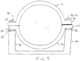
- Fig. 5 shows how two mould parts 21 in accordance with Fig. 3 can be laid against one another in order to secure a pipe (not shown).
- the side lugs 23, 24 of the two mould parts 21, which represent a component of the anchoring device, are secured by means of bolts 30 and washers 32 to the posts 34 of a foundation 35. In this manner they secure the position of the pipe 20.
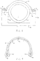
- Fig. 6 shows an alternative shape of the mounting apparatus 21, in which a structure, which also consists of three bands arranged above one another here, are placed around a corresponding mandrel in a circular mould part 21, with the ends of the bands being bent radially outwardly away from the center of the circular part at one point in order to form lugs 23, 24, so that a pipe 18 can be suspended by the so formed mounting apparatus from the structure 35, and indeed by a mounting bolt 30, which extends through the lugs formed by the radially outwardly bent parts of the straps, optionally through the intermediary of a washer (not shown in Fig. 6).
- Fig. 7 shows that the mounting apparatus can also have the form of a plurality of U-shaped hoops 21, which are arranged alongside one another and merge into one another, and which can be secured at the points 36 to a foundation 35 by means of bolts and pressure-distributing washers (not shown) so that several pipes 18 - in the example four pipes - can be arranged alongside one another.
- moulded parts 21 can be manufactured starting from the existing spectrum of bands or straps by the cutting of corresponding lengths from a long band 10 as a starting material. In this manner a rational manufacture of the moulded parts 21 is possible, and the starting material 10 can likewise be rationally manufactured.
- Fig. 8 shows a possibility of integrating a metal plate 40, for example a steel plate, into the mounting apparatus 21, so that this plate is at least substantially closed on all sides and can therefore not corrode, with the steel plate producing a stiffened region of the structure, which is expedient for the mounting to a corresponding foundation 35.
- the lower belt 10 is placed over the metal plate and secured to the band 10 at the upper side of the mounting apparatus.
- Fig. 9 shows an alternative type of anchoring in which the bands are formed into a loop-shape 42, which can then be secured, for example via a throughgoing bar 44 and bolt elements (not shown) to a foundation, and which thereby surround the pipe.
- the ends 46 of the bands are preferably arranged remote from the loops 42 in order to achieve the maximum strength of the loops.
- mounting apparatuses for the attachment of pipes 18 are shown. However, no restriction to the mounting of pipes is intended, since the mounting apparatus can also be used for the mounting of differently designed articles, provided that corresponding moulds are produced in order to produce correspondingly shaped moulded parts from the bands.
- thermoplastic covering becomes soft on heating
- this could have a grooved surface with the mounting apparatus having a complementary grooved surface after its removal from the mould.
- bands which form the middle layers of the finished structure can also be used, which consist of fiber materials which are less strong than the strings in the outer layers, and indeed without having to fear considerable penalties in the strength and bending strength of the finished mounting apparatus. It is also not necessary for all the strings or one band to consist of the same material. It is entirely possible to use different materials here in order to meet differing requirements. Thus, some of the strings can consist of a layer of favorably priced fibers, which normally have a lower strength. Such strings then, for example, satisfy the function of spacers rather than the function of load-carrying members.
- Fig. 10 illustrates an apparatus for the manufacture of a band having twelve strips each in the form of a multi-ply yarn or corded yarn.
- the plied yarn can e.g. be a 2-ply, a 3-ply or a multi-ply yarn.
- the material can be glass, aramide, PBO, Vectran, or other high performance fibers.
- the yarns are first coated with a thermoplastic resin in a cross-head extruder (not shown) and wound onto large reels 52 of a creel 50.
- the thermoplastic resin used can be of any known type, as long as it can be processed in an extruder.
- the shape of the outside of the plied yarns mentioned above ensures a good mechanical cohesion between the yarns and the thermoplastic resin.
- twelve coated yarns are used and are each wound onto a respective reel 52 of the creel 50.
- the coated yarns are drawn from the reels and led through a hot air oven 54, where the temperature is such that it corresponds to the softening temperature of the plastic.
- a die 56 which corresponds to the size and profile of the band 10 which is the result of the process.
- the die 56 has a size which ensures a good pressure in the material which is pulled through the die.
- a caterpillar pulling arrangement 58 (a caterpuller) is placed at an appropriate distance after the die. This arrangement comprises two recirculating belts or bands 62 which move in the directions shown by the arrows 60.
- the arrangement 58 pulls the whole band 10 and thereby the coated yarns through the process line.
- the band 10 can, e.g., be wound onto a drum for storage or can be processed immediately, while still warm, into a mounting structure of a mounting apparatus in accordance with the invention.
- the twelve plied aramide yarns can each consist of 3340 x 1 x 3 dtex 110s-65z coated with polypropylene thermoplastic resin.
- the hot air oven can have a temperature of 220° C corresponding to the melting temperature of the polypropylene.
- the die 56 can have a rectangular aperture of 3mm x 21mm and the resulting band has a rectangular cross section of the same size.
- the bands 10 When the bands 10 are processed into a structure, they are warmed up to a softening temperature which is less than the melting temperature. The application of a sufficiently high pressure then results in fusion of the thermoplastic coverings to one another . The fused coverings are essentially indistinguishable from a block of the thermoplastic material. Since melting does not take place, the strings remain substantially in the same positions in the structure as they had in the individual bands or band lengths. This applies to all variants of the invention, not just to the example given above. The pressures and softening temperatures have to be selected in accordance with the specified materials used.
Landscapes
- Engineering & Computer Science (AREA)
- General Engineering & Computer Science (AREA)
- Mechanical Engineering (AREA)
- Textile Engineering (AREA)
- Chemical & Material Sciences (AREA)
- Composite Materials (AREA)
- Lining Or Joining Of Plastics Or The Like (AREA)
- Clamps And Clips (AREA)
Applications Claiming Priority (2)
| Application Number | Priority Date | Filing Date | Title |
|---|---|---|---|
| DE19731946A DE19731946A1 (de) | 1997-07-24 | 1997-07-24 | Befestigungseinrichtung für Rohre und andere Gegenstände sowie Verfahren zu deren Herstellung |
| DE19731946 | 1997-07-24 |
Publications (2)
| Publication Number | Publication Date |
|---|---|
| EP0893637A2 true EP0893637A2 (fr) | 1999-01-27 |
| EP0893637A3 EP0893637A3 (fr) | 2000-05-10 |
Family
ID=7836820
Family Applications (1)
| Application Number | Title | Priority Date | Filing Date |
|---|---|---|---|
| EP98113893A Withdrawn EP0893637A3 (fr) | 1997-07-24 | 1998-07-24 | Dispositif de montage pour tuyaux et autres articles et méthode de fabrication |
Country Status (3)
| Country | Link |
|---|---|
| US (1) | US6098932A (fr) |
| EP (1) | EP0893637A3 (fr) |
| DE (1) | DE19731946A1 (fr) |
Families Citing this family (8)
| Publication number | Priority date | Publication date | Assignee | Title |
|---|---|---|---|---|
| DE19956736C1 (de) * | 1999-11-25 | 2001-07-26 | Kocks Drahtseilerei | Verfahren und Verseilvorrichtung zur Herstellung eines Seiles oder Seilelements sowie Seil oder Seilelement |
| US6478264B1 (en) * | 1999-12-14 | 2002-11-12 | Sonoco Development, Inc. | Peel test mandrel assembly and method |
| US6601802B1 (en) * | 1999-12-30 | 2003-08-05 | Lsp Products Group Inc | Method for making extruded acoustic pipe support |
| GB2385396B (en) * | 2002-02-11 | 2004-08-04 | Roblon Ind Fiber | A method for connecting two structures together using a strap and tensioning device for use in such a method |
| US6866449B2 (en) | 2003-03-26 | 2005-03-15 | Kevin Riddiough | Anchor block construction for an escape line |
| ITMI20052156A1 (it) * | 2005-11-11 | 2007-05-12 | Ruredil Spa | Manufatto edile e metodo di rinforzo di una struttura edile |
| US20140059810A1 (en) * | 2012-08-31 | 2014-03-06 | AKACAS IP Holdings, LLC | Bottle bracelet |
| WO2019207402A1 (fr) | 2018-04-26 | 2019-10-31 | 3M Innovative Properties Company | Enveloppe non adhésive comprenant un renforcement tissé pour conduites sous-marines |
Citations (2)
| Publication number | Priority date | Publication date | Assignee | Title |
|---|---|---|---|---|
| US3668740A (en) | 1970-11-27 | 1972-06-13 | Owens Corning Fiberglass Corp | High strength strap and method of making it |
| DE19522014A1 (de) | 1995-06-21 | 1997-01-02 | Huesker Synthetic Gmbh & Co | Verfahren und Vorrichtung zur Sicherung von Pipelines |
Family Cites Families (33)
| Publication number | Priority date | Publication date | Assignee | Title |
|---|---|---|---|---|
| DE7226076U (de) * | 1972-10-26 | Unionplastik Gmbh | Geräuschdämmende Einlage für Rohraufhängung | |
| US662935A (en) * | 1899-03-30 | 1900-12-04 | Harry H Hibberd | Plumber's tag or clamp-stay. |
| US1362244A (en) * | 1919-08-08 | 1920-12-14 | John W Farley | Pipe-hanger |
| US1455612A (en) * | 1921-06-08 | 1923-05-15 | Charles M Heeter | Pipe grip |
| US1466292A (en) * | 1922-05-10 | 1923-08-28 | Gen Fire Extinguisher Co | Pipe-anchoring means |
| US2003159A (en) * | 1933-04-05 | 1935-05-28 | Lamson Co | Pneumatic dispatch system |
| US1986861A (en) * | 1933-09-11 | 1935-01-08 | Electrical Eng Equipment Co | Cable supporting clamp |
| US2922733A (en) * | 1955-02-04 | 1960-01-26 | Richard A Henning | Cushion liner for a clamp operable at extreme temperatures |
| US2870501A (en) * | 1956-11-23 | 1959-01-27 | Joclin Mfg Company | Liners for hose clamps |
| DE1853241U (de) * | 1962-04-03 | 1962-06-14 | Helmut Euler Fa | Kabelschelle. |
| US3263947A (en) * | 1964-03-20 | 1966-08-02 | Kerttunen Tuomas | Clamp for conductors or the like |
| US3391050A (en) * | 1964-04-03 | 1968-07-02 | Douglas Aircraft Co Inc | Glass filament tape |
| US3475264A (en) * | 1964-07-21 | 1969-10-28 | Chase Donaldson | Reinforced plastic strapping laminate |
| DE1926532U (de) * | 1965-02-18 | 1965-11-04 | Wolfgang Stoer | Mehrfachschelle fuer rohre. |
| US3466219A (en) * | 1965-08-09 | 1969-09-09 | Us Air Force | Fiber reinforced plastic composite material |
| US3494849A (en) * | 1967-09-29 | 1970-02-10 | Cambridge Wire Cloth | Anchoring device |
| NL6915292A (fr) * | 1968-10-14 | 1970-04-16 | ||
| US3622429A (en) * | 1968-11-25 | 1971-11-23 | James A Kippan | Synthetic strap |
| US4018015A (en) * | 1975-10-20 | 1977-04-19 | Swanson Gladys B | Trailer anchoring device |
| JPS607166Y2 (ja) * | 1976-06-17 | 1985-03-09 | 宇部日東化成株式会社 | 帯状梱包用結束材 |
| DE2753243A1 (de) * | 1977-11-29 | 1979-06-07 | Bayer Ag | Bewehrung von armierten erdbauwerken |
| US4318518A (en) * | 1980-03-20 | 1982-03-09 | Davis Lynwood A | Insulated hanger strap |
| US4595450A (en) * | 1983-10-24 | 1986-06-17 | D.A.B. Industries, Inc. | Apparatus for making a brake-band |
| US4606687A (en) * | 1985-03-15 | 1986-08-19 | General Motors Corporation | Resilient tie-down device |
| US4627133A (en) * | 1985-08-08 | 1986-12-09 | Owens-Corning Fiberglas Corporation | Pultruded underground tank hold-down strap assembly |
| DE3639743A1 (de) * | 1986-11-21 | 1988-05-26 | Stefan Biffar | Geruestbrett und verfahren zu dessen herstellung |
| US4769875A (en) * | 1987-05-22 | 1988-09-13 | Hartman Dan E | Elastic reinforced tie-down strap and method of making the same |
| JPH01141925A (ja) * | 1987-11-30 | 1989-06-02 | Honshu Paper Co Ltd | パラ配向アラミド繊維シートを基材とする改良複合材料 |
| DE3904813A1 (de) * | 1989-02-17 | 1990-08-23 | Basf Ag | Faserverbundwerkstoff |
| US4960253A (en) * | 1989-05-04 | 1990-10-02 | Frederick Perrault | Compact lightweight wireway |
| US4999980A (en) * | 1989-12-26 | 1991-03-19 | Aerborn Equestrian Limited | Strap component |
| US5522571A (en) * | 1993-08-09 | 1996-06-04 | Hang It All Products | Pipe hanging strap |
| JP3344279B2 (ja) * | 1997-05-07 | 2002-11-11 | ヤマハ株式会社 | 制御装置 |
-
1997
- 1997-07-24 DE DE19731946A patent/DE19731946A1/de not_active Ceased
-
1998
- 1998-07-23 US US09/121,483 patent/US6098932A/en not_active Expired - Fee Related
- 1998-07-24 EP EP98113893A patent/EP0893637A3/fr not_active Withdrawn
Patent Citations (2)
| Publication number | Priority date | Publication date | Assignee | Title |
|---|---|---|---|---|
| US3668740A (en) | 1970-11-27 | 1972-06-13 | Owens Corning Fiberglass Corp | High strength strap and method of making it |
| DE19522014A1 (de) | 1995-06-21 | 1997-01-02 | Huesker Synthetic Gmbh & Co | Verfahren und Vorrichtung zur Sicherung von Pipelines |
Also Published As
| Publication number | Publication date |
|---|---|
| DE19731946A1 (de) | 1999-01-28 |
| EP0893637A3 (fr) | 2000-05-10 |
| US6098932A (en) | 2000-08-08 |
Similar Documents
| Publication | Publication Date | Title |
|---|---|---|
| US3668740A (en) | High strength strap and method of making it | |
| EP1592908B1 (fr) | Tuyau renforce de fibres | |
| EP0524206B1 (fr) | Tube composite a cellules multiples | |
| US4119748A (en) | Steel cord reinforced plastic materials | |
| CA2411113C (fr) | Ameliorations concernant un tuyau souple | |
| CA2076391E (fr) | Element tubulaire composite a fibres axiales adjacentes a la paroi | |
| US7650742B2 (en) | Cable made of high strength fiber composite material | |
| EP1678436B1 (fr) | Tuyau flexible comprenant une enveloppe externe permeable et son procede de fabrication | |
| EP2983900B1 (fr) | Corps de tuyau flexible et son procédé de fabrication | |
| US20020028112A1 (en) | Tension member | |
| AU2001264075A1 (en) | Improvements relating to hose | |
| US9481948B2 (en) | Robust pre-impregnated yarn for manufacturing textile composites | |
| CA2651575A1 (fr) | Ameliorations en rapport avec un tuyau | |
| JPH0718206B2 (ja) | 構造用ロッドの製造方法 | |
| EP0893637A2 (fr) | Dispositif de montage pour tuyaux et autres articles et méthode de fabrication | |
| JP3820031B2 (ja) | 繊維強化プラスチック製素線及びより線並びにそれらの製造方法 | |
| CA1276481C (fr) | Membre d'armature a saillie en surface | |
| US4679600A (en) | High tensile strength removable hose covering | |
| EP1446603B1 (fr) | Conduite flexible a armature de traction | |
| WO2003033814A1 (fr) | Procede de production d'un element structural allonge | |
| BR0007685B1 (pt) | processo de realização de um cabo de fixação compósito, notadamente para plataforma marìtima, e cabo de fixação compósito, notadamente para plataforma marìtima. | |
| JPH0335550B2 (fr) | ||
| JP3669938B2 (ja) | 熱可塑性樹脂被覆frp製幅止め材の製造方法 | |
| GB2402944A (en) | Methods for transporting and installing composite tether | |
| JPS63143513A (ja) | 繊維強化プラスチツク線条体の接続方法 |
Legal Events
| Date | Code | Title | Description |
|---|---|---|---|
| PUAI | Public reference made under article 153(3) epc to a published international application that has entered the european phase |
Free format text: ORIGINAL CODE: 0009012 |
|
| AK | Designated contracting states |
Kind code of ref document: A2 Designated state(s): AT BE CH CY DE DK ES FI FR GB GR IE IT LI LU MC NL PT SE |
|
| AX | Request for extension of the european patent |
Free format text: AL;LT;LV;MK;RO;SI |
|
| PUAL | Search report despatched |
Free format text: ORIGINAL CODE: 0009013 |
|
| AK | Designated contracting states |
Kind code of ref document: A3 Designated state(s): AT BE CH CY DE DK ES FI FR GB GR IE IT LI LU MC NL PT SE |
|
| AX | Request for extension of the european patent |
Free format text: AL;LT;LV;MK;RO;SI |
|
| AKX | Designation fees paid | ||
| STAA | Information on the status of an ep patent application or granted ep patent |
Free format text: STATUS: THE APPLICATION IS DEEMED TO BE WITHDRAWN |
|
| 18D | Application deemed to be withdrawn |
Effective date: 20001111 |
|
| REG | Reference to a national code |
Ref country code: DE Ref legal event code: 8566 |