EP0893909B1 - Dispositif de formation d'image - Google Patents
Dispositif de formation d'image Download PDFInfo
- Publication number
- EP0893909B1 EP0893909B1 EP98305883A EP98305883A EP0893909B1 EP 0893909 B1 EP0893909 B1 EP 0893909B1 EP 98305883 A EP98305883 A EP 98305883A EP 98305883 A EP98305883 A EP 98305883A EP 0893909 B1 EP0893909 B1 EP 0893909B1
- Authority
- EP
- European Patent Office
- Prior art keywords
- toner
- image
- image data
- amount
- forming device
- Prior art date
- Legal status (The legal status is an assumption and is not a legal conclusion. Google has not performed a legal analysis and makes no representation as to the accuracy of the status listed.)
- Expired - Lifetime
Links
Images



Classifications
-
- G—PHYSICS
- G03—PHOTOGRAPHY; CINEMATOGRAPHY; ANALOGOUS TECHNIQUES USING WAVES OTHER THAN OPTICAL WAVES; ELECTROGRAPHY; HOLOGRAPHY
- G03G—ELECTROGRAPHY; ELECTROPHOTOGRAPHY; MAGNETOGRAPHY
- G03G15/00—Apparatus for electrographic processes using a charge pattern
-
- H—ELECTRICITY
- H04—ELECTRIC COMMUNICATION TECHNIQUE
- H04N—PICTORIAL COMMUNICATION, e.g. TELEVISION
- H04N1/00—Scanning, transmission or reproduction of documents or the like, e.g. facsimile transmission; Details thereof
- H04N1/23—Reproducing arrangements
- H04N1/2307—Circuits or arrangements for the control thereof, e.g. using a programmed control device, according to a measured quantity
- H04N1/233—Circuits or arrangements for the control thereof, e.g. using a programmed control device, according to a measured quantity according to characteristics of the data to be reproduced, e.g. number of lines
-
- G—PHYSICS
- G03—PHOTOGRAPHY; CINEMATOGRAPHY; ANALOGOUS TECHNIQUES USING WAVES OTHER THAN OPTICAL WAVES; ELECTROGRAPHY; HOLOGRAPHY
- G03G—ELECTROGRAPHY; ELECTROPHOTOGRAPHY; MAGNETOGRAPHY
- G03G15/00—Apparatus for electrographic processes using a charge pattern
- G03G15/14—Apparatus for electrographic processes using a charge pattern for transferring a pattern to a second base
- G03G15/16—Apparatus for electrographic processes using a charge pattern for transferring a pattern to a second base of a toner pattern, e.g. a powder pattern, e.g. magnetic transfer
- G03G15/1665—Apparatus for electrographic processes using a charge pattern for transferring a pattern to a second base of a toner pattern, e.g. a powder pattern, e.g. magnetic transfer by introducing the second base in the nip formed by the recording member and at least one transfer member, e.g. in combination with bias or heat
- G03G15/167—Apparatus for electrographic processes using a charge pattern for transferring a pattern to a second base of a toner pattern, e.g. a powder pattern, e.g. magnetic transfer by introducing the second base in the nip formed by the recording member and at least one transfer member, e.g. in combination with bias or heat at least one of the recording member or the transfer member being rotatable during the transfer
- G03G15/1675—Apparatus for electrographic processes using a charge pattern for transferring a pattern to a second base of a toner pattern, e.g. a powder pattern, e.g. magnetic transfer by introducing the second base in the nip formed by the recording member and at least one transfer member, e.g. in combination with bias or heat at least one of the recording member or the transfer member being rotatable during the transfer with means for controlling the bias applied in the transfer nip
-
- G—PHYSICS
- G03—PHOTOGRAPHY; CINEMATOGRAPHY; ANALOGOUS TECHNIQUES USING WAVES OTHER THAN OPTICAL WAVES; ELECTROGRAPHY; HOLOGRAPHY
- G03G—ELECTROGRAPHY; ELECTROPHOTOGRAPHY; MAGNETOGRAPHY
- G03G15/00—Apparatus for electrographic processes using a charge pattern
- G03G15/20—Apparatus for electrographic processes using a charge pattern for fixing, e.g. by using heat
- G03G15/2003—Apparatus for electrographic processes using a charge pattern for fixing, e.g. by using heat using heat
-
- H—ELECTRICITY
- H04—ELECTRIC COMMUNICATION TECHNIQUE
- H04N—PICTORIAL COMMUNICATION, e.g. TELEVISION
- H04N1/00—Scanning, transmission or reproduction of documents or the like, e.g. facsimile transmission; Details thereof
- H04N1/23—Reproducing arrangements
- H04N1/29—Reproducing arrangements involving production of an electrostatic intermediate picture
- H04N1/295—Circuits or arrangements for the control thereof, e.g. using a programmed control device, according to a measured quantity
-
- G—PHYSICS
- G03—PHOTOGRAPHY; CINEMATOGRAPHY; ANALOGOUS TECHNIQUES USING WAVES OTHER THAN OPTICAL WAVES; ELECTROGRAPHY; HOLOGRAPHY
- G03G—ELECTROGRAPHY; ELECTROPHOTOGRAPHY; MAGNETOGRAPHY
- G03G2215/00—Apparatus for electrophotographic processes
- G03G2215/01—Apparatus for electrophotographic processes for producing multicoloured copies
- G03G2215/0167—Apparatus for electrophotographic processes for producing multicoloured copies single electrographic recording member
- G03G2215/0174—Apparatus for electrophotographic processes for producing multicoloured copies single electrographic recording member plural rotations of recording member to produce multicoloured copy
- G03G2215/0177—Rotating set of developing units
-
- G—PHYSICS
- G03—PHOTOGRAPHY; CINEMATOGRAPHY; ANALOGOUS TECHNIQUES USING WAVES OTHER THAN OPTICAL WAVES; ELECTROGRAPHY; HOLOGRAPHY
- G03G—ELECTROGRAPHY; ELECTROPHOTOGRAPHY; MAGNETOGRAPHY
- G03G2215/00—Apparatus for electrophotographic processes
- G03G2215/16—Transferring device, details
- G03G2215/1604—Main transfer electrode
- G03G2215/1619—Transfer drum
Definitions
- the present invention relates to an image forming device and, more particularly, to an image forming device such as a laser printer, and a method of operation, for forming an image on a recordable medium..
- US 5724627 discloses an image forming device for forming an image on a recordable medium such as a sheet of paper. Present image data is used to determine an amount of toner which must be replenished for the next image.
- a charging roller rotates and evenly charges a photosensitive surface which is spread over the outer periphery of a drum, to a high voltage.
- a laser beam is transmitted from an exposing unit, onto the charged photosensitive body, so as to form an electrostatic latent image.
- a laser source may include a laser diode, used to convert a digital signal into the laser beam.
- the electrostatic latent image formed on the photosensitive drum is then developed by adding a toner and passing through a developer to change the latent image to a visible image.
- the visible image is transferred onto a recordable medium, such as paper, which is transported and fed by a pickup roller.
- the visible image transferred onto the recordable medium is then fixed onto the recordable medium by heat and pressure of a fixing unit, and the recordable medium is then output from the image forming device, carrying the printed image.
- a warm-up step is performed during a predetermined time, according to the characteristics of the device. After completing the warm-up step, an on-line mode is set, and the device is then capable of performing a print command. If a print command is not received within a pre-set time in the on-line mode, the device is placed in a standby mode. When a print command is received in the standby mode, a warm-up step is performed before the printing operation is performed.
- the aforesaid conventional image forming device has the following problems.
- the fixing temperature of the fixing unit is not controlled according to the amount of toner transferred onto the recordable medium. Instead, the fixing temperature varies according to the kind of the recordable medium such as a normal paper or a transparent paper.
- the large amount of toner to be fixed causes a variation in the temperature of the fixing unit, thereby degrading the print quality.
- the electric potential of the transferring voltage is predetermined. If a large amount of toner is transferred onto the recordable medium, the predetermined electric potential may be insufficient for effective transfer of toner, a poor transfer of toner occurs and the print quality is thereby degraded.
- a method of operating an image forming device to form images using toner comprising the steps of:
- an image forming device for forming images using toner, comprising:
- the image forming device includes an input unit 1 for inputting print information; an image processing unit 4; and an image forming unit 10.
- the image processing unit 4 includes an image processor 2 for converting the print information from the input unit 1 into bitmapped image data, and a calculating unit 3 for calculating the size of the bitmapped image data.
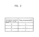
- the image forming unit 10 includes: a memory 5 for storing a table relating fixing temperature values according to an estimated amount of toner to be used; a central processor 6 for estimating the amount of toner to be used, from the size of the image data as calculated by the image processing unit 4, retrieving a fixing temperature value corresponding to the calculated amount of toner to be used from the memory 5 and outputting a control signal for controlling the fixing temperature accordingly; a fixing temperature controller 7 for controlling the fixing temperature of a fixing unit (not shown) according to the control signal from the central processor 6; a printer engine 8 for printing the bitmapped image data transmitted from the central processor 6 as an image; and a display 9 for displaying the operation state of the system according to various control signals from the central processor 6.
- FIG. 2 shows fixing temperature values according to the calculated estimated amount of toner to be used, as stored in form of table in the memory 5. Increasing estimated amounts of toner to be used correspond to increasing fixing temperatures.
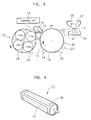
- FIG. 3 shows the structure of the printer engine 8.
- a photosensitive drum 11 is supported by a rotary body (not shown).
- the photosensitive drum is covered with a photosensitive body having a thin photosensitive layer spread on a conductive plate.
- the photosensitive drum 11 is arranged so as to be rotatably operated by a driving unit (not shown).
- a charging unit 12 for charging the surface of the photosensitive drum 11 with a certain electric potential
- an exposing unit 13 for forming an electrostatic latent image by radiating light such as laser light from a laser diode, on the surface of the photosensitive drum 11
- a developing unit 14 and a first cleaning unit 15 for removing remaining toner from the surface of the photosensitive drum 11.
- Developing unit 14 is rotated in contact with the photosensitive drum 11. An even pressure is applied, and the developer repeatedly forms four colour toner images, i.e. visible images successively formed according to the electrostatic latent image formed on the surface of the photosensitive drum 11.
- a transfer unit 16 includes a rotatable transfer drum 17 (FIG. 4).
- the transfer drum 17 is rotated, in contact with the photosensitive drum 11 with a predetermined pressure.
- FIG. 4 shows the transfer drum 17 used in the transfer unit 16.
- the transfer unit includes a transfer cylinder 18 and a dielectric sheet 19, such as a sheet of a PET or a PVDF attached to the transfer cylinder 18.
- a transferable medium i.e. a recordable medium 20 is attached on the surface of the transfer drum 17, electrostatically or mechanically.
- a transfer voltage By applying a transfer voltage on the transfer cylinder 18 of the transfer drum 17, the toner image which is formed on the photosensitive body of the photosensitive drum 11 is transferred onto the recordable medium 20.
- a paper separating finger 21 is located at the upper part of the transfer drum 17.
- an edge of the separating finger 21 in contact with the surface of the transfer drum 17 separates the recordable medium 20 from the transfer drum 17.
- a second cleaning unit 23 is located so as to clean the surface of the transfer drum 17 after transfer.
- an anti-electrostatic unit 22 is formed at a position facing the transfer drum 17 to eliminate the static electricity (charges) from the transfer drum 17, which finishes the transfer operation.
- a adhesion roller 24 is located adjacent to a point where the recordable medium 20 enters the image forming device so as to press the recordable medium into contact with the transfer drum 17. It applies an adhering voltage to the transfer drum 17 so that the recordable medium 20 adheres to the transfer drum 17.
- the recordable medium 20 separated from the transfer drum 17 passes through a fixing unit 25 between a heat roller 26 and a pressing roller 27.
- the toner image is thereby fixed onto the recordable medium 20.
- the developing unit 14 includes: a rotatable turret; four developers 14a to 14d which each respectively contain a yellow toner, a magenta toner, a cyan toner and a black toner; and a developer supporting body 28 of a cylindrical shape which supports the four developers.
- the turret of the rotatable developing unit 14 is rotated in a certain direction and the developers 14a to 14d move so as to sequentially face the surface of the photosensitive drum 11, thereby forming the electrostatic latent image on the surface of the photosensitive drum 11.
- a remaining toner amount sensor 29 is provided for detecting the toner amount remaining in each developer 14a to 14d of the developing unit 14.
- the remaining toner amount sensor 29 includes a light emitting element for transmitting light to the developer being measured, at a predetermined angle; a light receiving element for receiving light reflected by the developer being measured; and a holder for supporting the light emitting element and the light receiving element. The amount of light reflected is converted into an electrical signal corresponding to the quantity of light reflected, and therefore to the amount of toner remaining.
- the recordable medium 20 which is fed and transported by a pickup roller of a feeding unit (not shown)is adhered to the surface of the dielectric sheet 19 of the transfer drum 17 by the adhesion voltage of the adhesion roller.
- the charging unit 12 charges the surface of the rotating photosensitive drum 11 with a predetermined electric potential, and the exposing unit including a light source such as a laser diode, exposes an image of a first colour, e.g. yellow, based on the image information and then forms an electrostatic latent image corresponding to the yellow colour on the photosensitive body of the photosensitive drum 11.
- the developers 14a to 14d are successively carried into contact with the surface of the photosensitive drum 11 by suitably rotating the turret of the rotatable developing unit 14.
- An electrostatic latent yellow image formed on the surface of the photosensitive drum 11 is developed by the yellow toner of developer 14a, and thereby a visible yellow image is formed on the photosensitive drum 11.
- the visible yellow image generated by the toner image from the developing unit 14a is rotated to a position facing the transfer drum 17 of the transfer unit 16, i.e. into a developing position.
- the visible, yellow toner image is rotated and transferred onto the recordable medium 20 which is adhered to the dielectric sheet 19 of the transfer drum 17 by the transfer voltage applied to the transfer cylinder 18.
- Any yellow toner remaining on the surface of the photosensitive drum 11 is removed by the first cleaning unit 15, and the photosensitive drum 11 returns to a state capable of forming an image corresponding to the next colour.
- the turret of the rotatable developing unit 14 is rotated, so as to carry the next developer 14d, corresponding to magenta, to a position facing the surface of the photosensitive drum 11.
- the electrostatic latent magenta image formed on the surface of the photosensitive drum 11 becomes the visible magenta image by developing with toner of the second colour, magenta, by the developer 14d by the aforesaid method.
- the magenta toner image is transferred by the transferring voltage of the transfer cylinder 18, onto the surface of the recordable medium 20, onto which the yellow colour was previously transferred in a previous rotation of transfer cylinder 18.
- the separating finger 21 is used to separate the recordable medium 20 from the transfer unit 16.
- the toner images of all four colours are fixed onto the recordable medium 20 by heating to a predetermined temperature by the heat roller 26 of the fixing unit 25, and the recordable medium 20 is ejected to a paper eject orifice (not shown), thereby completing the printing operation.
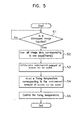
- step S1 the image forming device detects whether coded print information is input to the image processing unit 4 through the input unit 1, and converts the print information into bitmapped image data by the image processor 2.
- step S2 the calculating unit 3 adds, or sums, all the image data corresponding to one page, i.e. frame.
- step S3 the calculating unit 3 accordingly calculates an estimated amount of toner to be used.
- step S4 the estimated amount of toner to be used is transmitted to the central processor 6, and the central processor 6 reads a corresponding fixing temperature from the memory 5.
- step S5 the heating of the fixing unit 25 is controlled according to the fixing temperature read. As a result, effective fixing can be achieved, as the fixing temperature may be adapted for optimally fixing the amount of toner used.
- FIG. 6 is a block diagram illustrating another embodiment of the image forming device according to the present invention. This figure is similar to FIG. 1, and corresponding reference numerals indicate corresponding parts or features.
- the image forming unit 10 includes: a memory 5 for storing a table of transfer voltage values according to the estimated amounts of toner to be used; the central processor 6 for calculating an estimated amount of toner to be used, from the size of the bitmapped image data supplied by the image processing unit 4, reading a transfer voltage from the table stored in the memory 5, and outputting a control signal for accordingly controlling the transfer voltage; a transfer voltage generator 30 which controls the transfer voltage of the transfer unit in accordance with the control signal output from the central processor 6; the printer engine 8 for printing bitmapped image data transmitted from the central processor 6 as image information; and the display 9 for displaying the operation state of the system according to various control signals from the central processor 6.
- the structure of the printer engine 8 is similar to that of the printer engine 8 previously illustrated in FIG. 3.
- FIG. 7 shows a table of transfer voltage values according to the estimated amount of toner consumed as stored in the memory 5. As the estimated amount of toner consumed increases, the transferring voltage level also increases.
- step S6 the image forming device detects whether print information is input to the image processing unit 4 through the input unit 1, and is converted into bitmapped image data by the image processor 2.
- step S7 the calculating units adds, or sums, all the bitmap image data corresponding to one page, i.e. frame.
- step S8 the calculating unit accordingly calculates the estimated amount of toner consumed.
- step S9 the estimated amount of toner to be used is transmitted to the central processor 6 and the central processor 6 reads a transfer voltage value corresponding to the estimated amount of toner to be used from the memory 5.
- step S10 a transfer voltage value is supplied to the transfer unit 16 according to the transfer voltage read from memory 5.
- the transfer voltage is adapted according to the estimated amount of toner to be transferred, and efficient transfer of toner is thereby assured.
- the simple operation of summing all bit values in the bitmap provides an accurate estimation of the amount of toner that will be used when the bitmap image data is developed.
- an estimate of the total amount of toner used in printing a colour image may be obtained.
- the image forming device according to the present invention has the following benefits.
- the first embodiment of the invention by estimating the amount of toner which is transferred onto the recordable medium, and correspondingly controlling the fixing temperature of the fixing unit, poor fixing is prevented and an optimum print state can be maintained.
- the transfer is optimised and an optimum print state can be maintained.
- the present invention may be adapted for use with monochrome printers, by simply summing bitmap data corresponding to the single colour used, and controlling the fixing temperature and/or the transfer voltage accordingly.
Landscapes
- Physics & Mathematics (AREA)
- General Physics & Mathematics (AREA)
- Engineering & Computer Science (AREA)
- Multimedia (AREA)
- Signal Processing (AREA)
- Control Or Security For Electrophotography (AREA)
- Fixing For Electrophotography (AREA)
- Electrostatic Charge, Transfer And Separation In Electrography (AREA)
- Color Electrophotography (AREA)
Claims (10)
- Procédé d'utilisation d'un dispositif de formation d'images destiné à former des images en utilisant du toner, comprenant les étapes consistant à :fournir des données d'images en mode point correspondant à une image ; etestimer (S1-S3 ; S6-S8) une quantité de toner devant être utilisée pour la formation de ladite image en fonction desdites données d'image ;caractérisé parla sélection d'une valeur (S5 ; S10) pour au moins une d'une température de fixage et/ou d'une tension de transfert du dispositif de formation d'images en fonction de la quantité estimée de toner devant être utilisée ;définir la température de fixage et/ou la tension de transfert à ladite valeur sélectionnée respective ; etimprimer les données d'image en tant que ladite image avec ladite température de fixage et/ou tension de transfert définie(s) à la valeur sélectionnée respective.
- Procédé selon la revendication 1, dans lequel la quantité de toner devant être utilisée est estimée par un procédé comprenant les étapes consistant à :fournir des données d'image en mode point correspondant à ladite image, au format bitmap ;additionner (S2 ; S7) l'ensemble des valeurs de bits des données d'image en mode point ; etestimer la quantité de toner devant être utilisée selon les données d'image en mode point additionnées.
- Procédé selon la revendication 1 destiné à former des images couleur à partir d'une pluralité de toners colorés (14a-14d), dans lequel la quantité de toner devant être utilisée est estimée par un procédé comprenant les étapes consistant à :prévoir (2), pour chacun de la pluralité de toners colorés, des données d'image en mode point correspondant à la partie de ladite image devant être formée à partir de ce toner coloré, au format bitmap ;additionner (3 ; S2 ; S7) les données d'image en mode point pour chacun de la pluralité de toners colorés pour fournir des données d'image en mode point additionnées pour l'ensemble de ladite image ; etestimer une quantité totale de toner devant être utilisée selon les données en mode point additionnées, la température de fixage étant définie à une valeur en fonction de ladite quantité totale.
- Procédé selon la revendication 1 ou la revendication 3, destiné à former des images couleur à partir d'une pluralité de toners colorés (14a-14d), dans lequel la quantité de toner devant être utilisée est estimée par un procédé comprenant les étapes consistant à :prévoir (2), pour chacun de la pluralité de toners colorés, des données d'image en mode point correspondant à la partie de ladite image devant être formée à partir de ce toner coloré, au format bitmap ;additionner (3 ; S2 ; S7) les données d'image en mode point pour chacun de la pluralité de toners colorés pour fournir des données d'image en mode point additionnées pour chaque couleur de l'ensemble de ladite image ; etestimer, pour chaque couleur, la quantité de toner respectif devant être utilisée selon les données en mode point additionnées respectives pour chaque couleur ; etdéfinir, pour chaque couleur, la tension de transfert dudit dispositif de formation d'images à une valeur en fonction de la quantité estimée de toner respectif.
- Procédé selon l'une quelconque des revendications précédentes, dans lequel une augmentation de la quantité estimée de toner devant être utilisée entraîne une augmentation de la température de fixage du dispositif de formation d'images.
- Procédé selon l'une quelconque des revendications précédentes, dans lequel une augmentation de la quantité estimée de toner devant être utilisée entraîne une augmentation de la tension de transfert du dispositif de formation d'image.
- Procédé selon l'une quelconque des revendications précédentes, dans lequel une table est formée dans une mémoire (5), et la quantité estimée de toner devant être utilisée (A, B, C) est utilisée pour accéder et lire une valeur correspondante (a, b, c) de l'au moins un paramètre de fonctionnement à partir du tableau.
- Procédé selon la revendication 2, 3 ou 4 et n'importe quelle revendication dépendante de celle-ci, dans lequel des données d'image sont fournies (1) au dispositif de formation d'images, et sont converties par un processeur d'image (2) au format bitmap.
- Dispositif de formation d'images destiné à former des images en utilisant du toner, comprenant :des moyens pour fournir des données d'image en mode point correspondant à une image ; etdes moyens (2, 3) pour estimer une quantité de toner devant être utilisée pour former ladite image en fonction desdites données d'image ; et caractérisé pardes moyens (7 ; 30) pour sélectionner une valeur pour au moins une d'une température de fixage et/ou d'une tension de transfert du dispositif de formation d'images en fonction de la quantité estimée de toner devant être utilisée ;des moyens pour définir la température de fixage et/ou la tension de transfert à ladite valeur sélectionnée respective ; etledit dispositif est conçu pour imprimer les données d'image en tant que ladite image, avec ladite température de fixage et/ou tension de transfert définie(s) à une valeur sélectionnée respective.
- Dispositif de formation d'image selon la revendication 9, dans lequel ladite image est formée sur un support enregistrable (10) sous la forme d'une feuille.
Applications Claiming Priority (2)
| Application Number | Priority Date | Filing Date | Title |
|---|---|---|---|
| KR1019970034388A KR100228714B1 (ko) | 1997-07-23 | 1997-07-23 | 화상형성장치 |
| KR9734388 | 1997-07-23 |
Publications (3)
| Publication Number | Publication Date |
|---|---|
| EP0893909A2 EP0893909A2 (fr) | 1999-01-27 |
| EP0893909A3 EP0893909A3 (fr) | 2001-05-23 |
| EP0893909B1 true EP0893909B1 (fr) | 2006-08-09 |
Family
ID=36934174
Family Applications (1)
| Application Number | Title | Priority Date | Filing Date |
|---|---|---|---|
| EP98305883A Expired - Lifetime EP0893909B1 (fr) | 1997-07-23 | 1998-07-23 | Dispositif de formation d'image |
Country Status (5)
| Country | Link |
|---|---|
| US (1) | US6104893A (fr) |
| EP (1) | EP0893909B1 (fr) |
| KR (1) | KR100228714B1 (fr) |
| CN (1) | CN1166990C (fr) |
| DE (1) | DE69835485T2 (fr) |
Families Citing this family (18)
| Publication number | Priority date | Publication date | Assignee | Title |
|---|---|---|---|---|
| US6356359B1 (en) * | 1998-01-20 | 2002-03-12 | Electronics For Imaging, Inc | Toner usage estimation system |
| US6636708B2 (en) * | 2001-08-21 | 2003-10-21 | Kabushiki Kaisha Toshiba | Image forming apparatus and system with a transfer device having an adjustable transfer bias |
| US7063469B2 (en) | 2002-04-19 | 2006-06-20 | Sharp Kabushiki Kaisha | Image output apparatus for providing stable operation |
| US7466303B2 (en) * | 2004-02-10 | 2008-12-16 | Sunnybrook Health Sciences Center | Device and process for manipulating real and virtual objects in three-dimensional space |
| JP2005231145A (ja) * | 2004-02-18 | 2005-09-02 | Sharp Corp | 画像形成装置及び画像形成システム |
| JP4280694B2 (ja) * | 2004-09-07 | 2009-06-17 | キヤノン株式会社 | 画像形成装置 |
| JP4175346B2 (ja) * | 2005-06-30 | 2008-11-05 | ブラザー工業株式会社 | 画像変換プログラム、制御方法、および画像データ処理システム |
| JP4844152B2 (ja) | 2006-02-13 | 2011-12-28 | 富士ゼロックス株式会社 | 画像形成装置シミュレーション装置、画像形成装置シミュレーション方法及びプログラム |
| KR20080086301A (ko) * | 2007-03-22 | 2008-09-25 | 삼성전자주식회사 | 화상 형성 장치 및 그 제어 방법 |
| JP5538669B2 (ja) * | 2007-08-31 | 2014-07-02 | キヤノン株式会社 | 画像形成装置、画像形成装置の制御方法、記憶媒体及びプログラム |
| KR20090089641A (ko) * | 2008-02-19 | 2009-08-24 | 삼성전자주식회사 | 단말장치, 화상형성장치 및 이들을 포함하는 인쇄시스템과인쇄 방법 |
| JP5043762B2 (ja) * | 2008-04-24 | 2012-10-10 | キヤノン株式会社 | 印刷制御装置、印刷制御方法及びプログラム |
| JP2013025218A (ja) * | 2011-07-25 | 2013-02-04 | Ricoh Co Ltd | 画像形成装置、画像形成方法、及び画像形成プログラム |
| JP2013025219A (ja) | 2011-07-25 | 2013-02-04 | Ricoh Co Ltd | 画像形成装置、画像形成方法、及び画像形成プログラム |
| JP6334872B2 (ja) * | 2013-09-11 | 2018-05-30 | キヤノン株式会社 | 画像形成装置、制御装置およびそれらの制御方法 |
| JP6164232B2 (ja) * | 2015-01-26 | 2017-07-19 | コニカミノルタ株式会社 | 画像形成装置、画像形成装置の制御方法およびプログラム |
| JP6755698B2 (ja) * | 2016-04-22 | 2020-09-16 | キヤノン株式会社 | 画像形成装置 |
| JP7305393B2 (ja) * | 2019-03-26 | 2023-07-10 | キヤノン株式会社 | 画像形成装置、画像形成方法及びプログラム |
Family Cites Families (17)
| Publication number | Priority date | Publication date | Assignee | Title |
|---|---|---|---|---|
| JPS59123857A (ja) * | 1982-12-29 | 1984-07-17 | Canon Inc | 画像再生制御装置 |
| JPS59152471A (ja) * | 1983-02-18 | 1984-08-31 | Matsushita Electric Ind Co Ltd | 静電複写機 |
| JPS61267074A (ja) * | 1985-05-21 | 1986-11-26 | Fuji Electric Co Ltd | 転写装置 |
| JP2744788B2 (ja) * | 1988-03-22 | 1998-04-28 | 株式会社日立製作所 | 定着制御装置 |
| JP2941827B2 (ja) * | 1988-12-15 | 1999-08-30 | キヤノン株式会社 | 記録装置 |
| DE4019543A1 (de) * | 1989-06-20 | 1991-01-10 | Canon Kk | Dokument-verarbeitungsgeraet |
| JPH04240886A (ja) * | 1991-01-25 | 1992-08-28 | Nippon Electron Kogyo Kk | トナー定着温度制御装置 |
| JPH04335383A (ja) * | 1991-05-10 | 1992-11-24 | Ricoh Co Ltd | 画像形成装置 |
| JPH05333728A (ja) * | 1992-05-28 | 1993-12-17 | Canon Inc | 画像形成装置 |
| US5296904A (en) * | 1993-03-31 | 1994-03-22 | Xerox Corporation | Three-roll fuser with center pressure roll for black and color application |
| JPH0883015A (ja) * | 1994-09-14 | 1996-03-26 | Toshiba Corp | 定着装置 |
| JP3113561B2 (ja) * | 1995-10-30 | 2000-12-04 | キヤノン株式会社 | 画像形成装置 |
| US5745658A (en) * | 1995-11-16 | 1998-04-28 | Datastrip Products Inc. | Method of aligning one dimensional or two dimensional codes to printer pixels |
| JPH09160364A (ja) * | 1995-12-12 | 1997-06-20 | Ricoh Co Ltd | 画像形成装置 |
| JPH09197893A (ja) * | 1996-01-12 | 1997-07-31 | Canon Inc | 画像形成装置 |
| JPH09244424A (ja) * | 1996-03-13 | 1997-09-19 | Minolta Co Ltd | 画像形成装置 |
| JP3834866B2 (ja) * | 1996-04-26 | 2006-10-18 | コニカミノルタホールディングス株式会社 | 画像形成装置及び画像形成方法並びに画像形成装置制御方法 |
-
1997
- 1997-07-23 KR KR1019970034388A patent/KR100228714B1/ko not_active Expired - Fee Related
-
1998
- 1998-07-23 DE DE69835485T patent/DE69835485T2/de not_active Expired - Lifetime
- 1998-07-23 US US09/121,156 patent/US6104893A/en not_active Expired - Lifetime
- 1998-07-23 CN CNB981161618A patent/CN1166990C/zh not_active Expired - Fee Related
- 1998-07-23 EP EP98305883A patent/EP0893909B1/fr not_active Expired - Lifetime
Also Published As
| Publication number | Publication date |
|---|---|
| EP0893909A2 (fr) | 1999-01-27 |
| DE69835485D1 (de) | 2006-09-21 |
| KR19990011328A (ko) | 1999-02-18 |
| KR100228714B1 (ko) | 1999-11-01 |
| CN1206141A (zh) | 1999-01-27 |
| EP0893909A3 (fr) | 2001-05-23 |
| CN1166990C (zh) | 2004-09-15 |
| US6104893A (en) | 2000-08-15 |
| DE69835485T2 (de) | 2007-03-08 |
Similar Documents
| Publication | Publication Date | Title |
|---|---|---|
| EP0893909A2 (fr) | Dispositif de formation d'image | |
| EP0298506B1 (fr) | Appareil de formation d'images | |
| US6081678A (en) | Image forming apparatus and method to detect amount of toner adhered to a toner image | |
| JPH06175452A (ja) | 電子写真装置 | |
| US6188852B1 (en) | Process cartridge and image forming apparatus on which the process cartridge is mountable | |
| EP0745909B1 (fr) | Imprimante électrophotographique par ligne couleur | |
| JP4023573B2 (ja) | 画像形成装置 | |
| EP0863458B1 (fr) | Procédé de commande et appareil d'impression | |
| US6175698B1 (en) | Toner concentration control for an imaging system | |
| JPH0614687B2 (ja) | カラ−画像記録装置 | |
| US6112036A (en) | Image forming apparatus for judging life of photosensitive member based on revolution number of intermediate transfer member | |
| US6253037B1 (en) | Apparatus and method for optimizing image transfer environment in an electrophotographic system | |
| US6122461A (en) | Image processing apparatus and control method therefor | |
| US6169861B1 (en) | Feedback toner concentration control for an imaging system | |
| US6167213A (en) | Feedback toner concentration control for an imaging system | |
| US6104890A (en) | Electrophotographic device and density control method thereof | |
| JP2002287581A (ja) | 画像形成装置、カートリッジ及び画像形成方法 | |
| US6173133B1 (en) | Feedback toner concentration control for an imaging system | |
| US6160971A (en) | Feed forward and feedback toner concentration control for an imaging system | |
| US6967742B1 (en) | Printer server, method for processing data and storage medium | |
| KR100325815B1 (ko) | 화상형성장치의 화상품질 향상방법 | |
| US5164781A (en) | Color image electrophotographic apparatus for printing long-size copy images | |
| US7149448B2 (en) | Image forming apparatus having a plurality of developing means | |
| US20050100369A1 (en) | Image forming apparatus and a control method thereof | |
| US7106989B2 (en) | Method and apparatus for controlling high-voltage output in image forming system |
Legal Events
| Date | Code | Title | Description |
|---|---|---|---|
| PUAI | Public reference made under article 153(3) epc to a published international application that has entered the european phase |
Free format text: ORIGINAL CODE: 0009012 |
|
| 17P | Request for examination filed |
Effective date: 19980810 |
|
| AK | Designated contracting states |
Kind code of ref document: A2 Designated state(s): DE FR GB |
|
| AX | Request for extension of the european patent |
Free format text: AL;LT;LV;MK;RO;SI |
|
| PUAL | Search report despatched |
Free format text: ORIGINAL CODE: 0009013 |
|
| AK | Designated contracting states |
Kind code of ref document: A3 Designated state(s): AT BE CH CY DE DK ES FI FR GB GR IE IT LI LU MC NL PT SE |
|
| AX | Request for extension of the european patent |
Free format text: AL;LT;LV;MK;RO;SI |
|
| AKX | Designation fees paid |
Free format text: DE FR GB |
|
| 17Q | First examination report despatched |
Effective date: 20050502 |
|
| GRAP | Despatch of communication of intention to grant a patent |
Free format text: ORIGINAL CODE: EPIDOSNIGR1 |
|
| GRAS | Grant fee paid |
Free format text: ORIGINAL CODE: EPIDOSNIGR3 |
|
| GRAA | (expected) grant |
Free format text: ORIGINAL CODE: 0009210 |
|
| AK | Designated contracting states |
Kind code of ref document: B1 Designated state(s): DE FR GB |
|
| REG | Reference to a national code |
Ref country code: GB Ref legal event code: FG4D |
|
| REF | Corresponds to: |
Ref document number: 69835485 Country of ref document: DE Date of ref document: 20060921 Kind code of ref document: P |
|
| ET | Fr: translation filed | ||
| PLBE | No opposition filed within time limit |
Free format text: ORIGINAL CODE: 0009261 |
|
| STAA | Information on the status of an ep patent application or granted ep patent |
Free format text: STATUS: NO OPPOSITION FILED WITHIN TIME LIMIT |
|
| 26N | No opposition filed |
Effective date: 20070510 |
|
| PGFP | Annual fee paid to national office [announced via postgrant information from national office to epo] |
Ref country code: GB Payment date: 20120620 Year of fee payment: 15 |
|
| PGFP | Annual fee paid to national office [announced via postgrant information from national office to epo] |
Ref country code: DE Payment date: 20120621 Year of fee payment: 15 Ref country code: FR Payment date: 20120711 Year of fee payment: 15 |
|
| GBPC | Gb: european patent ceased through non-payment of renewal fee |
Effective date: 20130723 |
|
| REG | Reference to a national code |
Ref country code: FR Ref legal event code: ST Effective date: 20140331 |
|
| PG25 | Lapsed in a contracting state [announced via postgrant information from national office to epo] |
Ref country code: DE Free format text: LAPSE BECAUSE OF NON-PAYMENT OF DUE FEES Effective date: 20140201 Ref country code: GB Free format text: LAPSE BECAUSE OF NON-PAYMENT OF DUE FEES Effective date: 20130723 |
|
| REG | Reference to a national code |
Ref country code: DE Ref legal event code: R119 Ref document number: 69835485 Country of ref document: DE Effective date: 20140201 |
|
| PG25 | Lapsed in a contracting state [announced via postgrant information from national office to epo] |
Ref country code: FR Free format text: LAPSE BECAUSE OF NON-PAYMENT OF DUE FEES Effective date: 20130731 |
|
| REG | Reference to a national code |
Ref country code: GB Ref legal event code: 732E Free format text: REGISTERED BETWEEN 20170406 AND 20170412 |
|
| REG | Reference to a national code |
Ref country code: FR Ref legal event code: TP Owner name: S-PRINTING SOLUTION CO., LTD., KR Effective date: 20170912 |