EP0894705A2 - Génération de bulles pour bateau réducteur de friction et méthode pour la réduction de la friction superficielle - Google Patents
Génération de bulles pour bateau réducteur de friction et méthode pour la réduction de la friction superficielle Download PDFInfo
- Publication number
- EP0894705A2 EP0894705A2 EP98401941A EP98401941A EP0894705A2 EP 0894705 A2 EP0894705 A2 EP 0894705A2 EP 98401941 A EP98401941 A EP 98401941A EP 98401941 A EP98401941 A EP 98401941A EP 0894705 A2 EP0894705 A2 EP 0894705A2
- Authority
- EP
- European Patent Office
- Prior art keywords
- ship
- jet nozzles
- friction
- proximity
- gas flow
- Prior art date
- Legal status (The legal status is an assumption and is not a legal conclusion. Google has not performed a legal analysis and makes no representation as to the accuracy of the status listed.)
- Withdrawn
Links
Images


Classifications
-
- B—PERFORMING OPERATIONS; TRANSPORTING
- B63—SHIPS OR OTHER WATERBORNE VESSELS; RELATED EQUIPMENT
- B63B—SHIPS OR OTHER WATERBORNE VESSELS; EQUIPMENT FOR SHIPPING
- B63B1/00—Hydrodynamic or hydrostatic features of hulls or of hydrofoils
- B63B1/32—Other means for varying the inherent hydrodynamic characteristics of hulls
- B63B1/34—Other means for varying the inherent hydrodynamic characteristics of hulls by reducing surface friction
- B63B1/38—Other means for varying the inherent hydrodynamic characteristics of hulls by reducing surface friction using air bubbles or air layers gas filled volumes
-
- B—PERFORMING OPERATIONS; TRANSPORTING
- B05—SPRAYING OR ATOMISING IN GENERAL; APPLYING FLUENT MATERIALS TO SURFACES, IN GENERAL
- B05B—SPRAYING APPARATUS; ATOMISING APPARATUS; NOZZLES
- B05B1/00—Nozzles, spray heads or other outlets, with or without auxiliary devices such as valves, heating means
- B05B1/14—Nozzles, spray heads or other outlets, with or without auxiliary devices such as valves, heating means with multiple outlet openings; with strainers in or outside the outlet opening
-
- B—PERFORMING OPERATIONS; TRANSPORTING
- B05—SPRAYING OR ATOMISING IN GENERAL; APPLYING FLUENT MATERIALS TO SURFACES, IN GENERAL
- B05B—SPRAYING APPARATUS; ATOMISING APPARATUS; NOZZLES
- B05B1/00—Nozzles, spray heads or other outlets, with or without auxiliary devices such as valves, heating means
- B05B1/30—Nozzles, spray heads or other outlets, with or without auxiliary devices such as valves, heating means designed to control volume of flow, e.g. with adjustable passages
-
- B—PERFORMING OPERATIONS; TRANSPORTING
- B05—SPRAYING OR ATOMISING IN GENERAL; APPLYING FLUENT MATERIALS TO SURFACES, IN GENERAL
- B05B—SPRAYING APPARATUS; ATOMISING APPARATUS; NOZZLES
- B05B12/00—Arrangements for controlling delivery; Arrangements for controlling the spray area
-
- B—PERFORMING OPERATIONS; TRANSPORTING
- B63—SHIPS OR OTHER WATERBORNE VESSELS; RELATED EQUIPMENT
- B63B—SHIPS OR OTHER WATERBORNE VESSELS; EQUIPMENT FOR SHIPPING
- B63B1/00—Hydrodynamic or hydrostatic features of hulls or of hydrofoils
- B63B1/02—Hydrodynamic or hydrostatic features of hulls or of hydrofoils deriving lift mainly from water displacement
- B63B1/04—Hydrodynamic or hydrostatic features of hulls or of hydrofoils deriving lift mainly from water displacement with single hull
- B63B1/06—Shape of fore part
-
- B—PERFORMING OPERATIONS; TRANSPORTING
- B63—SHIPS OR OTHER WATERBORNE VESSELS; RELATED EQUIPMENT
- B63B—SHIPS OR OTHER WATERBORNE VESSELS; EQUIPMENT FOR SHIPPING
- B63B1/00—Hydrodynamic or hydrostatic features of hulls or of hydrofoils
- B63B1/32—Other means for varying the inherent hydrodynamic characteristics of hulls
- B63B1/34—Other means for varying the inherent hydrodynamic characteristics of hulls by reducing surface friction
- B63B1/38—Other means for varying the inherent hydrodynamic characteristics of hulls by reducing surface friction using air bubbles or air layers gas filled volumes
- B63B2001/387—Other means for varying the inherent hydrodynamic characteristics of hulls by reducing surface friction using air bubbles or air layers gas filled volumes using means for producing a film of air or air bubbles over at least a significant portion of the hull surface
-
- Y—GENERAL TAGGING OF NEW TECHNOLOGICAL DEVELOPMENTS; GENERAL TAGGING OF CROSS-SECTIONAL TECHNOLOGIES SPANNING OVER SEVERAL SECTIONS OF THE IPC; TECHNICAL SUBJECTS COVERED BY FORMER USPC CROSS-REFERENCE ART COLLECTIONS [XRACs] AND DIGESTS
- Y02—TECHNOLOGIES OR APPLICATIONS FOR MITIGATION OR ADAPTATION AGAINST CLIMATE CHANGE
- Y02T—CLIMATE CHANGE MITIGATION TECHNOLOGIES RELATED TO TRANSPORTATION
- Y02T70/00—Maritime or waterways transport
- Y02T70/10—Measures concerning design or construction of watercraft hulls
Definitions
- the present invention relates in general to generating bubbles for friction-reducing ships and lowering of skin-friction, and relates in particular to a technique of jetting micro-bubbles from a ship to reduce skin-friction.
- ⁇ m ⁇ m /d b • ⁇ m 2/3
- ⁇ m an average void fraction in a turbulent boundary layer
- d b a diameter of micro-bubbles
- ⁇ m a constant related to the size of a ship.
- micro-bubbles are produced by jetting compressed air from compressor through a plurality of holes or porous plate.
- the diameter of micro-bubbles produced by jetting air are governed by the bubbly flow speed (approximately equal to the ship speed), it is impractical to restrict the ship speed to suit the bubble size, and it would be ideal to control jetting parameters to optimize the bubble size for any speed of the ship.
- the first object has been achieved in a method for reducing skin-friction of ship moving through bubbly flow fields generated in proximity of hull surfaces by jetting gas from a plurality of jet nozzles provided on hull surfaces of the ship. and by controlling gas flow rates through jet nozzles so as to establish a peak void fraction within a turbulent boundary layer, according to a theoretical observation that a location of the peak void fraction shifts away in a direction normal to the hull surfaces with increasing gas flow rates through the jet nozzles.
- a skin-friction-reducing arrangement for a ship to reduce skin-friction, while moving through bubbly flow fields created by jetting gas from jet nozzles into water in proximity of hull surfaces of the ship is comprised by: a plurality of jet nozzles provided on hull surfaces for jetting gas into water; and a gas supply facility for controlling gas flow rates to jet nozzles so as to establish a peak void fraction within a turbulent boundary layer.
- the present invention provides an arrangement of jet nozzles to reduce skin-friction of a ship while moving through bubbly flow fields created by jetting bubbles from jet nozzles into water to generate bubbly flow fields in an interface between the ship and water, comprising: a plurality of jet nozzles arranged in n lines along flow lines of bubbly flow fields; and a gas supply facility for supplying compressed gas to a selected number of active nozzles k so as to produce bubbles within a range of radii.
- the present invention further relates to a friction-reducing ship having an arrangement provided on the ship to reduce skin-friction of a ship while moving through bubbly flow fields, comprised by: a plurality of jet nozzles arranged in n lines along flow lines of bubbly flow fields; and a gas supply facility for supplying compressed gas to a selected number of active nozzles k so as to produce bubbles within a range of radii.
- R a • (Q/U) 1/2
- Q is a gas flow rate through a nozzle into the water
- U is a flow speed in the bubbly flow field comprised by micro-bubbles of radius R.
- Expression (2) above is a specific case of the general expression (3) for localized bubbly flow fields . Under a given set of flow rate Q and flow speed U, the radius of micro-bubbles may be controlled by altering the active nozzles number k in expression (2).
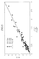
- Figure 1 is a graph of skin-friction ratio and void fraction in a first embodiment.
- Figure 2 is a graph of void fraction and y in a second embodiment.
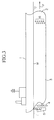
- Figure 3 is an exterior view of a friction-reducing ship in the first embodiment.
- Figure 4 is a schematic block diagram of a control system for gas flow rates to produce bubble jet in the first embodiment.
- Figure 5 is a graph for explaining the basic principle of the first embodiment.
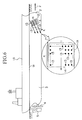
- Figure 6 is an exterior view of a friction-reducing ship in the second embodiment.
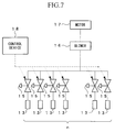
- Figure 7 is a schematic block diagram of a control system for gas supply to produce gas jet in the second embodiment.
- Figure 3 shows a ship 1, the bow 2, submerged surface 3, a screw 4, a rudder 5, jet nozzles 6, the cruising direction F, and the waterline W.
- FIG. 4 shows a block diagram of a gas flow control system comprised by: a motor 7, a blower 8, control valves 9, a gas flow control device 10, and a memory device 11.
- a gas flow control system comprised by: a motor 7, a blower 8, control valves 9, a gas flow control device 10, and a memory device 11.
- Each jet opening 6 is piped to the blower 8 through its own control value 9.
- the blower 8 is operated by the motor 7, and compressed air is supplied through individual control valves 9.
- Each control valve 9 is controlled independently by the gas flow control device 10 to regulate the opening of the control valve 9.
- Gas flow control device 10 includes, among others, an interface circuit to drive the individual control valves 9 and microprocessors to control the interface circuit according to control programs.
- the memory device 11 stores control programs and flow rate control data which are necessary for executing the control programs.
- Flow rate control data include, for example, void fraction distribution data in proximity of the hull surfaces, obtained by computer simulation studies. In other words, the data correlate computed void fraction distribution patterns with the distance (at right angles) to turbulent boundary layers from the various regions of the submerged surface 3.
- control parameters chosen are water speed and gas flow rates to the jet nozzles 6 at the various submerged locations, and the mathematical expressions, relating the void fractions to the distance to turbulent boundary layers for various ranges of these parameters, are stored in the memory device 11. Details of such simulation studies are disclosed in Japanese Patent Application, First Publications H8-144646 and H9-292999, for example.
- the gas flow control device 10 When the ship reaches a cruising speed, for example, the gas flow control device 10 is activated, and jetting of gas bubbles from the jet nozzles 6 is started.
- the gas flow control device 10 receives a signal from the speed control device (not shown) that the ship has reached a cruising speed range, it begins a process of controlling individual control valves 9 according to the control program.
- the gas flow control device 10 After receiving the speed data of the friction-reducing ship as a control parameter from the ship speed control device, the gas flow control device 10 computes the values of the turbulent boundary layer thickness at the bubbly flow velocities for various locations of the submerged surface 3, on the basis of the reported cruising speed and stored shape data for the ship. The gas flow control device 10 then derives a required value of gas flow rate for each of the various locations so that the peak void fraction will occur within the respective boundary layer of the various locations of the submerged surface 3 by entering the values of the thickness of the turbulent boundary layers and the bubbly flow velocities into the gas flow control data.
- the bubbly flow velocities at the various locations of the submerged surface 3 will be different even though the cruising speeds in the various locations may be the same.
- thickness values of the turbulent boundary layers at various locations of the submerged surface 3 are calculated by taking this effect into account, and the gas flow rates to various jet nozzles 6 are adjusted according to such results of computations. For example, if the turbulent boundary layer thickness is different at a waterline W region compared with that at the bottom surface region, gas flow rates to the jet nozzles 6 in the vicinity of the waterline region and the bottom surface region are adjusted independently of the other, so that the peak void fraction distribution will be located within the respective turbulent boundary layer at these locations.
- the bubbly flow velocities at various locations of the submerged surface 3 were obtained from the moving speed of the ship, and the gas flow rates to jet nozzles 6 were adjusted independently, however, it may be simpler to control gas flow rates to the jet nozzles 6 uniformly according to the moving speed, if the thickness of the turbulent boundary layer can be regarded to be not significantly different in the various locations of the submerged surface 3.
- gas flow control data were programmed into the memory device 11, but instead of the memory device 11, an arrangement may be considered in which bubble measuring devices are provided in the rear of the jet nozzles 6 on the submerged surface 3.
- bubble measuring devices may be positioned on both starboard and port sides as well as on the bottom surface.
- such a bubble measuring device may be based on laser scanning of the bubbly water, and the reflection data may be used to determine the number of bubbles in a given volume.
- Figure 6 shows a ship 1A; the bow 2, the submerged surface 3; a screw 4; a rudder 5; the moving direction F; flow lines L; and the waterline W.
- an array (m ⁇ n) of jet nozzles 13, constituted by n lines of nozzles arranged along the flow lines L and m columns of nozzles at right angles to the flow lines L, are disposed on both the port and starboard sides of the ship 1A, although the drawing shows only the starboard side of the ship 1A, a similar m ⁇ n array of jet nozzles 13 are provided on the port side of the submerged surface 3.
- a similar (i ⁇ n) array of jet nozzles, constituted by n lines along the flow lines L and i columns at right angle to the flow lines L, are provided on the bottom section 14 of the ship 1A near the bow 2.
- each jet nozzles 13 arranged along the n lines is connected by pipe to the blower 16 through its own control valve 15.
- the blower 16 is driven by a motor 17 and supplies compressed air to individual nozzles 13 through respective control valve 15.
- a control device 18 controls the opening of the control valve 15.
- compressed air is supplied to a selected number of active nozzles, k, among all the jet nozzles 13 in the array.
- the number of active jet nozzles, k may be comprised by one nozzle 13 or by a plurality of adjacent nozzles 13.
- the radius R of the micro-bubbles produced in the boundary layer between the ship and the water is controlled by the control device 18 selecting a value for the parameter k, the number of active jet nozzles. Therefore, the friction reduction effects can be achieved without being restrained by the ship speed so that optimum bubbly flow fields can be produced at any speeds slower than the cruising speed of the ship. This is a particular important consideration because skin-friction may exert an adverse drag effect on the ship at slower speeds.
- the nozzle arrays were provided on the bottom surface and the side surfaces of the ship 1A, however, the nozzle array may be provided only on the bottom surface or on the side surfaces. In such a case, although the friction reduction effects are not as high, the cost of manufacturing can be lowered.
- the second embodiment thus enables to produce micro-bubbles of certain radius R by blowing gas into the water through a plurality of jet nozzles 13 provided on the hull of the ship 1A, by adjusting the parameter k of active jet nozzles for a given gas flow rate Q and a flow speed U according to expression (2), without being restrained by the ship speed.
Landscapes
- Physics & Mathematics (AREA)
- Fluid Mechanics (AREA)
- Chemical & Material Sciences (AREA)
- Engineering & Computer Science (AREA)
- Combustion & Propulsion (AREA)
- Mechanical Engineering (AREA)
- Ocean & Marine Engineering (AREA)
- Aerodynamic Tests, Hydrodynamic Tests, Wind Tunnels, And Water Tanks (AREA)
- Vehicle Cleaning, Maintenance, Repair, Refitting, And Outriggers (AREA)
- Toys (AREA)
- Cleaning Or Clearing Of The Surface Of Open Water (AREA)
Applications Claiming Priority (6)
| Application Number | Priority Date | Filing Date | Title |
|---|---|---|---|
| JP9208097A JPH1149080A (ja) | 1997-08-01 | 1997-08-01 | 気泡発生方法並びに摩擦低減船及び摩擦低減方法 |
| JP208097/97 | 1997-08-01 | ||
| JP20809797 | 1997-08-01 | ||
| JP32005997 | 1997-11-20 | ||
| JP320059/97 | 1997-11-20 | ||
| JP9320059A JPH11152077A (ja) | 1997-11-20 | 1997-11-20 | 摩擦低減船及び船体の摩擦低減方法 |
Publications (2)
| Publication Number | Publication Date |
|---|---|
| EP0894705A2 true EP0894705A2 (fr) | 1999-02-03 |
| EP0894705A3 EP0894705A3 (fr) | 2000-11-02 |
Family
ID=26516643
Family Applications (1)
| Application Number | Title | Priority Date | Filing Date |
|---|---|---|---|
| EP98401941A Withdrawn EP0894705A3 (fr) | 1997-08-01 | 1998-07-29 | Génération de bulles pour bateau réducteur de friction et méthode pour la réduction de la friction superficielle |
Country Status (9)
| Country | Link |
|---|---|
| US (1) | US6092480A (fr) |
| EP (1) | EP0894705A3 (fr) |
| KR (1) | KR19990023218A (fr) |
| CN (1) | CN1208128A (fr) |
| BR (1) | BR9802815A (fr) |
| CA (1) | CA2242698A1 (fr) |
| FI (1) | FI981669A7 (fr) |
| NO (1) | NO983469L (fr) |
| TW (1) | TW403815B (fr) |
Cited By (3)
| Publication number | Priority date | Publication date | Assignee | Title |
|---|---|---|---|---|
| WO2004012987A3 (fr) * | 2002-04-26 | 2004-06-10 | Regents Board Of | Procede permettant de reduire la trainee visqueuse sur une surface et dispositif de reduction de trainee |
| EP2123551A1 (fr) * | 2008-05-06 | 2009-11-25 | Zuei-Ling Lin | Procédé de réduction de la résistance frictionnelle entre la coque d'un bateau et l'eau en libérant des gaz dans l'eau |
| AU2008202067B2 (en) * | 2008-05-09 | 2014-03-20 | Zuei-Ling Lin | Method of reducing frictional resistance between ship body and water by releasing gases in water |
Families Citing this family (16)
| Publication number | Priority date | Publication date | Assignee | Title |
|---|---|---|---|---|
| US7004094B2 (en) | 2002-06-28 | 2006-02-28 | Carson Dale C | Drag reduction system and method |
| US6932012B1 (en) * | 2004-02-09 | 2005-08-23 | Richard B. Philips | Multi-hull surface vessel with drag reduction on lateral hulls |
| DE102004024343A1 (de) * | 2004-05-17 | 2005-12-22 | New-Logistics Gmbh | Verfahren und Vorrichtung zur Verminderung der Wasserreibung an einem Schiffskörper eines Schiffes |
| US7581508B2 (en) * | 2006-06-29 | 2009-09-01 | Giles David L | Monohull fast ship or semi-planing monohull with a drag reduction method |
| CN105501388A (zh) * | 2008-04-01 | 2016-04-20 | 国立研究开发法人海上技术安全研究所 | 船舶的摩擦阻力减小装置 |
| JP4212640B1 (ja) * | 2008-07-23 | 2009-01-21 | 有限会社ランドエンジニアリング | 摩擦抵抗低減船およびその運転方法 |
| US8327784B2 (en) | 2009-03-23 | 2012-12-11 | Dan Nicolaus Costas | Apparatus for generating and distributing compressed air for reducing drag |
| US7997221B2 (en) * | 2009-03-23 | 2011-08-16 | Dan Nicolaus Costas | Apparatus for reducing drag on a nautical vessel |
| CN101659314A (zh) * | 2009-09-10 | 2010-03-03 | 徐士华 | 船体空泡层的减阻节能与增速方法 |
| US8763547B2 (en) | 2012-07-25 | 2014-07-01 | Dan Nicolaus Costas | Apparatus for lowering drag on a moving nautical vessel |
| JP6555724B2 (ja) * | 2014-06-27 | 2019-08-07 | 国立研究開発法人 海上・港湾・航空技術研究所 | 空気潤滑式船舶の空気供給制御システム及び空気潤滑式船舶 |
| CN106080954A (zh) * | 2016-07-28 | 2016-11-09 | 广船国际有限公司 | 一种船舶电解水微气泡减阻装置 |
| CN106741586B (zh) * | 2016-12-22 | 2019-01-04 | 浙江大学 | 一种船舶水射流约束气泡减阻结构 |
| CN109466687B (zh) * | 2017-09-08 | 2023-09-15 | 中国科学院沈阳自动化研究所 | 一种采用通气空化减阻方法的高速水面艇 |
| US12459603B2 (en) * | 2021-10-27 | 2025-11-04 | Southern Methodist University | Fluid entrapment via perforated surfaces for drag reduction |
| CN120057180A (zh) * | 2025-03-05 | 2025-05-30 | 武汉理工大学 | 一种船舶气泡减阻系统及使用方法 |
Citations (9)
| Publication number | Priority date | Publication date | Assignee | Title |
|---|---|---|---|---|
| JPS5083992A (fr) | 1973-11-27 | 1975-07-07 | ||
| JPS53136289A (en) | 1977-04-30 | 1978-11-28 | Takumi Yoshii | Method of decreasing resistance between solid and liquid utilizing air bubble |
| JPS60139586A (ja) | 1983-12-26 | 1985-07-24 | Ishikawajima Harima Heavy Ind Co Ltd | 船舶の摩擦抵抗減少装置 |
| JPS6139691U (ja) | 1984-08-17 | 1986-03-13 | 三菱重工業株式会社 | 船体摩擦抵抗軽減装置 |
| JPS6171290A (ja) | 1984-09-14 | 1986-04-12 | Yano Denki Seisakusho:Kk | 流体摩擦抵抗減少法 |
| JPS61128185U (fr) | 1985-01-31 | 1986-08-11 | ||
| JPH08144646A (ja) | 1994-11-17 | 1996-06-04 | Tetsuya Inaba | 建築物用引き戸枠 |
| JPH09142818A (ja) | 1995-09-22 | 1997-06-03 | Mitsubishi Chem Corp | カーボンブラック成型体 |
| JPH09292999A (ja) | 1996-04-26 | 1997-11-11 | Nec Corp | クラスタシステムにおけるトランザクション排他方式 |
Family Cites Families (5)
| Publication number | Priority date | Publication date | Assignee | Title |
|---|---|---|---|---|
| US3075489A (en) * | 1960-10-28 | 1963-01-29 | Thompson Ramo Wooldridge Inc | Method and apparatus for reducing drag on submerged vehicles |
| US3455267A (en) * | 1968-01-15 | 1969-07-15 | Augustine J Tucker | System for reducing frictional drag resistance on a ship hull |
| FR2230540A1 (en) * | 1973-01-15 | 1974-12-20 | Fiacre Jean Marie | Method of reducing drag on ships hulls - layer of air around hull is formed from fresh air and air within layer |
| WO1994026583A1 (fr) * | 1993-05-11 | 1994-11-24 | Ishikawajima-Harima Heavy Industries Co., Ltd. | Procede de reduction de la friction sur un navire en deplacement, corps se deplaçant dans l'eau avec friction reduite, procede et appareil de production de microbulles s'appliquant a la reduction de la friction |
| US5803410A (en) * | 1995-12-01 | 1998-09-08 | The United States Of America As Represented By The Administrator Of The National Aeronautics And Space Administration | Skin friction reduction by micro-blowing technique |
-
1998
- 1998-07-06 US US09/110,558 patent/US6092480A/en not_active Expired - Fee Related
- 1998-07-07 TW TW087110991A patent/TW403815B/zh not_active IP Right Cessation
- 1998-07-09 CA CA002242698A patent/CA2242698A1/fr not_active Abandoned
- 1998-07-20 KR KR1019980029148A patent/KR19990023218A/ko not_active Ceased
- 1998-07-28 NO NO983469A patent/NO983469L/no not_active Application Discontinuation
- 1998-07-28 FI FI981669A patent/FI981669A7/fi unknown
- 1998-07-29 EP EP98401941A patent/EP0894705A3/fr not_active Withdrawn
- 1998-07-31 CN CN98116848A patent/CN1208128A/zh active Pending
- 1998-07-31 BR BR9802815-4A patent/BR9802815A/pt not_active Application Discontinuation
Patent Citations (9)
| Publication number | Priority date | Publication date | Assignee | Title |
|---|---|---|---|---|
| JPS5083992A (fr) | 1973-11-27 | 1975-07-07 | ||
| JPS53136289A (en) | 1977-04-30 | 1978-11-28 | Takumi Yoshii | Method of decreasing resistance between solid and liquid utilizing air bubble |
| JPS60139586A (ja) | 1983-12-26 | 1985-07-24 | Ishikawajima Harima Heavy Ind Co Ltd | 船舶の摩擦抵抗減少装置 |
| JPS6139691U (ja) | 1984-08-17 | 1986-03-13 | 三菱重工業株式会社 | 船体摩擦抵抗軽減装置 |
| JPS6171290A (ja) | 1984-09-14 | 1986-04-12 | Yano Denki Seisakusho:Kk | 流体摩擦抵抗減少法 |
| JPS61128185U (fr) | 1985-01-31 | 1986-08-11 | ||
| JPH08144646A (ja) | 1994-11-17 | 1996-06-04 | Tetsuya Inaba | 建築物用引き戸枠 |
| JPH09142818A (ja) | 1995-09-22 | 1997-06-03 | Mitsubishi Chem Corp | カーボンブラック成型体 |
| JPH09292999A (ja) | 1996-04-26 | 1997-11-11 | Nec Corp | クラスタシステムにおけるトランザクション排他方式 |
Cited By (4)
| Publication number | Priority date | Publication date | Assignee | Title |
|---|---|---|---|---|
| WO2004012987A3 (fr) * | 2002-04-26 | 2004-06-10 | Regents Board Of | Procede permettant de reduire la trainee visqueuse sur une surface et dispositif de reduction de trainee |
| US7044073B2 (en) | 2002-04-26 | 2006-05-16 | Board Of Regents Of The University Of Texas System | Methods for reducing the viscous drag on a surface and drag reducing device |
| EP2123551A1 (fr) * | 2008-05-06 | 2009-11-25 | Zuei-Ling Lin | Procédé de réduction de la résistance frictionnelle entre la coque d'un bateau et l'eau en libérant des gaz dans l'eau |
| AU2008202067B2 (en) * | 2008-05-09 | 2014-03-20 | Zuei-Ling Lin | Method of reducing frictional resistance between ship body and water by releasing gases in water |
Also Published As
| Publication number | Publication date |
|---|---|
| NO983469L (no) | 1999-02-02 |
| NO983469D0 (no) | 1998-07-28 |
| EP0894705A3 (fr) | 2000-11-02 |
| BR9802815A (pt) | 1999-11-03 |
| TW403815B (en) | 2000-09-01 |
| FI981669A0 (fi) | 1998-07-28 |
| FI981669L (fi) | 1999-02-02 |
| US6092480A (en) | 2000-07-25 |
| CA2242698A1 (fr) | 1999-02-01 |
| FI981669A7 (fi) | 1999-02-02 |
| KR19990023218A (ko) | 1999-03-25 |
| CN1208128A (zh) | 1999-02-17 |
Similar Documents
| Publication | Publication Date | Title |
|---|---|---|
| US6092480A (en) | Generation of bubbles for friction-reducing ship and method for reducing skin-friction | |
| US5575232A (en) | Method and device for reducing friction on a navigating vehicle | |
| JP5604736B2 (ja) | 船舶の摩擦抵抗低減装置 | |
| EP1305205B1 (fr) | Procede et dispositif pour augmenter l'efficacite et le rendement de techniques de reglage de multiples couches limites | |
| Ma et al. | Influence of scale effect on flow field offset for ships in confined waters | |
| Rogers et al. | Characteristics of a dual-slotted circulation control wing of low aspect ratio intended for naval hydrodynamic applications | |
| Bilandi et al. | Calm-water performance of a boat with two swept steps at high-speeds: Laboratory measurements and mathematical modeling | |
| Chen et al. | Numerical simulation of near-surface turn maneuver of a generic submarine | |
| Ling et al. | Effects of length-to-diameter ratio on a near free surface underwater vehicle | |
| Sindagi et al. | Frictional drag reduction: Review and numerical investigation of microbubble drag reduction in a channel flow | |
| JP2000025683A (ja) | バブレーヤのrancによる弁開度自動制御方法 | |
| Matveev et al. | Air cavity with variable length under a model hull | |
| SG10202104037SA (en) | Air lubrication system of a ship | |
| Tayeb et al. | Optimizing Geometric Parameters of Planing Vessels for Enhanced Hydrodynamic Performance | |
| WO2026029784A1 (fr) | Système et procédé de réduction de traînée sur la coque d'un navire | |
| Thill et al. | Project energy-saving air-lubricated ships (PELS) | |
| Matveev | Static control of drag-reducing air cavities with variable cavitator shape | |
| CN118722947A (zh) | 基于液体射流与超空泡耦合减阻的大潜深水下航行器及其驱动方法 | |
| Ahmed et al. | Numerical prediction of solitary wave formation of a planing hull in shallow water channels | |
| Abramowski | Prediction of propeller forces during ship maneuvering | |
| Jangam et al. | Numerical study on the hydrodynamic performance of integrated interceptor-flap fitted to the transom of a planing vessel | |
| Ghadimi et al. | Impact of aft deformation with wedge and step on performance and stability of high-speed hard chine monohulls via experimental and numerical assessments | |
| Kamal et al. | INFLUENCE OF THE TRANSOM IMMERSION ON SHIP RESISTANCE COMPONENTS AT LOW AND MEDIUM SPEEDS. | |
| JPH11152077A (ja) | 摩擦低減船及び船体の摩擦低減方法 | |
| KR19990036946A (ko) | 선체의 기포 피복 상태의 시뮬레이션 방법 및장치, 그리고 시뮬레이션 프로그램이 기억된 컴퓨터에 의해 독취가능한 기억 매체 |
Legal Events
| Date | Code | Title | Description |
|---|---|---|---|
| PUAI | Public reference made under article 153(3) epc to a published international application that has entered the european phase |
Free format text: ORIGINAL CODE: 0009012 |
|
| AK | Designated contracting states |
Kind code of ref document: A2 Designated state(s): AT BE CH CY DE DK ES FI FR GB GR IE IT LI LU MC NL PT SE |
|
| AX | Request for extension of the european patent |
Free format text: AL;LT;LV;MK;RO;SI |
|
| PUAL | Search report despatched |
Free format text: ORIGINAL CODE: 0009013 |
|
| AK | Designated contracting states |
Kind code of ref document: A3 Designated state(s): AT BE CH CY DE DK ES FI FR GB GR IE IT LI LU MC NL PT SE |
|
| AX | Request for extension of the european patent |
Free format text: AL;LT;LV;MK;RO;SI |
|
| AKX | Designation fees paid | ||
| REG | Reference to a national code |
Ref country code: DE Ref legal event code: 8566 |
|
| STAA | Information on the status of an ep patent application or granted ep patent |
Free format text: STATUS: THE APPLICATION IS DEEMED TO BE WITHDRAWN |
|
| 18D | Application deemed to be withdrawn |
Effective date: 20010503 |