EP0894982A2 - Dispositif asservi hydraulique - Google Patents
Dispositif asservi hydraulique Download PDFInfo
- Publication number
- EP0894982A2 EP0894982A2 EP98114115A EP98114115A EP0894982A2 EP 0894982 A2 EP0894982 A2 EP 0894982A2 EP 98114115 A EP98114115 A EP 98114115A EP 98114115 A EP98114115 A EP 98114115A EP 0894982 A2 EP0894982 A2 EP 0894982A2
- Authority
- EP
- European Patent Office
- Prior art keywords
- cylinder
- piston
- communication
- oil
- pilot shaft
- Prior art date
- Legal status (The legal status is an assumption and is not a legal conclusion. Google has not performed a legal analysis and makes no representation as to the accuracy of the status listed.)
- Granted
Links
Images


Classifications
-
- F—MECHANICAL ENGINEERING; LIGHTING; HEATING; WEAPONS; BLASTING
- F15—FLUID-PRESSURE ACTUATORS; HYDRAULICS OR PNEUMATICS IN GENERAL
- F15B—SYSTEMS ACTING BY MEANS OF FLUIDS IN GENERAL; FLUID-PRESSURE ACTUATORS, e.g. SERVOMOTORS; DETAILS OF FLUID-PRESSURE SYSTEMS, NOT OTHERWISE PROVIDED FOR
- F15B21/00—Common features of fluid actuator systems; Fluid-pressure actuator systems or details thereof, not covered by any other group of this subclass
- F15B21/04—Special measures taken in connection with the properties of the fluid
- F15B21/044—Removal or measurement of undissolved gas, e.g. de-aeration, venting or bleeding
-
- F—MECHANICAL ENGINEERING; LIGHTING; HEATING; WEAPONS; BLASTING
- F15—FLUID-PRESSURE ACTUATORS; HYDRAULICS OR PNEUMATICS IN GENERAL
- F15B—SYSTEMS ACTING BY MEANS OF FLUIDS IN GENERAL; FLUID-PRESSURE ACTUATORS, e.g. SERVOMOTORS; DETAILS OF FLUID-PRESSURE SYSTEMS, NOT OTHERWISE PROVIDED FOR
- F15B11/00—Servomotor systems without provision for follow-up action; Circuits therefor
- F15B11/08—Servomotor systems without provision for follow-up action; Circuits therefor with only one servomotor
- F15B11/12—Servomotor systems without provision for follow-up action; Circuits therefor with only one servomotor providing distinct intermediate positions; with step-by-step action
- F15B11/121—Servomotor systems without provision for follow-up action; Circuits therefor with only one servomotor providing distinct intermediate positions; with step-by-step action providing distinct intermediate positions
-
- F—MECHANICAL ENGINEERING; LIGHTING; HEATING; WEAPONS; BLASTING
- F15—FLUID-PRESSURE ACTUATORS; HYDRAULICS OR PNEUMATICS IN GENERAL
- F15B—SYSTEMS ACTING BY MEANS OF FLUIDS IN GENERAL; FLUID-PRESSURE ACTUATORS, e.g. SERVOMOTORS; DETAILS OF FLUID-PRESSURE SYSTEMS, NOT OTHERWISE PROVIDED FOR
- F15B9/00—Servomotors with follow-up action, e.g. obtained by feed-back control, i.e. in which the position of the actuated member conforms with that of the controlling member
- F15B9/02—Servomotors with follow-up action, e.g. obtained by feed-back control, i.e. in which the position of the actuated member conforms with that of the controlling member with servomotors of the reciprocatable or oscillatable type
- F15B9/08—Servomotors with follow-up action, e.g. obtained by feed-back control, i.e. in which the position of the actuated member conforms with that of the controlling member with servomotors of the reciprocatable or oscillatable type controlled by valves affecting the fluid feed or the fluid outlet of the servomotor
- F15B9/10—Servomotors with follow-up action, e.g. obtained by feed-back control, i.e. in which the position of the actuated member conforms with that of the controlling member with servomotors of the reciprocatable or oscillatable type controlled by valves affecting the fluid feed or the fluid outlet of the servomotor in which the controlling element and the servomotor each controls a separate member, these members influencing different fluid passages or the same passage
Definitions
- the present invention relates to a hydraulic servo device for converting a small-torque angular displacement into a large-load linear displacement, and more particularly to a hydraulic servo device for use in controlling the operation of a scoop tube as a speed control mechanism for a variable-speed fluid coupling.
- Figure 11 shows an actuator for a water feeding device for supplying water to a high-capacity boiler.
- the rotation of an input shaft 121 is accelerated and transmitted through a large-diameter gear 122 and a small-diameter gear 124 to a drive shaft 123, from which the rotation is transmitted through a fluid coupling C to a driven shaft 125.
- the rotation is then accelerated and transmitted from the driven shaft 125 through a large-diameter gear 131 and a small-diameter gear 133 to an output shaft 132.
- the fluid coupling C comprises an impeller 126 and an impeller casing 128 which are mounted on the drive shaft 123, and a runner 127 mounted on the driven shaft 125.
- a scoop tube 130 for regulating the rate of the working oil is disposed in the working chamber.
- the torque transmitted by the fluid coupling C can be controlled by moving the scoop tube 130 into and out of the working chamber.
- the fluid coupling C which is of a simple structure, is capable of continuously changing the rotational speed of the load side shaft (output shaft) from a minimum level to a maximum level.
- the scoop tube needs to resist against forces applied by the working oil thereby to be positioned accurately.
- One actuating device for the scoop tube comprises, for example, a hydraulic servo device for amplifying and transmitting a displacement produced under a small force by an electric actuator, as disclosed in Japanese laid-open patent publication No. 7-208499, for example.
- the disclosed hydraulic servo device has a piston slidably mounted on a pilot shaft disposed in a cylinder, with oil passages defined in a surface of the pilot shaft and inside the piston. A rotation of the pilot shaft is converted into a displacement of the piston, which is outputted from the hydraulic servo device.
- the scoop tube is positionally controlled under feedback control based on a signal from a displacement sensor located in a predetermined position.
- the pilot shaft needs to be reduced in diameter. If the diameter of the pilot shaft is reduced, however, the width of the oil passage defined as a groove in the surface of the pilot shaft is also reduced. When the rotational speed of the pilot shaft is increased, the oil passage in the surface of the pilot shaft is displaced out of alignment in the oil passage in the piston, tending to cause a control failure. Consequently, the control response of the hydraulic servo device is limited.
- a hydraulic servo device comprising a cylinder, a pilot shaft disposed angularly movably and extending axially in the cylinder, the pilot shaft having a pair of communication passages defined in an outer circumferential surface thereof, a piston movably mounted on the pilot shaft for axial movement in the cylinder, the piston having a pair of oil passages defined therein, and an actuator for angularly moving the pilot shaft about its own axis to bring at least one of the communication passages into communication with at least one of the oil passages to apply a fluid under pressure to the piston for axially moving the piston in the cylinder.
- the communication passages and the oil passages are relatively small in diameter and width, and can be held in communication with each other in a relatively large angular range of the pilot shaft, so that the hydraulic servo device can be controlled with a high response.
- the communication passages and the oil passages are relatively positioned such that the communication passages and the oil passages are brought into communication with each other in different angular ranges of the pilot shaft.
- Each of the communication passages is angularly nonlinear in a configuration thereof.
- the oil passages include an oil supply passage for supplying a working oil under pressure and an oil drain passage connected to a drain.
- a hydraulic servo device comprising a cylinder, a pilot shaft disposed angularly movably and extending axially in the cylinder, the pilot shaft having a communication passage defined in an outer circumferential surface thereof, a piston movably mounted on the pilot shaft for axial movement in the cylinder, the piston having an oil passage defined therein, an actuator for angularly moving the pilot shaft about its own axis to bring the communication passage into communication with the oil passage to apply a fluid under pressure to the piston for axially moving the piston in the cylinder, the cylinder having an interior space compartmented by the piston into a first space communicating with a pressurized oil hole and a second space which can selectively be brought into and out of communication with the oil passage by the communication passage, and an air bleeder pipe connected to an upper region of the cylinder in communication with the second space. Highly compressible air which has been trapped in the second space can be discharged through the air bleeder pipe for thereby allowing the hydraulic servo device
- the air bleeder pipe has an orifice and vented to the atmosphere therethrough.
- the air bleeder pipe has a check valve and vented to the atmosphere therethrough.
- a hydraulic servo device comprising a cylinder, a pilot shaft disposed angularly movably and extending axially in the cylinder, the pilot shaft having a communication passage defined in an outer circumferential surface thereof, a piston movably mounted on the pilot shaft for axial movement in the cylinder, the piston having an oil passage defined therein, and an actuator for angularly moving the pilot shaft about its own axis to bring the communication passage into communication with the oil passage to apply a fluid under pressure to the piston for axially moving the piston in the cylinder, the cylinder having an interior space compartmented by the piston into a first space communicating with a pressurized oil hole and a second space which can selectively be brought into and out of communication with the oil passage by the communication passage, the cylinder having a recess for collecting particles therein, the recess being defined in a lower region of an inner cylindrical surface thereof respectively in the first space and/or the second space. Since particles produced upon sliding movement of the piston
- the cylinder has a discharge hole defined in a cylindrical wall thereof for discharging particles collected in the recess.
- a hydraulic servo device comprising a cylinder, a pilot shaft disposed angularly movably and extending axially in the cylinder, the pilot shaft having a communication passage defined in an outer circumferential surface thereof, a piston movably mounted on the pilot shaft for axial movement in the cylinder, the piston having an oil passage defined therein, an actuator for angularly moving the pilot shaft about its own axis to bring the communication passage into communication with the oil passage to apply a fluid under pressure to the piston for axially moving the piston in the cylinder, the cylinder having an interior space compartmented by the piston into a first space communicating with a pressurized oil hole and a second space which can selectively be brought into and out of communication with the oil passage by the communication passage, and an oil reservoir disposed in covering relation to an end wall of the cylinder which defines the first space.
- a hydraulic servo device comprising a cylinder, a pilot shaft disposed angularly movably and extending axially in the cylinder, the pilot shaft having a communication passage defined in an outer circumferential surface thereof, a piston movably mounted on the pilot shaft for axial movement in the cylinder, the piston having an oil passage defined therein, and an actuator for angularly moving the pilot shaft about its own axis to bring the communication passage into communication with the oil passage to apply a fluid under pressure to the piston for axially moving the piston in the cylinder, the piston having engaging means on an end face thereof for engaging a piston remover for pulling out the piston from the cylinder.
- the piston can easily be removed from the cylinder by the piston remover which is engaged by the engaging means on the piston.
- the piston, the cylinder, and a scoop tube mounted on the piston can easily be inspected, service, for maintenance, or can easily be replaced.
- a fluid coupling comprising an impeller and an impeller casing which are adapted to be mounted on a drive shaft, the impeller casing defining a working chamber therein, a runner adapted to be mounted on a driven shaft, a scoop tube disposed for movement into and out of the working chamber for generating the rate of a working oil introduced into the working chamber, and any of the hydraulic servo devices described above for positionally controlling the scoop tube.
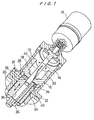
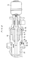
- a hydraulic servo device which is typically used as an actuating device for the scoop tube of the fluid coupling shown in Figure 11, comprises a cylinder 10 as a pressure casing, a pilot actuating device 12 mounted on a proximal end of the cylinder 10 and connected to a controller (not shown), a pilot shaft 14 projecting from the pilot actuating device 12 into the cylinder 10, and a piston 16 disposed in a space defined between the cylinder 10 and the pilot shaft 14.
- the piston 16 is slidably movable axially along the pilot shaft 14, but is prevented from rotating around the pilot shaft 14.
- the piston 16 comprises a large-diameter portion 18 closer to the proximal end of the cylinder 10 and a small-diameter portion 20 closer to the distal end of the cylinder 10.
- the small-diameter portion 20 projects axially out of the cylinder 10 through a slide hole 24 that is defined in an end wall 22 on the distal end of the cylinder 10.
- the small-diameter portion 20 supports on its projecting end an attachment portion 26 for supporting the scoop tube that is to be actuated by the hydraulic servo device.
- the piston 16 compartments the space within the cylinder 10 into a first space 28 defined around the small-diameter portion 20 and a second space 30 defined in and on the free end of the large-diameter portion 18.
- a pressurized oil passageway 32 is defined radially in the distal end of the cylinder 10 in communication with the first space 28.
- the cylinder 10 has an annular step 34 on an inner cylindrical wall thereof which serves as a stop for defining a stop position for the piston 16 on its axial movement towards the distal end of the cylinder 10. With the cylinder 10 being held in the stop position, the first space 28 is still maintained in the distal end of the cylinder 10 while being kept in communication with the first space 28.
- the small-diameter portion 20 of the piston 16 has an axial central hole 36 defined therein which receives the pilot shaft 14 slidably therein, and a pair of oil supply passages 38a, 38b defined radially therein near the large-diameter portion 18 and extending from the first space 28 into the axial central hole 36.
- the oil supply passages 38a, 38b are positioned substantially symmetrically with respect to the central axis of the small-diameter portion 20.
- the small-diameter portion 20 also has a pair of oil drain passages 40a, 40b defined therein substantially symmetrically with respect to a plane passing through the central axis of the small-diameter portion 20 parallel to the oil supply passages 38a, 38b.
- the oil drain passages 40a, 40b are open at the attachment portion 26.
- the axial central hole 36 and the oil drain passages 40a, 40b are both connected to an external drain (not shown).
- the pilot shaft 14 has a pair of communication passages 42a, 42b defined in an outer circumferential surface thereof for providing communication between the oil supply passages 38a, 38b and the second space 30 depending upon angular location of the pilot shaft 14.
- the communication passages 42a, 42b are positioned substantially symmetrically with respect to the central axis of the pilot shaft 14.
- Each of the communication passages 42a, 42b extends substantially axially over a length which corresponds to the stroke of the piston 16, and also extends helically circumferentially over a substantially half the full circumference of the pilot shaft 14.
- the oil supply passages 38a, 38b and the oil drain passages 40a, 40b have a diameter equal to the width of the communication passages 42a, 42b.
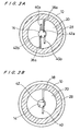
- one of the oil supply passages 38a, 38b is shown as an oil supply passage 38, one of the oil drain passages 40a, 40b as an oil drain passage 40, and one of the communication passages 42a, 42b as a communication passage 42.
- the piston 16 has a pressure bearing area in the first space 28 which is represented by the difference between the cross-sectional area of the large-diameter portion 18 and the cross-sectional area of the small-diameter portion 20.
- the piston 16 has a pressure bearing area in the second space 30 which is represented by the difference between the cross-sectional area of the large-diameter portion 18 and the cross-sectional area of the pilot shaft 14. Therefore, the pressure bearing area of the piston 16 in the second space 30 is greater than the pressure bearing area of the piston 16 in the first space 28.
- each of the communication passages 42 is angularly nonlinear in its configuration for thereby allowing the piston 16 to move axially through a linear stroke in response to an angular displacement of the pilot shaft 14.
- the large-diameter portion 18 of the piston 16 is hollow so that, even when the piston 16 is axially displaced fully to the proximal end of the cylinder 10, the communication passages 42 are not covered by the piston 16.
- the oil supply passage 38a and the oil drain passage 40a adjacent thereto are spaced more closely from each other than the oil supply passage 38b and the oil drain passage 40b adjacent thereto are spaced from each other.
- This angular positional relationship between these passages 38a, 40a and 38b, 40b ensures that when the pilot shaft 14 is angularly moved about its own axis, the communication passage 42a starts to overlap or communicate with the oil supply passage 38a or the oil drain passage 40a earlier than the communication passage 42b starts to overlap or communicate with the oil supply passage 38b or the oil drain passage 40b.
- the communication passage 42a overlaps or communicates with the oil supply passage 38a or the oil drain passage 40a when the pilot shaft 14 is angularly moved about its own axis through an angular range 2 ⁇ where ⁇ corresponds to the diameter of the passages 38a, 38b, 40a, 40b and hence the width of the passages 42a, 42b.
- the angular range 2 ⁇ through which the pilot shaft 14 is angularly moved about its own axis when the communication passage 42b overlaps or communicates with the oil supply passage 38b or the oil drain passage 40b is delayed by an angle ⁇ which is not in excess of the angle ⁇ .
- the overall angle range through which the pilot shaft 14 is angularly moved about its own axis when the communication passages 42a, 42b overlap or communicate with the oil supply passages 38a, 38b or the oil drain passages 40a, 40b is represented by (2 ⁇ + ⁇ ).
- This overall angular range (2 ⁇ + ⁇ ) is greater than the angular range through which the pilot shaft 14 is angularly moved about its own axis when a communication passage 42 overlaps or communicates with one oil supply passage 38 or one oil drain passage 40 in the conventional hydraulic servo device as shown in Figure 3B.
- a working oil starts to be introduced under pressure from the first space 28 through the oil supply passage 38a and the communication passage 42a into the second space 30, and the piston 16 is axially displaced towards the distal end of the cylinder 10 due to the pressure area difference on both directions of the piston 16. Since the communication passage 42a is inclined with respect to the ridge line of the pilot shaft 14, when the piston 16 is axially displaced towards the distal end of the cylinder 10, the communication passage 42a is again brought out of communication with the oil supply passage 38a as shown in Figure 2A so that the axial displacement of the piston 16 is stopped.
- the controller issues a control signal to the pilot actuating device 12 which angularly moves the pilot shaft 14 further clockwise into the position shown in Figure 3A.
- both the communication passages 42a, 42b communicate with the oil supply passages 38a, 38b, respectively, allowing the working oil to flow under pressure from the first space 28 through the oil supply passages 38a, 38b and the communication passages 42a, 42b into the second space 30.
- the piston 16 is axially displaced by an increased working oil flow rate to produce an increased drive power with an increased response.
- the communication passages 42a, 42b are less liable to be brought out of communication with the oil supply passages 38a, 38b because the angular range of the pilot shaft 14 in which the communication passages 42a, 42b communicate with the oil supply passages 38a, 38b is larger than when only one communication passage 42 and one oil supply passage 38 are provided.
- the pilot shaft 14 For axially moving the piston 16 towards the proximal end of the cylinder 10, the pilot shaft 14 is angularly moved from the position shown in Figure 2A counterclockwise in the direction opposite to the direction indicated by the arrow in Figure 2B.
- the communication passage 42a starts to communicate with the oil drain passage 40a, connecting the second space 30 to the drain. Since the oil pressure in the second space 30 drops, the piston 16 is axially displaced towards the proximal end of the cylinder 10 under the oil pressure in the first space 28 until the communication passage 42a is brought out of communication with the oil drain passage 40a as shown in Figure 2A.
- the pilot shaft 14 is continuously angularly moved under feedback control while the axial position of the piston 16 is being detected, for thereby controlling the axial position of the piston 16.
- the piston 16 is axially displaced towards the proximal end of the cylinder 10 with an increased response and without the danger of the communication passages 42a, 42b being brought out of communication with the oil drain passages 40a, 40b.
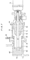
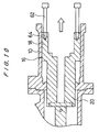
- Figure 6 shows a hydraulic servo device according to a second embodiment of the present invention.
- an air bleeder pipe 44 is connected at an upper region of the proximal end of the cylinder 10 in communication with the second space 30.
- the air bleeder pipe 44 is vented to the atmosphere through an orifice 46. Air contained in the working oil flowing from the pressurized oil passageway 32 and trapped in the second space 30 can be discharged through the air bleeder pipe 44. Therefore, the response of the hydraulic servo device is prevented from being adversely affected by such trapped air. Since the orifice 46 has a small air passage hole, it can discharge the trapped air while keeping the oil pressure in the second space 30.
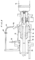
- FIG. 7 shows a hydraulic servo device according to a third embodiment of the present invention.
- the hydraulic servo device shown in Figure 7 is an improvement in the hydraulic servo device shown in Figure 6.
- the air bleeder pipe 44 vented to the atmosphere by the orifice 46 is connected to the upper region of the proximal end of the cylinder 10, and the slide hole 24 in the end wall 22 is covered with an oil reservoir 48.
- the oil reservoir 48 is defined by a bottom plate 50 and a wall 52 which are attached to the end wall 22.
- the wall 52 has a hole (not shown) defined therein for the passage therethrough of the scoop tube that is to be actuated by the hydraulic servo device.
- the oil reservoir 48 has a height which is preferably the same as or greater than the height of the lower end of the air bleeder pipe 44 that is connected to the cylinder 10.
- the oil reservoir 48 covering the slide hole 24 is effective to prevent the working oil from seeping from the second space 30 through the gap between the small-diameter portion 20 and the end wall 22, so that the hydraulic servo device can start to operate stably or with desired response.
- Figure 8 shows a hydraulic servo device according to a fourth embodiment of the present invention.
- the hydraulic servo device shown in Figure 8 is also an improvement in the hydraulic servo device shown in Figure 6.
- the air bleeder pipe 44 has a check valve 50 connected between its end coupled to the cylinder 10 and the orifice 46.
- the check valve 50 serves to prevent air from flowing into the second space 30 through the air bleeder pipe 44 while the hydraulic servo device is at rest.
- the check valve 50 may be replaced with a remotely controlled or automatically operated on-off valve, which can be open only when necessary.
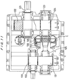
- FIG. 9 shows a hydraulic servo device according to a fifth embodiment of the present invention.
- two recesses 56 are defined in lower regions of an inner cylindrical surface of the cylinder 10 respectively in the first and second spaces 28, 30 near the distal and proximal ends of the cylinder 10.
- the recesses 56 serve to collect particles that are produced as the piston 16 slides against the inner cylindrical surface of the cylinder 10.
- the cylinder 10 also has two discharge holes 58 defined in its cylindrical wall in communication with the bottoms of the respective recesses 56, for discharging particles P collected on the bottoms of the respective recesses 56.
- the discharge holes 58 are normally closed by respective pressure-tight plugs 60.
- Figure 10 shows a hydraulic servo device according to a sixth embodiment of the present invention.
- the hydraulic servo device shown in Figure 10 is designed for easy maintenance.
- the large-diameter portion 18 of the piston 16 has threaded holes 64 defined in an end face thereof, and elongate bolts 62 are threaded in the respective threaded holes 64 as piston removers for pulling the piston 10 out of the cylinder 10.
- an end wall is detached from the proximal end of the cylinder 10, and the pilot shaft 14 is removed.
- the elongate bolts 62 are threaded into the respective threaded holes 64, and axially drawn to pull out the piston 16 from the cylinder 10.
- the elongate bolts 62 can remove the piston 16 from the cylinder 10 without disassembling the cylinder 10, so that the worker can easily inspect and service the piston 16, the cylinder 10, the scoop tube mounted on the piston 16 for maintenance, or easily replace them.
- the invention relates to a hydraulic servo device comprising: a cylinder; a pilot shaft, said pilot shaft having a pair of communication passages; and a piston movably mounted on said pilot shaft for axial movement in said cylinder.
Landscapes
- Engineering & Computer Science (AREA)
- Physics & Mathematics (AREA)
- Fluid Mechanics (AREA)
- Mechanical Engineering (AREA)
- General Engineering & Computer Science (AREA)
- Chemical & Material Sciences (AREA)
- Analytical Chemistry (AREA)
- Actuator (AREA)
Applications Claiming Priority (3)
| Application Number | Priority Date | Filing Date | Title |
|---|---|---|---|
| JP218003/97 | 1997-07-29 | ||
| JP21800397A JP3494858B2 (ja) | 1997-07-29 | 1997-07-29 | 油圧サーボ装置 |
| JP21800397 | 1997-07-29 |
Publications (3)
| Publication Number | Publication Date |
|---|---|
| EP0894982A2 true EP0894982A2 (fr) | 1999-02-03 |
| EP0894982A3 EP0894982A3 (fr) | 2000-05-24 |
| EP0894982B1 EP0894982B1 (fr) | 2004-01-07 |
Family
ID=16713111
Family Applications (1)
| Application Number | Title | Priority Date | Filing Date |
|---|---|---|---|
| EP98114115A Expired - Lifetime EP0894982B1 (fr) | 1997-07-29 | 1998-07-28 | Dispositif asservi hydraulique |
Country Status (4)
| Country | Link |
|---|---|
| EP (1) | EP0894982B1 (fr) |
| JP (1) | JP3494858B2 (fr) |
| CN (1) | CN1124418C (fr) |
| DE (1) | DE69820934T2 (fr) |
Cited By (3)
| Publication number | Priority date | Publication date | Assignee | Title |
|---|---|---|---|---|
| CN102016383B (zh) * | 2008-02-29 | 2013-06-05 | Cbe环球控股公司 | 围绕基准轴旋转而移动物体的系统和方法 |
| EP2853754A1 (fr) * | 2013-08-21 | 2015-04-01 | Airbus Operations Limited | Agencement d'actionneur hydraulique |
| CN119755174A (zh) * | 2025-03-06 | 2025-04-04 | 长春一东汽车零部件制造有限责任公司 | 一种电动伺服液压缸 |
Families Citing this family (4)
| Publication number | Priority date | Publication date | Assignee | Title |
|---|---|---|---|---|
| US7249458B2 (en) * | 2005-07-22 | 2007-07-31 | Ashradn Holdings Ltd. | Self-contained hydraulic actuator system |
| MA33106B1 (fr) * | 2009-02-10 | 2012-03-01 | Cbe Global Holdings Inc | Systeme d'actionneur non lineaire et procede associe |
| CN103029828B (zh) * | 2012-12-11 | 2016-03-23 | 江西洪都航空工业集团有限责任公司 | 一种机械式旋转作动器 |
| KR101888053B1 (ko) * | 2016-12-02 | 2018-08-13 | 한국남부발전(주) | 스쿠프튜브 유압조절장치를 구비한 대용량 변속 유체 커플링 |
Family Cites Families (9)
| Publication number | Priority date | Publication date | Assignee | Title |
|---|---|---|---|---|
| US2874542A (en) * | 1943-04-21 | 1959-02-24 | Sperry Rand Corp | Motion reproducing mechanism |
| GB693504A (en) * | 1949-07-25 | 1953-07-01 | Boulton Aircraft Ltd | Improvements in and relating to servo systems |
| US2926635A (en) * | 1957-12-24 | 1960-03-01 | Clark Equipment Co | Power shifting mechanism |
| US3757640A (en) * | 1971-12-01 | 1973-09-11 | Avco Corp | Simplified follower servomechanism |
| US4245547A (en) * | 1977-10-31 | 1981-01-20 | Commercial Shearing, Inc. | Rotary to linear servo mechanisms |
| DE3374578D1 (en) * | 1982-02-26 | 1987-12-23 | Parisienne Outillage | Hydraulic directional spool valve |
| JPS60256603A (ja) * | 1984-06-01 | 1985-12-18 | Yukio Watanabe | シリンダ装置 |
| JPH0729313Y2 (ja) * | 1990-10-18 | 1995-07-05 | 株式会社大金製作所 | プルタイプクラッチ用レリーズ装置 |
| DE19537417C2 (de) * | 1995-10-07 | 1997-07-24 | Eurocopter Deutschland | Hydraulischer Stellantrieb |
-
1997
- 1997-07-29 JP JP21800397A patent/JP3494858B2/ja not_active Expired - Lifetime
-
1998
- 1998-07-28 EP EP98114115A patent/EP0894982B1/fr not_active Expired - Lifetime
- 1998-07-28 DE DE69820934T patent/DE69820934T2/de not_active Expired - Lifetime
- 1998-07-29 CN CN98103096.3A patent/CN1124418C/zh not_active Expired - Lifetime
Cited By (3)
| Publication number | Priority date | Publication date | Assignee | Title |
|---|---|---|---|---|
| CN102016383B (zh) * | 2008-02-29 | 2013-06-05 | Cbe环球控股公司 | 围绕基准轴旋转而移动物体的系统和方法 |
| EP2853754A1 (fr) * | 2013-08-21 | 2015-04-01 | Airbus Operations Limited | Agencement d'actionneur hydraulique |
| CN119755174A (zh) * | 2025-03-06 | 2025-04-04 | 长春一东汽车零部件制造有限责任公司 | 一种电动伺服液压缸 |
Also Published As
| Publication number | Publication date |
|---|---|
| JP3494858B2 (ja) | 2004-02-09 |
| EP0894982B1 (fr) | 2004-01-07 |
| EP0894982A3 (fr) | 2000-05-24 |
| JPH1144303A (ja) | 1999-02-16 |
| DE69820934D1 (de) | 2004-02-12 |
| DE69820934T2 (de) | 2004-11-04 |
| CN1124418C (zh) | 2003-10-15 |
| CN1210208A (zh) | 1999-03-10 |
Similar Documents
| Publication | Publication Date | Title |
|---|---|---|
| KR100497822B1 (ko) | 수압작동시스템 | |
| US9989056B2 (en) | Hydraulic pump with integrated clutch | |
| EP0894982B1 (fr) | Dispositif asservi hydraulique | |
| US4860646A (en) | Compactor with hydraulic dwell and method | |
| JP3419591B2 (ja) | 制御可能な打撃数および打撃エネルギーを有する液圧打撃装置 | |
| JPH08511327A (ja) | 特に急速閉鎖弁用のサーボモータ | |
| US5201842A (en) | Coupling with a hydraulically pressurized hub | |
| EP0797020A1 (fr) | Dispositif de frein pour moteur hydraulique | |
| US5960892A (en) | Automatically driven pile driver drilling device | |
| US8661925B2 (en) | Hydraulically operated shifter for power take-off | |
| EP0481692A2 (fr) | Dispositif à axes multiples | |
| US6332477B1 (en) | Piston-type accumulator for a hydraulic fluid to be supplied to a consumer in a hydraulic installation | |
| CN100436073C (zh) | 液压冲击装置 | |
| US5664417A (en) | Control valve for prime mover speed control in hydraulic systems | |
| US3550507A (en) | Hydraulic valve | |
| WO2021070828A1 (fr) | Dispositif d'entraînement hydraulique | |
| US4452125A (en) | Manual-hydraulic actuator | |
| SE502257C2 (sv) | Plungeventil | |
| EP1077096B1 (fr) | Dispositif de pose des éléments de fixation à deux pièces | |
| CN114811057A (zh) | 阀驱动装置、用于运行阀驱动装置的方法和过程装置 | |
| EP0227296B1 (fr) | Commande programmée de débit liée à la pression pour valve hydraulique | |
| US6189444B1 (en) | Press having a dosing system | |
| NO803601L (no) | Sperreinnretning for girtransmisjon, spesielt for biler | |
| SE1050170A1 (sv) | Arrangemang samt förfarande för styrning av en kolvrörelse | |
| WO1992008896A1 (fr) | Servo-mecanisme autonome pour mouvements de levage monte sur un arbre en rotation |
Legal Events
| Date | Code | Title | Description |
|---|---|---|---|
| PUAI | Public reference made under article 153(3) epc to a published international application that has entered the european phase |
Free format text: ORIGINAL CODE: 0009012 |
|
| AK | Designated contracting states |
Kind code of ref document: A2 Designated state(s): DE GB IT |
|
| AX | Request for extension of the european patent |
Free format text: AL;LT;LV;MK;RO;SI |
|
| RIC1 | Information provided on ipc code assigned before grant |
Free format text: 7F 15B 9/10 A, 7F 15B 21/04 B, 7F 15B 11/12 B |
|
| PUAL | Search report despatched |
Free format text: ORIGINAL CODE: 0009013 |
|
| AK | Designated contracting states |
Kind code of ref document: A3 Designated state(s): AT BE CH CY DE DK ES FI FR GB GR IE IT LI LU MC NL PT SE |
|
| AX | Request for extension of the european patent |
Free format text: AL;LT;LV;MK;RO;SI |
|
| 17P | Request for examination filed |
Effective date: 20001121 |
|
| AKX | Designation fees paid |
Free format text: DE GB IT |
|
| 17Q | First examination report despatched |
Effective date: 20020517 |
|
| GRAH | Despatch of communication of intention to grant a patent |
Free format text: ORIGINAL CODE: EPIDOS IGRA |
|
| GRAS | Grant fee paid |
Free format text: ORIGINAL CODE: EPIDOSNIGR3 |
|
| GRAA | (expected) grant |
Free format text: ORIGINAL CODE: 0009210 |
|
| AK | Designated contracting states |
Kind code of ref document: B1 Designated state(s): DE GB IT |
|
| REG | Reference to a national code |
Ref country code: GB Ref legal event code: FG4D |
|
| REF | Corresponds to: |
Ref document number: 69820934 Country of ref document: DE Date of ref document: 20040212 Kind code of ref document: P |
|
| PLBE | No opposition filed within time limit |
Free format text: ORIGINAL CODE: 0009261 |
|
| STAA | Information on the status of an ep patent application or granted ep patent |
Free format text: STATUS: NO OPPOSITION FILED WITHIN TIME LIMIT |
|
| 26N | No opposition filed |
Effective date: 20041008 |
|
| PGFP | Annual fee paid to national office [announced via postgrant information from national office to epo] |
Ref country code: IT Payment date: 20080729 Year of fee payment: 11 |
|
| PG25 | Lapsed in a contracting state [announced via postgrant information from national office to epo] |
Ref country code: IT Free format text: LAPSE BECAUSE OF NON-PAYMENT OF DUE FEES Effective date: 20090728 |
|
| PGFP | Annual fee paid to national office [announced via postgrant information from national office to epo] |
Ref country code: GB Payment date: 20170726 Year of fee payment: 20 Ref country code: DE Payment date: 20170725 Year of fee payment: 20 |
|
| REG | Reference to a national code |
Ref country code: DE Ref legal event code: R071 Ref document number: 69820934 Country of ref document: DE |
|
| REG | Reference to a national code |
Ref country code: GB Ref legal event code: PE20 Expiry date: 20180727 |
|
| PG25 | Lapsed in a contracting state [announced via postgrant information from national office to epo] |
Ref country code: GB Free format text: LAPSE BECAUSE OF EXPIRATION OF PROTECTION Effective date: 20180727 |