EP0895116A2 - Farbselektive Flüssigkristall-Lichtventile mit reflektierenden Polarizatoren - Google Patents
Farbselektive Flüssigkristall-Lichtventile mit reflektierenden Polarizatoren Download PDFInfo
- Publication number
- EP0895116A2 EP0895116A2 EP98305983A EP98305983A EP0895116A2 EP 0895116 A2 EP0895116 A2 EP 0895116A2 EP 98305983 A EP98305983 A EP 98305983A EP 98305983 A EP98305983 A EP 98305983A EP 0895116 A2 EP0895116 A2 EP 0895116A2
- Authority
- EP
- European Patent Office
- Prior art keywords
- polarizer
- color shutter
- reflecting
- light
- color
- Prior art date
- Legal status (The legal status is an assumption and is not a legal conclusion. Google has not performed a legal analysis and makes no representation as to the accuracy of the status listed.)
- Withdrawn
Links
Images




Classifications
-
- G—PHYSICS
- G02—OPTICS
- G02F—OPTICAL DEVICES OR ARRANGEMENTS FOR THE CONTROL OF LIGHT BY MODIFICATION OF THE OPTICAL PROPERTIES OF THE MEDIA OF THE ELEMENTS INVOLVED THEREIN; NON-LINEAR OPTICS; FREQUENCY-CHANGING OF LIGHT; OPTICAL LOGIC ELEMENTS; OPTICAL ANALOGUE/DIGITAL CONVERTERS
- G02F1/00—Devices or arrangements for the control of the intensity, colour, phase, polarisation or direction of light arriving from an independent light source, e.g. switching, gating or modulating; Non-linear optics
- G02F1/01—Devices or arrangements for the control of the intensity, colour, phase, polarisation or direction of light arriving from an independent light source, e.g. switching, gating or modulating; Non-linear optics for the control of the intensity, phase, polarisation or colour
- G02F1/13—Devices or arrangements for the control of the intensity, colour, phase, polarisation or direction of light arriving from an independent light source, e.g. switching, gating or modulating; Non-linear optics for the control of the intensity, phase, polarisation or colour based on liquid crystals, e.g. single liquid crystal display cells
- G02F1/133—Constructional arrangements; Operation of liquid crystal cells; Circuit arrangements
- G02F1/1333—Constructional arrangements; Manufacturing methods
- G02F1/1347—Arrangement of liquid crystal layers or cells in which the final condition of one light beam is achieved by the addition of the effects of two or more layers or cells
- G02F1/13471—Arrangement of liquid crystal layers or cells in which the final condition of one light beam is achieved by the addition of the effects of two or more layers or cells in which all the liquid crystal cells or layers remain transparent, e.g. FLC, ECB, DAP, HAN, TN, STN, SBE-LC cells
- G02F1/13473—Arrangement of liquid crystal layers or cells in which the final condition of one light beam is achieved by the addition of the effects of two or more layers or cells in which all the liquid crystal cells or layers remain transparent, e.g. FLC, ECB, DAP, HAN, TN, STN, SBE-LC cells for wavelength filtering or for colour display without the use of colour mosaic filters
-
- H—ELECTRICITY
- H04—ELECTRIC COMMUNICATION TECHNIQUE
- H04N—PICTORIAL COMMUNICATION, e.g. TELEVISION
- H04N5/00—Details of television systems
- H04N5/74—Projection arrangements for image reproduction, e.g. using eidophor
-
- G—PHYSICS
- G21—NUCLEAR PHYSICS; NUCLEAR ENGINEERING
- G21K—HANDLING OF PARTICLES OR IONISING RADIATION NOT OTHERWISE PROVIDED FOR; IRRADIATION DEVICES; GAMMA RAY OR X-RAY MICROSCOPES
- G21K1/00—Arrangements for handling particles or ionising radiation, e.g. focusing or moderating
- G21K1/02—Arrangements for handling particles or ionising radiation, e.g. focusing or moderating using diaphragms, collimators
- G21K1/04—Arrangements for handling particles or ionising radiation, e.g. focusing or moderating using diaphragms, collimators using variable diaphragms, shutters, choppers
-
- G—PHYSICS
- G02—OPTICS
- G02F—OPTICAL DEVICES OR ARRANGEMENTS FOR THE CONTROL OF LIGHT BY MODIFICATION OF THE OPTICAL PROPERTIES OF THE MEDIA OF THE ELEMENTS INVOLVED THEREIN; NON-LINEAR OPTICS; FREQUENCY-CHANGING OF LIGHT; OPTICAL LOGIC ELEMENTS; OPTICAL ANALOGUE/DIGITAL CONVERTERS
- G02F1/00—Devices or arrangements for the control of the intensity, colour, phase, polarisation or direction of light arriving from an independent light source, e.g. switching, gating or modulating; Non-linear optics
- G02F1/01—Devices or arrangements for the control of the intensity, colour, phase, polarisation or direction of light arriving from an independent light source, e.g. switching, gating or modulating; Non-linear optics for the control of the intensity, phase, polarisation or colour
- G02F1/13—Devices or arrangements for the control of the intensity, colour, phase, polarisation or direction of light arriving from an independent light source, e.g. switching, gating or modulating; Non-linear optics for the control of the intensity, phase, polarisation or colour based on liquid crystals, e.g. single liquid crystal display cells
- G02F1/133—Constructional arrangements; Operation of liquid crystal cells; Circuit arrangements
- G02F1/1333—Constructional arrangements; Manufacturing methods
- G02F1/1335—Structural association of cells with optical devices, e.g. polarisers or reflectors
- G02F1/133528—Polarisers
- G02F1/133536—Reflective polarizers
-
- G—PHYSICS
- G02—OPTICS
- G02F—OPTICAL DEVICES OR ARRANGEMENTS FOR THE CONTROL OF LIGHT BY MODIFICATION OF THE OPTICAL PROPERTIES OF THE MEDIA OF THE ELEMENTS INVOLVED THEREIN; NON-LINEAR OPTICS; FREQUENCY-CHANGING OF LIGHT; OPTICAL LOGIC ELEMENTS; OPTICAL ANALOGUE/DIGITAL CONVERTERS
- G02F1/00—Devices or arrangements for the control of the intensity, colour, phase, polarisation or direction of light arriving from an independent light source, e.g. switching, gating or modulating; Non-linear optics
- G02F1/01—Devices or arrangements for the control of the intensity, colour, phase, polarisation or direction of light arriving from an independent light source, e.g. switching, gating or modulating; Non-linear optics for the control of the intensity, phase, polarisation or colour
- G02F1/13—Devices or arrangements for the control of the intensity, colour, phase, polarisation or direction of light arriving from an independent light source, e.g. switching, gating or modulating; Non-linear optics for the control of the intensity, phase, polarisation or colour based on liquid crystals, e.g. single liquid crystal display cells
- G02F1/133—Constructional arrangements; Operation of liquid crystal cells; Circuit arrangements
- G02F1/1333—Constructional arrangements; Manufacturing methods
- G02F1/1335—Structural association of cells with optical devices, e.g. polarisers or reflectors
- G02F1/133528—Polarisers
- G02F1/133545—Dielectric stack polarisers
Definitions
- the invention relates to color shutters developed using liquid crystal (LC) active elements, and more particularly to a color shutter using a reflective polarizer.
- LC liquid crystal
- Liquid crystal-based color shutters would be preferred, as they are typically small.
- Liquid crystal color shutters use absorptive polarizers in their operation.
- the LC color shutters use some form of polarization of the different colors of light combined with a rotation by the LCs. The rotated light is then absorbed by various polarizers. The light energy must be absorbed by the polarizers to provide the desired effect. This is acceptable in the original uses in color cameras, but becomes a problem for high power lamps used for projection displays.
- the invention relates to providing a reflective polarizer in LC-based color shutters in place of the absorptive polarizer.
- a reflective polarizer By using a reflective polarizer, the light being filtered is not absorbed, but is reflected. Thus, the total energy being absorbed by the system is greatly reduced, so that the color shutter can be used in projection applications. Additionally, if the lamp used in the system is capable of utilizing the reflected light, overall system efficiency is increased.
- the invention features an apparatus that includes a color shutter.
- the color shutter includes a reflecting polarizer adapted to pass light of a polarization and to reflect light of other polarizations.
- color shutters can be used in projection systems without destruction, failure or degradation of the shutters, either long or short term.
- Figure 1 is an illustrative sequential front projection system.
- a lamp 100 provides white light 101 to a color shutter 102.
- the shutter 102 converts the white light 101 into sequential red, green and blue light 103, which is provided to a transmissive image engine 104.
- the image engine 104 operates in concert with the color shutter 102 to provide the proper combination to form a three color image 105.
- the image 105 then passes from the image engine 104 to a front projection screen 106, where it is reflected to a viewer 107.
- Figure 2 is illustrative of a simple rear projection system.
- the lamp 100, color shutter 102 and image engine 104 are similar to those of Figure 1, except the image 105 from the image engine 104 passes to a mirror 108, where it is reflected to a rear projection screen 109, through which it passes to the viewer 107.
- Figures 3 and 4 show a rear projection video system 150 that includes a reflecting linear polarizer 151 and an achromatic retarder 152 that allow light in a projected image 153 to reflect from a display screen 154 at one instance and to pass through the screen 154 at another instance.
- This allows for additional "optical folding.”
- Such optical folding enables the video system 150 to be very shallow (i.e., footprint L'), yet project a large image, as described in U.S. Pat. application Serial Nos. 08/581,108, filed December 29, 1995, and 08/767,967, filed December 17, 1996, both entitled “Projecting Images,” which are incorporated by reference herein in their entirety.
- the reflecting linear polarizer 151 is made of double brightness enhancement film (DBEF), also referred to as multilayer optical film (MOF), commercially available from Minnesota Mining & Manufacturing Company.
- DBEF double brightness enhancement film
- MOF multilayer optical film
- an image engine 156 must produce polarized light.
- a variety of other types of video systems employ polarization in image formation.
- FIG 5 is a top view of a lamp 157 and the image engine 156 of the system in Figure 3.
- the lamp 157 forms part of the image engine 156.
- Light from the lamp 157 which preferably is substantially of a single polarization, is passed through collimating and homogenizing lens system 158 to a color shutter 159.
- the polarized light output from the shutter 159 then impinges on a reflecting linear polarizer 160, preferably formed of DBEF (or MOF).
- DBEF or MOF
- the LCD 161 is a quarter wave retarder for "ON" pixels, so that the light reaching and reflecting from the ON pixels has polarization rotated by 90° (i.e., in double pass) on the return path to pass through the reflecting linear polarizer 160. This is schematically shown in Figure 5.
- Light in (i.e., reaching) "OFF" pixels is not rotated upon reflection from the reflecting/polarizing LCD 161 and is reflected by the reflecting linear polarizer 160.
- the image is provided from the LCD 161 through the reflecting linear polarizer 160 to imaging optics 162 and then to the rest of the system. More details on the image engine 156 are provided in U.S. patent application Serial No. 08/730,818, filed October 17, 1996, entitled “Image Projection System Engine Assembly,” which is incorporated by reference herein in its entirety.
- color shutters include at least one linear polarizer, typically as the first element, and in some cases may include additional linear polarizers.
- Prior art color shutters have included absorptive polarizers, which absorb any improperly polarized light. This is adequate in low power applications, but unacceptable in high power applications. Therefore, in accordance with embodiments of the present invention.
- the above projection systems incorporate color shutters that incorporate a reflecting linear polarizer or polarizers, such as DBEF (or MOF).
- the reflecting linear polarizer or polarizers are used instead of the absorptive linear polarizer or polarizers.
- a simple absorptive linear polarizer can be provided for better performance after the reflecting linear polarizer for final clean-up of the light.
- This combination of a reflecting linear polarizer and an absorptive polarizer can be used as the incoming polarizer in the color shutter, as any exit polarizer, and at intermediate polarizer positions.
- Figures 6, 7 and 8 are based on color shutters described in U.S. Pat. No. 5,132,826, issued July 21, 1992 and entitled “Ferroelectric Liquid Crystal Tunable Filters and Color Generation,” which is incorporated by reference herein in its entirety.
- This patent provides a detailed description of the basic color shutter or filter operation.
- reflecting linear polarizers preferably in combination with a clean-up absorptive linear polarizer, are used instead of the neutral density absorptive linear polarizers.
- Figure 6 illustrates a single stage of a ferroelectric liquid crystal (FLC), for example, a smectic discretely tunable Lyot-type filter or color shutter 200.
- the net retardation of the stage can be modulated by electronically rotating the crystal axes [ ⁇ (V)] of the FLC waveplate.
- a filter stage 201 defined by entrance 202 and exit 203 reflecting linear polarizers, contains a fixed birefringent element 204 and an FLC cell 205. Light propagates along the z axis of the cartesian coordinate system defined in Figure 6.
- the faces of the birefringent element 204 and the FLC cells 205 are normal to the z axis, while the electric vector of light transmitted by the polarizers lies along the y axis.
- the optic axes of the waveplates 205 are in the plane normal to the z axis.
- the optic axis of the FLC 205 is oriented along the y axis, transmitting the field with no retardation (the unswitched state).
- the fixed birefringent element 204 is rotated by 45° about the z axis (the switched state)
- the incident linearly polarized light is divided into two equal amplitude eigenwaves, which travel at different phase velocities through the birefringent material 204.
- a retardation occurs between the two waves upon passage through the birefringent element 204.
- the two waves interfere at the exit reflecting linear polarizer 203 polarizer (positioned in this case parallel to the entrance reflecting linear polarizer 202) such that only wavelengths that are in phase achieve unity transmission.
- the transmission of a multiple stage filter is the product of the intensity transmittances of the individual filter stages.
- the thickness of each birefringent element 204 is always twice that of the previous stage.
- Each subsequent stage exhibits a transmission spectrum with half the spectral period of the previous stage and, therefore, provides blocking for the following stage.
- Figure 7 illustrates the operation of an FLC, for example, a smectic A* (FLC), continuously tunable filter (LCTF) 300.
- FLC smectic A*
- LCTF continuously tunable filter
- the polarization of broad-band light exiting the birefringent element 301 is elliptical, with field components parallel and perpendicular to the direction of the input polarization.
- the field exiting the birefringent element 301 is incident on an achromatic quarter-wave plate 305, which functions as an ellipticity analyzer.
- the achromatic quarter-wave plate gives a retardation of ⁇ /2, independent of wavelength, bringing the quadrature field components into phase. Therefore, the achromatic quarter waveplate 305 converts elliptical polarizations into linear polarizations with wavelength-dependent orientation. Since the two components are in phase, this represents a linearly polarized field oriented at an angle. Tuning is accomplished by simply following the achromatic quarter-wave plate 305 (after the FLC 302) with the rotatable exit reflecting linear polarizer 304, which selects the desired wavelength.
- a three-stage, discretely tunable Lyot-type filter 400 incorporating smectic C* FLC wave plates is shown in Figure 8.
- This device contains four reflecting linear polarizers (P1-P4) 401, 402, 403, and 404, seven FLC waveplates (LC1-LC7) 405, 406, 407, 408, 409, 410, and 411, and three birefringent elements (B1-B3) 412, 413, and 414.
- the four reflecting linear polarizers 401, 402, 403, and 404 are all parallel.
- the optic axes of each of the FLCs in a stage of the filter 400 are parallel to the plane of polarization of light entering that stage.
- the transmission spectrum of the filter 400 in the unswitched state depends on the combined retardation of the birefringent elements 412, 413, 414.
- the FLCs of the filter 400 can be synchronously switched between the unswitched state and the switched state (in which the optic axes of the cells are at 45° with respect to the polarization entering the stage) by application of a voltage step.
- the reflective nature of the reflecting linear polarizers means that the wrong polarization light is not absorbed, but is instead reflected. If the lamp is capable of absorbing the reflected energy, as in the lamp system described in U.S. Pat. application Serial No. 08/747,190, filed November 12, 1996, entitled "High Efficiency Lamp Apparatus for Producing a Beam of Polarized Light," which is incorporated by reference herein in its entirety, the reflected energy can be reused in the system. Otherwise the energy can be absorbed by other elements better suited to the task than the color shutter.
- the clean-up absorptive polarizer would not be required in this embodiment; however, because the preferred reflecting linear polarizing material DBEF (or MOF) may not be a perfect polarizer, the clean-up polarizer is preferably included for improved results.
- the clean-up absorptive polarizer would actually absorb very little light, because the amount of off-polarization light passing through the DBEF (or MOF) is small. Therefore, the clean-up polarizer does not substantially have the problems of the prior art.
- any absorptive linear polarizers in the color shutter after the first polarizer can be replaced (e.g., with polarizers 203, 304, 404), in accordance with embodiments of the invention, but are not required to be replaced.
- the majority of the reflection is done at the first polarizer (e.g., 202, 303, 401), so the benefit is reduced at the later polarizers.
- certain additional advantages are gained by the replacement, particularly of any prior exit absorptive linear polarizer (e.g., by linear reflective polarizers 203, 304, 404).
- the later stage replacements will reflect incorrectly polarized light back through the earlier stages of the color shutter. This reflected light will be absorbed by these various other stages in the color shutter due to insertion losses.
- the thermal balance of the shutter will thus be improved by spreading out the absorption over many components rather than limiting it to a few components.
- Figures 9 and 10 are based on color shutters described in U.S. Patent No. 5,243,455, issued September 7, 1993 and entitled "Chiral Smectic Liquid Crystal Polarization Interference Filters,” which is incorporated by reference herein in its entirety.
- This patent provides a detailed description of the basic color shutter or filter operation.
- the absorptive linear polarizers of the prior art are replaced with reflecting linear polarizers, in accordance with embodiments of the invention.
- the color shutters 500 and 600 preferably include a clean-up absorptive linear polarizer, as discussed above.
- Figure 9 illustrates a single stage FLC, a chiral smectic liquid crystal (CSLC), for example, a chiral smectic A* FLC, continuously tunable filter or color shutter 500 containing two FLC half-waveplates, the optic axis of which are rotatable in opposite directions in order to increase the tuning range.
- the device is tuned to a desired wavelength by electronically rotating the optic axis of the FLC half-waveplates.
- the direction of propagation of light is along the z axis.
- the faces of birefringent element 501 and CSLCs 502 and 503 are normal to the z axis, with reflecting linear polarizers 504 and 505 oriented along the x axis.
- the input is divided into two equal amplitude waves, which travel at different phase velocities through the material.
- the two waves have a phase retardation at the exit of the birefringent element 501.
- the polarization of broad-band light exiting the birefringent element 501 is elliptical, with field components parallel and perpendicular to the direction of the input polarization.
- the field exiting the birefringent element 501 is incident on achromatic quarter-waveplate 506, which functions as an ellipticity analyzer.
- This element gives a retardation of ⁇ /2, independent of wavelength, bringing the quadrature field components into phase. Therefore, the achromatic quarter-waveplate 506 converts elliptical polarizations into linear polarizations with wavelength-dependent orientation. Since the two components are in phase, this represents a linearly polarized field oriented at an angle.
- Tuning is accomplished by simply following the achromatic quarter-waveplate 506 (i.e., after the CSLCs 502, 503) with the rotatable exit linear reflecting polarizer 505, which selects the desired wavelength.
- the FLC cells 502, 503 are cascaded in the filter 500 to increase the maximum tilt angle and expand the tuning bandwidth.
- Figure 10 illustrates the color shutter 600, which is a two-stage multiple wavelength blocking filter, incorporating fast switching surface stabilized FLC (SSFLC) cells (FLC 1-5) 601, 602, 603, 604, and 605.
- SSFLC fast switching surface stabilized FLC
- P1-P3 Reflecting linear polarizers
- the two FLC cells 601 and 602 are in the first stage 609 bounded by the crossed reflecting linear polarizers 606 and 607, and the FLC cells 603, 604, and 605 are in the second stage 610, bounded by the parallel reflecting linear polarizers 607 and 608.
- the filter 600 is designed to selectively transmit three visible colors (red, green and blue), and is capable of rapid color switching to generate a visual display of a continuous range of visible colors.
- the color shutter 600 provides FLC cell color blocking filters that include the reflecting linear polarizers 606, 607, 608 in accordance with an embodiment of the invention.
- Three independent two-stage birefringent filter designs in the filter 600 are electronically selectable.
- the five FLC cells each have a selected liquid crystal thickness.
- the arrows on the FLC cells 601-605 at the angles ( ⁇ 1 - ⁇ 5 ) represent the orientation of the optic axes of the FLC cells relative to the input polarizer 606. These angles can be either 0 or ⁇ /4, depending on the switching states of the FLC cells 601-605.
- the transmission of the filter 600 is the product of the transmission spectra of the individual stages. Multiple independently switchable FLC cells can produce multiple transmission spectra.
- Figure 11 is based on a color shutter described in U.S. Patent No. 5,619,355, issued April 8, 1997 and entitled "Liquid Crystal Handedness Switch and Color Filter,” which is incorporated by reference herein in its entirety.
- the patent provides a detailed description of the basic color shutter or filter operation.
- Figure 11 shows a color shutter 700, which is a reflection mode two-color filter employing a liquid crystal handedness switch, that has an absorptive polarizer replaced by a reflecting linear polarizer and preferably includes a clean-up absorptive linear polarizer, as discussed above.
- the color shutter 700 includes a smectic liquid crystal handedness switch 701 consisting of reflecting linear polarizer 702 optically coupled with an FLC quarter-wave retarder plate 703.
- An FLC half-wave plate optically coupled to a passive quarter wave retarder (not shown) can be used instead, in certain embodiments.
- the active and passive wave plates can be replaced by compound retarders.
- the orientation of the FLC cell 703 can be electrooptically switched between ⁇ /4 and - ⁇ /4 with respect to the axis of the reflecting linear polarizer 702.
- the component of unpolarized light incident on the reflecting linear polarizer 702 with polarization parallel to the axis of the polarizer 702 (i.e., parallel to the y-axis) is transmitted by the polarizer 702.
- the FLC quarter-wave plate 703 being oriented at ⁇ /4
- the light polarization is converted to left-handed circular polarization.
- the FLC quarter-wave plate 703 being oriented at - ⁇ /4
- the light polarization of output light is changed to right-handed circular polarization.
- the handedness switch 701 can also be operated in reverse, in certain embodiments of color shutters, as described in the aforementioned U.S. Pat. No. 5,619,355. In the color shutter 700, any embodiment of the handedness switch can be employed.
- the handedness switch 701 is operable with polarized light or unpolarized light.
- the component of polarized light parallel to the reflecting linear polarizer 702 is transmitted and coupled to FLC 703.
- Light polarized along the axis of the polarizer 702 is transmitted in its entirety (neglecting losses at the polarizer 702).
- a linear polarized light source such as a laser, can be used to produce linearly polarized light oriented along the y-axis.
- the linear polarizing means may be incorporated in the light source, and the polarizer 702 can be omitted.
- the handedness switch 701 is used with devices sensitive to the handedness of the polarization of the incident light, for example, in the color shutter 700.
- These handedness-sensitive devices can be one or more cholesteric liquid crystal circular polarizers (CCPs).
- CCPs reflect one handedness of light within a wavelength band, but transmit light outside of the reflection band, as well as light of the opposite handedness.
- the color shutter 700 is a two-color filter, which provides two primary colors in transmission and two colors complementary to the primary colors in reflection.
- the shutter 700 includes left-handed CCPs 704, 705 and right-handed CCPs 706, 707.
- One right- and one left-handed CCP have the same reflection band and the other two have different reflection bands.
- Figures 12-16 are based on color shutters described in U.S. Patent No. 5,347,378, issued September 13, 1994 and entitled "Fast Switching Color Filters for Frame-Sequential Video Using Ferroelectric Liquid Crystal Color-Selective Filters,” which is incorporated by reference herein in its entirety.
- the patent provides a detailed description of the basic color shutters or filters operation.
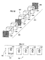
- FIG 12 shows the basic structure of a multilayer guest-host color filter 800.
- Three SSFLC cells 801, 802 and 803, are arranged optically in series along reference axis 804. Each cell contains a uniformly aligned, 45° tilt angle smectic C* FLC.
- Each of the liquid crystal cells 801, 802, 803 is oriented with its alignment direction parallel to a reference vertical.
- Leads connect sets of facing electrodes 805, 806 to an electrical driving means 807, which can independently switch each SSFLC cell 801, 802, 803.
- a reflecting linear polarizer 808 is placed adjacent to one end of the composite of SSFLC cells 801, 802, 803, with its axis parallel to the reference vertical, in accordance with an embodiment of the invention.
- the filter 800 may be illuminated from either end.
- the liquid crystal in each cell 801, 802, 803 is doped with one or more pleochroic dyes, which together selectively absorb light of a given wavelength region that is polarized parallel to the long axis of the dye molecule. All wavelengths are transmitted for light polarized perpendicular to this axis.
- the guest dye molecules orient themselves parallel to the liquid crystal host molecules and can be switched through 90° along with the liquid crystal host molecules when an electric field is applied.
- the dyes are chosen so the three liquid crystal cells can transmit red, green, and blue light, respectively, or, cyan, magenta, and yellow light, respectively.
- the primary colors are additive and only one liquid crystal cell is switched at a given time to transmit a primary color.
- the primary colors are subtractive and two liquid crystal cells must be switched together to give a resulting primary color, which is additive.
- a frame-sequential video system would generate an arbitrary color in time-sequential frames of the additive primary colors.
- FIG 13 shows the structure of a three-SSFLC pleochroic polarizer color-selective filter 900.
- the filter 900 employs two SSFLC cells 901, 902 and three pleochroic polarizers 903, 904, 905 to generate color, and a third (optional) SSFLC cell 906 and reflecting linear polarizer 907 to ensure that all the output colors are polarized in the same plane.
- the reflecting linear polarizer 907 also serves to greatly increase the color purity at the output.
- the filter 900 can be divided into three stages followed by the reflecting linear polarizer 907 and can work with a monochrome video display 908.
- Each stage consists of the primary-color pleochroic polarizer (i.e., 903, 904, or 905) followed by a 45° switching angle SSFLC device (i.e., 901, 902, or 906), as shown in Figure 13.
- the color generating part of the filter consists of the pleochroic polarizer (blue-green) 903 and the pleochroic polarizer (red-green) 904, with the two SSFLC cells 901, 902 in between Blue-green means, for instance, that blue and green are polarized along the same axis, and red light is unpolarized.
- the first SSFLC cell 901 is adjacent the blue-green polarizer 903 and the second SSFLC cell 902 is adjacent the red-green polarizer 904, with the third blue-red pleochroic polarizer 905 between the first and second cells 901 and 902.
- the axes of the end pleochroic polarizers 903 and 904 are oriented parallel to a reference vertical, while the middle pleochroic polarizer 905 has its axis in the orthogonal direction.
- the SSFLC devices are oriented with one of their optic axis directions parallel to the reference vertical, with the switching sense to the other optic axis direction being arbitrary.
- the filter 900 transmits blue light, which is horizontally polarized.
- the filter 900 transmits red light, which is vertically polarized.
- both SSFLC cells 901, 902 are switched to their non-vertical state, the filter 900 transmits vertically polarized light of substantially all colors.
- the optional third SSFLC cell 906, oriented in the same way as the first two, can be placed adjacent to the pleochroic polarizer 904, followed by the (color-neutral) reflecting linear polarizer 907 with its axis again oriented parallel to the reference vertical.
- the third SSFLC cell 906 is left vertical for the green and red filter states, but is switched to its other state for the blue-transmitting filter state. Adding the third SSFLC cell 906 enables the filter 900 to have all of its primary color states have the same output polarization. This is advantageous, for example, if the filter 900 is used in conjunction with a liquid crystal display that is polarization sensitive.
- the neutral reflecting linear polarizer also improves the overall color saturation of the filter 900 with most practical implementations of colored polarizers. It is obvious that the positions within the filter 900 of each pleochroic polarizer 903, 904, 905 can be rearranged, with correspondingly different switching combinations for each primary color, without departing from the scope of the invention.
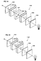
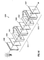
- Figures 14, 15, and 16 show a 1-stage filter with a birefringent element, a 1-stage filter with no birefringent element, and a 2-stage filter, respectively, in accordance with embodiments of the invention. These are color-selective interference filters 1000, 1100, and 1200, respectively.
- the 1-stage filter 1000 consists of a birefringent element 1001, two SSFLC devices 1002, 1003, two reflecting linear polarizers 1004, 1005, an optional set of one or more colored filters 1006, an optional diffuser element (not shown), and a reflective surface (not shown).
- the birefringent element 1001 is situated between the two SSFLC devices 1002, 1003, and all three elements together are situated between the parallel reflecting linear polarizers 1004, 1005.
- the reflecting linear polarizers 1004, 1005 have their axes oriented parallel to a reference vertical and the optic axis of the birefringent element 1001 is oriented at 45° to this direction.
- the SSFLC devices 1002, 1003 contain a 45° switching angle FLC and are oriented so that their optic axes may be switched parallel to the optic axis of the birefringent element 1001, or parallel to the axes of the reflecting linear polarizers 1004, 1005.
- Figure 15, which illustrates the 1-stage filter 1100 is a special case of the 1-stage filter 1000 shown in Figure 14.
- the 1-stage filter 1100 is constructed exactly as described for the filter 1000, except there is no birefringent element, such as the element 1001.
- a passive filter that always blocks transmission of violet light.
- a filter 412 can be placed anywhere in the path of the selective-color filter system 1000, 1100, including at the input, before the reflecting linear polarizer 1005, as shown in the Figures 14 and 15. More details on the operation of the filters 1000 and 1100 are included in the aforementioned U.S. Pat. No. 5,347,378.
- the 2-stage filter 1200 shown in Figure 16 consists of two birefringent elements 1201, 1202, two SSFLC devices 1203, 1204, three reflecting linear polarizers 1205, 1206, 1207, and an optional diffuser element (not shown).
- a colored filter system 1208 shown in Figure 16, as described in reference to the 1-stage filters 1000, 1100, and/or a reflecting surface are also included.
- the birefringent element 1201, 1202 is placed adjacent to the SSFLC device 1203, 1204 (the order being unimportant) with both elements (i.e., one of the birefringent elements and one of the SSFLC devices) together being situated between the reflecting linear polarizer (i.e., between the polarizers 1205, 1206 and between the polarizers 1206, 1207, respectively).
- the second polarizer 1206 of the first stage 1211 also serves as the first polarizer for the second stage 1212.
- the reflecting linear polarizers 1205, 1206, 1207 have their axes oriented parallel to a reference vertical, and the optic axis of each of the birefringent elements 1201, 1202 is oriented at 45° to this direction.
- Each SSFLC device 1203, 1204 contains a 45° switching angle FLC and is oriented in either of two ways: the first way allows the optic axis of the device to be switched between the polarizer (1205, 1206, 1207) axis direction and a direction parallel to the optic axis of the birefringent element 1201, 1202; the second way allows the same optic axis to be switched between the polarizer (1205, 1206, 1207) axis direction and a direction perpendicular to the optic axis of the birefringent element 1201, 1202.
- One of these two geometries is employed in obtaining the three primary colors, depending upon the 2-stage filter 1200 being used.
- the 2-stage filter 1200 embodiments can be operated in either the reflective or the transmissive mode.
- a reflective surface is placed at one end of the 2-stage filter 1200 adjacent to the reflecting linear polarizer (i.e., adjacent to 1205 or 1207).
- the opposite end then becomes the input and output to the filter 1200 and a diffuser element may be situated at this end.
- Some of the embodiments employ one or more of the colored glass filters 1208 to improve the color saturation while others do not.
- FIGS 17A, 17B and 17C show color shutters 1300, 1400, and 1500, respectively.
- the shutters 1300, 1400, 1500 are other variations of two-color shutters that use a linear polarizer.
- the linear polarizer is a reflecting linear polarizer, in accordance with embodiments of the invention, preferably with a clean-up absorptive linear polarizer.
- Figures 17A and 17B show the color shutters 1300 and 1400 that include reflecting linear polarizers 1302 and 1402, respectively.
- Figure 17C shows the color shutter 1500 that includes reflecting linear polarizers 1502 and 1504. Liquid crystal elements LC1 1506 and LC2 1508 in the color shutter 1500 provide controllable rotation of polarization to allow for color shutter 1500 operation.
- color shutters that include reflecting linear polarizers can be used in projection display applications.
- the reflecting linear polarizers are used to reflect the light that would have been absorbed by prior art color shutters.
- the overheating and degradation problems have been resolved and projection display systems using sequential color operation can be built and operate reliably.
Landscapes
- Physics & Mathematics (AREA)
- Nonlinear Science (AREA)
- Optics & Photonics (AREA)
- Engineering & Computer Science (AREA)
- General Physics & Mathematics (AREA)
- Crystallography & Structural Chemistry (AREA)
- Chemical & Material Sciences (AREA)
- Mathematical Physics (AREA)
- High Energy & Nuclear Physics (AREA)
- General Engineering & Computer Science (AREA)
- Multimedia (AREA)
- Spectroscopy & Molecular Physics (AREA)
- Signal Processing (AREA)
- Liquid Crystal (AREA)
- Polarising Elements (AREA)
- Devices For Indicating Variable Information By Combining Individual Elements (AREA)
Applications Claiming Priority (4)
| Application Number | Priority Date | Filing Date | Title |
|---|---|---|---|
| US5429297P | 1997-07-31 | 1997-07-31 | |
| US54292P | 1997-07-31 | ||
| US110652 | 1998-07-07 | ||
| US09/110,652 US6204901B1 (en) | 1997-07-31 | 1998-07-07 | Liquid crystal color shutters that include reflective polarizers that pass color components of light of a first polarization and that reflect a majority of color components of light of a second polarization |
Publications (2)
| Publication Number | Publication Date |
|---|---|
| EP0895116A2 true EP0895116A2 (de) | 1999-02-03 |
| EP0895116A3 EP0895116A3 (de) | 1999-12-29 |
Family
ID=26732846
Family Applications (1)
| Application Number | Title | Priority Date | Filing Date |
|---|---|---|---|
| EP98305983A Withdrawn EP0895116A3 (de) | 1997-07-31 | 1998-07-28 | Farbselektive Flüssigkristall-Lichtventile mit reflektierenden Polarizatoren |
Country Status (6)
| Country | Link |
|---|---|
| US (1) | US6204901B1 (de) |
| EP (1) | EP0895116A3 (de) |
| JP (1) | JPH11142838A (de) |
| KR (1) | KR19990014296A (de) |
| CN (1) | CN1154868C (de) |
| SG (1) | SG87003A1 (de) |
Cited By (3)
| Publication number | Priority date | Publication date | Assignee | Title |
|---|---|---|---|---|
| WO2001009676A1 (en) * | 1999-07-31 | 2001-02-08 | Thomson Training & Simulation Limited | Image display apparatus |
| WO2001023919A1 (en) * | 1999-09-29 | 2001-04-05 | Fujitsu General Limited | Polarized light color filter and video projector comprising the same |
| EP2063310A3 (de) * | 2007-11-20 | 2010-06-09 | Cambridge Research & Instrumentation, Inc. | Doppelbrechender Filter mit reflektiven Polarisatoren und dichroitischen Elementen |
Families Citing this family (15)
| Publication number | Priority date | Publication date | Assignee | Title |
|---|---|---|---|---|
| DE69811201T2 (de) * | 1997-07-18 | 2003-08-14 | Citizen Watch Co., Ltd. | Flüssigkristallanzeige |
| DE19815337C2 (de) * | 1998-04-06 | 2001-07-05 | Deutsche Telekom Ag | Vorrichtung zur lokalen Abschwächung der Lichtintensität im Sehfeld einer lichtempfindlichen Beobachtungseinrichtung |
| JP3997602B2 (ja) * | 1998-05-13 | 2007-10-24 | ソニー株式会社 | 調光装置 |
| JP3766586B2 (ja) * | 2000-10-02 | 2006-04-12 | 株式会社日立製作所 | 光学エンジン、映像表示装置及び色切替方法 |
| RU2226293C2 (ru) * | 2001-10-02 | 2004-03-27 | ОПТИВА, Инк. | Панель дисплея и многослойная пластина для ее изготовления |
| JP2003302699A (ja) * | 2002-02-05 | 2003-10-24 | Sharp Corp | 画像表示装置および画像シフト素子 |
| JP4822432B2 (ja) * | 2006-07-25 | 2011-11-24 | 日東電工株式会社 | 液晶パネル、及び液晶表示装置 |
| US20080226844A1 (en) * | 2007-03-12 | 2008-09-18 | Jds Uniphase Corporation | Space-Variant Liquid Crystal Waveplate |
| US8107152B2 (en) * | 2007-08-29 | 2012-01-31 | Nova Photonics | Electro-optical tunable birefringent filter |
| KR101306359B1 (ko) | 2010-07-27 | 2013-09-09 | 김주원 | 편광디스플레이장치 |
| JP5909975B2 (ja) * | 2011-10-06 | 2016-04-27 | ソニー株式会社 | 撮像装置および電子機器 |
| US20130120695A1 (en) * | 2011-10-26 | 2013-05-16 | Coadna Photonics Inc. | Tunable Flat-Top Liquid Crystal Optical Filter |
| DE102014113700A1 (de) * | 2014-09-23 | 2016-03-24 | Hella Kgaa Hueck & Co. | Scheinwerfer für Fahrzeuge |
| FR3054328B1 (fr) * | 2016-07-22 | 2019-08-16 | Valeo Comfort And Driving Assistance | Dispositif de generation d'image et afficheur tete haute |
| WO2019165641A1 (en) * | 2018-03-02 | 2019-09-06 | Hong Kong Applied Science and Technology Research Institute Company Limited | Beam-steering apparatus with fast response and enhanced steering resolution |
Family Cites Families (48)
| Publication number | Priority date | Publication date | Assignee | Title |
|---|---|---|---|---|
| DE2915847C2 (de) * | 1978-09-29 | 1986-01-16 | Nitto Electric Industrial Co., Ltd., Ibaraki, Osaka | Elektrooptisch aktivierbare Anzeige |
| US4544237A (en) | 1981-12-28 | 1985-10-01 | Hughes Aircraft Company | High efficiency optical tank for two-color liquid crystal light valve image projection with color selective prepolarization |
| US4425028A (en) | 1981-12-28 | 1984-01-10 | Hughes Aircraft Company | High efficiency optical tank for three color liquid crystal light valve image projection with color selective prepolarization and single projection lens |
| JPS6113885A (ja) | 1984-06-29 | 1986-01-22 | Sony Corp | 投射型画像表示装置 |
| GB8804402D0 (en) | 1988-02-25 | 1988-03-23 | Emi Plc Thorn | Display device |
| JP2731169B2 (ja) | 1988-07-18 | 1998-03-25 | 株式会社日立製作所 | 近距離観視用投写形ディスプレイ装置 |
| JPH02211418A (ja) | 1989-02-13 | 1990-08-22 | Seiko Epson Corp | 光学装置 |
| US5486949A (en) | 1989-06-20 | 1996-01-23 | The Dow Chemical Company | Birefringent interference polarizer |
| US5122905A (en) | 1989-06-20 | 1992-06-16 | The Dow Chemical Company | Relective polymeric body |
| JPH0363690A (ja) | 1989-07-31 | 1991-03-19 | Canon Inc | 投射型表示装置 |
| GB8922415D0 (en) | 1989-10-05 | 1989-11-22 | Emi Plc Thorn | A screen and projector for use in a front projection system |
| US5132826A (en) | 1989-10-30 | 1992-07-21 | The University Of Colorado Foundation, Inc. | Ferroelectric liquid crystal tunable filters and color generation |
| US5243455A (en) | 1990-05-11 | 1993-09-07 | The University Of Colorado Foundation, Inc. | Chiral smectic liquid crystal polarization interference filters |
| JP3191292B2 (ja) | 1989-12-18 | 2001-07-23 | セイコーエプソン株式会社 | 投写型表示装置 |
| JPH03241983A (ja) | 1990-02-20 | 1991-10-29 | Canon Inc | 背面投写型受像機 |
| JPH03243932A (ja) | 1990-02-22 | 1991-10-30 | Canon Inc | 背面投写型受像機 |
| JPH0453929A (ja) | 1990-06-22 | 1992-02-21 | Fujitsu Ltd | 反射型液晶装置 |
| GB9026151D0 (en) | 1990-11-30 | 1991-01-16 | Emi Plc Thorn | Display device |
| JP2575558Y2 (ja) | 1990-12-26 | 1998-07-02 | エルジー電子株式会社 | 液晶投写形ディスプレイの光学系構造 |
| FR2673006B1 (fr) | 1991-02-19 | 1993-10-22 | Hughes Aircraft Cy | Systeme de projection a reflexion a valve de lumiere a cristal liquide. |
| US5347378A (en) | 1991-04-04 | 1994-09-13 | Displaytech, Inc. | Fast switching color filters for frame-sequential video using ferroelectric liquid crystal color-selective filters |
| US5692820A (en) | 1992-02-20 | 1997-12-02 | Kopin Corporation | Projection monitor |
| US5467154A (en) | 1992-02-20 | 1995-11-14 | Kopin Corporation | Projection monitor |
| US5416618A (en) | 1992-11-10 | 1995-05-16 | The United States Of America As Represented By The Administrator Of The National Aeronautics & Space Administration | Full complex modulation using two one-parameter spatial light modulators |
| US5333072A (en) | 1992-12-31 | 1994-07-26 | Minnesota Mining And Manufacturing Company | Reflective liquid crystal display overhead projection system using a reflective linear polarizer and a fresnel lens |
| US5325218A (en) | 1992-12-31 | 1994-06-28 | Minnesota Mining And Manufacturing Company | Cholesteric polarizer for liquid crystal display and overhead projector |
| JP3168770B2 (ja) | 1993-06-03 | 2001-05-21 | 松下電器産業株式会社 | 偏光装置および該偏光装置を用いた投写型表示装置 |
| US5337106A (en) | 1993-06-09 | 1994-08-09 | Kowa Company, Ltd. | Liquid-crystal image director for single-lens-reflex camera |
| US5548422A (en) | 1993-06-28 | 1996-08-20 | In Focus Systems, Inc. | Notch filters with cholesteric polarizers with birefringent film and linear polarizer |
| US5619355A (en) | 1993-10-05 | 1997-04-08 | The Regents Of The University Of Colorado | Liquid crystal handedness switch and color filter |
| BE1007592A3 (nl) * | 1993-10-06 | 1995-08-16 | Philips Electronics Nv | Reflecterend beeldprojectiescherm en beeldprojectiesysteem bevattende een dergelijk beeldprojectiescherm. |
| BE1007864A3 (nl) | 1993-12-10 | 1995-11-07 | Philips Electronics Nv | Beeldprojectiesysteem. |
| CN1052795C (zh) * | 1993-12-21 | 2000-05-24 | 美国3M公司 | 光学显示器 |
| JP3278521B2 (ja) | 1994-01-28 | 2002-04-30 | 松下電器産業株式会社 | 背面投写型画像表示装置 |
| US5467146A (en) | 1994-03-31 | 1995-11-14 | Texas Instruments Incorporated | Illumination control unit for display system with spatial light modulator |
| US5627666A (en) * | 1994-07-27 | 1997-05-06 | Board Of Regents Of The University Of Colorado | Liquid crystal phase modulator using cholesteric circular polarizers |
| SG47360A1 (en) | 1994-11-14 | 1998-04-17 | Hoffmann La Roche | Colour display with serially-connected lc filters |
| KR0147607B1 (ko) | 1994-11-25 | 1998-09-15 | 김광호 | 반사형 액정 투사장치의 광학계 |
| US5517340A (en) | 1995-01-30 | 1996-05-14 | International Business Machines Corporation | High performance projection display with two light valves |
| US5594591A (en) | 1995-02-01 | 1997-01-14 | Pioneer Electronic Corporation | Prism system and a liquid crystal projection device |
| US5751384A (en) | 1995-05-23 | 1998-05-12 | The Board Of Regents Of The University Of Colorado | Color polarizers for polarizing an additive color spectrum along a first axis and it's compliment along a second axis |
| US5999240A (en) * | 1995-05-23 | 1999-12-07 | Colorlink, Inc. | Optical retarder stack pair for transforming input light into polarization states having saturated color spectra |
| US5822021A (en) * | 1996-05-14 | 1998-10-13 | Colorlink, Inc. | Color shutter liquid crystal display system |
| US5658490A (en) * | 1995-04-07 | 1997-08-19 | Board Of Regents Of The University Of Colorado | Liquid crystal achromatic compound retarder |
| US5929946A (en) * | 1995-05-23 | 1999-07-27 | Colorlink, Inc. | Retarder stack for preconditioning light for a modulator having modulation and isotropic states of polarization |
| US5621486A (en) | 1995-06-22 | 1997-04-15 | International Business Machines Corporation | Efficient optical system for a high resolution projection display employing reflection light valves |
| JPH09159983A (ja) | 1995-12-08 | 1997-06-20 | Mitsubishi Electric Corp | 投写型表示装置及びマルチビジョン投写型表示装置 |
| US6181386B1 (en) | 1995-12-29 | 2001-01-30 | Duke University | Projecting images |
-
1998
- 1998-07-07 US US09/110,652 patent/US6204901B1/en not_active Expired - Fee Related
- 1998-07-24 SG SG9802653A patent/SG87003A1/en unknown
- 1998-07-28 EP EP98305983A patent/EP0895116A3/de not_active Withdrawn
- 1998-07-30 KR KR1019980030797A patent/KR19990014296A/ko not_active Ceased
- 1998-07-31 JP JP10217823A patent/JPH11142838A/ja active Pending
- 1998-07-31 CN CNB981179177A patent/CN1154868C/zh not_active Expired - Fee Related
Cited By (6)
| Publication number | Priority date | Publication date | Assignee | Title |
|---|---|---|---|---|
| WO2001009676A1 (en) * | 1999-07-31 | 2001-02-08 | Thomson Training & Simulation Limited | Image display apparatus |
| US6967641B1 (en) | 1999-07-31 | 2005-11-22 | Thomson Training & Simulation Limited | Image display apparatus |
| WO2001023919A1 (en) * | 1999-09-29 | 2001-04-05 | Fujitsu General Limited | Polarized light color filter and video projector comprising the same |
| US6876403B1 (en) | 1999-09-29 | 2005-04-05 | Fujitsu General Limited | Polarized light color filter and video projector comprising the same |
| EP2063310A3 (de) * | 2007-11-20 | 2010-06-09 | Cambridge Research & Instrumentation, Inc. | Doppelbrechender Filter mit reflektiven Polarisatoren und dichroitischen Elementen |
| US7982955B2 (en) | 2007-11-20 | 2011-07-19 | Cambridge Research & Instrumentation, Inc. | Birefringent filter using reflective polarizers and dichroic elements |
Also Published As
| Publication number | Publication date |
|---|---|
| SG87003A1 (en) | 2002-03-19 |
| JPH11142838A (ja) | 1999-05-28 |
| US6204901B1 (en) | 2001-03-20 |
| CN1154868C (zh) | 2004-06-23 |
| KR19990014296A (ko) | 1999-02-25 |
| EP0895116A3 (de) | 1999-12-29 |
| CN1224177A (zh) | 1999-07-28 |
Similar Documents
| Publication | Publication Date | Title |
|---|---|---|
| EP0898841B1 (de) | Farbselektive lichtmodulatoren | |
| US6273571B1 (en) | Display architectures using an electronically controlled optical retarder stack | |
| US5999240A (en) | Optical retarder stack pair for transforming input light into polarization states having saturated color spectra | |
| US5929946A (en) | Retarder stack for preconditioning light for a modulator having modulation and isotropic states of polarization | |
| US6049367A (en) | Polarization manipulating device modulator with retarder stack which preconditions light for modulation and isotropic states | |
| US6204901B1 (en) | Liquid crystal color shutters that include reflective polarizers that pass color components of light of a first polarization and that reflect a majority of color components of light of a second polarization | |
| US7511787B2 (en) | Color filters and sequencers using color-selective light modulators | |
| US6667784B2 (en) | Color filters, sequencers and displays using color selective light modulators | |
| US6490017B1 (en) | Separating white light into polarized, colored light | |
| JP2001228455A (ja) | 映像投射装置 | |
| JPS63132218A (ja) | 切換可能なカラーフィルタ | |
| US20080198456A1 (en) | Laminated retarder stack | |
| JP4637370B2 (ja) | 変調カラー画像を形成するための光学システム | |
| JP2008020921A (ja) | 光モジュレータおよびシーケンサー | |
| KR0144459B1 (ko) | 영상 투사 장치 | |
| US20060187520A1 (en) | Imaging light source with polarization and color recovery | |
| KR19990055242A (ko) | 투사형 화상 표시 장치 | |
| JP3491809B2 (ja) | 投影型画像表示装置 | |
| JP3659637B2 (ja) | 投影型画像表示装置 | |
| KR20000003888A (ko) | 투사형 화상 표시 장치 | |
| JP3102815B2 (ja) | 液晶表示装置 | |
| Fünfschilling et al. | Video‐compatible subtractive color projection with cholesteric liquid‐crystal band‐modulation filters | |
| WO2004088362A2 (en) | MEANS OF COMPENSATION TO INCREASE THE CONTRAST RATIO OF LCoS BASED VIDEO PROJECTION SYSTEMS |
Legal Events
| Date | Code | Title | Description |
|---|---|---|---|
| PUAI | Public reference made under article 153(3) epc to a published international application that has entered the european phase |
Free format text: ORIGINAL CODE: 0009012 |
|
| AK | Designated contracting states |
Kind code of ref document: A2 Designated state(s): AT BE CH DE DK ES FI FR GB GR IE IT LI LU MC NL PT SE |
|
| AX | Request for extension of the european patent |
Free format text: AL;LT;LV;MK;RO;SI |
|
| PUAL | Search report despatched |
Free format text: ORIGINAL CODE: 0009013 |
|
| AK | Designated contracting states |
Kind code of ref document: A3 Designated state(s): AT BE CH CY DE DK ES FI FR GB GR IE IT LI LU MC NL PT SE |
|
| AX | Request for extension of the european patent |
Free format text: AL;LT;LV;MK;RO;SI |
|
| 17P | Request for examination filed |
Effective date: 20000627 |
|
| AKX | Designation fees paid |
Free format text: GB |
|
| AXX | Extension fees paid |
Free format text: AL PAYMENT 20000627;LT PAYMENT 20000627;LV PAYMENT 20000627;RO PAYMENT 20000627;SI PAYMENT 20000627 |
|
| REG | Reference to a national code |
Ref country code: DE Ref legal event code: 8566 |
|
| RBV | Designated contracting states (corrected) |
Designated state(s): GB |
|
| RBV | Designated contracting states (corrected) |
Designated state(s): AT BE CH CY DE DK ES FI FR GB GR IE IT LI LU MC NL PT |
|
| RBV | Designated contracting states (corrected) |
Designated state(s): AT BE CH DE DK ES FI FR GB GR IE IT LI LU MC NL PT SE |
|
| 17Q | First examination report despatched |
Effective date: 20020111 |
|
| RAP1 | Party data changed (applicant data changed or rights of an application transferred) |
Owner name: DUKE UNIVERSITY |
|
| STAA | Information on the status of an ep patent application or granted ep patent |
Free format text: STATUS: THE APPLICATION IS DEEMED TO BE WITHDRAWN |
|
| 18D | Application deemed to be withdrawn |
Effective date: 20040923 |