EP0895400A2 - Dispositif et procédé de traitement d'information, et moyen de stockage pour ceux-ci - Google Patents
Dispositif et procédé de traitement d'information, et moyen de stockage pour ceux-ci Download PDFInfo
- Publication number
- EP0895400A2 EP0895400A2 EP98114103A EP98114103A EP0895400A2 EP 0895400 A2 EP0895400 A2 EP 0895400A2 EP 98114103 A EP98114103 A EP 98114103A EP 98114103 A EP98114103 A EP 98114103A EP 0895400 A2 EP0895400 A2 EP 0895400A2
- Authority
- EP
- European Patent Office
- Prior art keywords
- image data
- data
- transmitted
- information processing
- image quality
- Prior art date
- Legal status (The legal status is an assumption and is not a legal conclusion. Google has not performed a legal analysis and makes no representation as to the accuracy of the status listed.)
- Withdrawn
Links
Images











Classifications
-
- H—ELECTRICITY
- H04—ELECTRIC COMMUNICATION TECHNIQUE
- H04L—TRANSMISSION OF DIGITAL INFORMATION, e.g. TELEGRAPHIC COMMUNICATION
- H04L12/00—Data switching networks
- H04L12/28—Data switching networks characterised by path configuration, e.g. LAN [Local Area Networks] or WAN [Wide Area Networks]
- H04L12/40—Bus networks
- H04L12/40052—High-speed IEEE 1394 serial bus
- H04L12/40058—Isochronous transmission
-
- G—PHYSICS
- G06—COMPUTING OR CALCULATING; COUNTING
- G06F—ELECTRIC DIGITAL DATA PROCESSING
- G06F13/00—Interconnection of, or transfer of information or other signals between, memories, input/output devices or central processing units
- G06F13/38—Information transfer, e.g. on bus
- G06F13/42—Bus transfer protocol, e.g. handshake; Synchronisation
- G06F13/4282—Bus transfer protocol, e.g. handshake; Synchronisation on a serial bus, e.g. I2C bus, SPI bus
- G06F13/4291—Bus transfer protocol, e.g. handshake; Synchronisation on a serial bus, e.g. I2C bus, SPI bus using a clocked protocol
-
- H—ELECTRICITY
- H04—ELECTRIC COMMUNICATION TECHNIQUE
- H04L—TRANSMISSION OF DIGITAL INFORMATION, e.g. TELEGRAPHIC COMMUNICATION
- H04L12/00—Data switching networks
- H04L12/28—Data switching networks characterised by path configuration, e.g. LAN [Local Area Networks] or WAN [Wide Area Networks]
- H04L12/40—Bus networks
- H04L12/40052—High-speed IEEE 1394 serial bus
- H04L12/40117—Interconnection of audio or video/imaging devices
-
- H—ELECTRICITY
- H04—ELECTRIC COMMUNICATION TECHNIQUE
- H04L—TRANSMISSION OF DIGITAL INFORMATION, e.g. TELEGRAPHIC COMMUNICATION
- H04L12/00—Data switching networks
- H04L12/28—Data switching networks characterised by path configuration, e.g. LAN [Local Area Networks] or WAN [Wide Area Networks]
- H04L12/40—Bus networks
- H04L12/40052—High-speed IEEE 1394 serial bus
- H04L12/40123—Interconnection of computers and peripherals
-
- H—ELECTRICITY
- H04—ELECTRIC COMMUNICATION TECHNIQUE
- H04N—PICTORIAL COMMUNICATION, e.g. TELEVISION
- H04N1/00—Scanning, transmission or reproduction of documents or the like, e.g. facsimile transmission; Details thereof
- H04N1/00127—Connection or combination of a still picture apparatus with another apparatus, e.g. for storage, processing or transmission of still picture signals or of information associated with a still picture
- H04N1/00204—Connection or combination of a still picture apparatus with another apparatus, e.g. for storage, processing or transmission of still picture signals or of information associated with a still picture with a digital computer or a digital computer system, e.g. an internet server
-
- H—ELECTRICITY
- H04—ELECTRIC COMMUNICATION TECHNIQUE
- H04N—PICTORIAL COMMUNICATION, e.g. TELEVISION
- H04N1/00—Scanning, transmission or reproduction of documents or the like, e.g. facsimile transmission; Details thereof
- H04N1/32—Circuits or arrangements for control or supervision between transmitter and receiver or between image input and image output device, e.g. between a still-image camera and its memory or between a still-image camera and a printer device
- H04N1/333—Mode signalling or mode changing; Handshaking therefor
- H04N1/33307—Mode signalling or mode changing; Handshaking therefor prior to start of transmission, input or output of the picture signal only
- H04N1/33315—Mode signalling or mode changing; Handshaking therefor prior to start of transmission, input or output of the picture signal only reading or reproducing mode only, e.g. sheet size, resolution
Definitions
- the present invention relates to an information processing apparatus utilizing an interface with variable bus band width, and a method and a memory medium therefor.
- peripheral equipment of the personal computer most frequently used are hard disks and printers, and such peripherals are connected and communicate with the personal computer with a general digital interface for small computers, represented by SCSI.
- recording/reproducing device such as a digital camera or a digital video camera is a peripheral of the personal computer, employed as input means therefor, and there has recently been remarkable progress, with increasing users, in the technology of fetching a still image or a moving image, taken with such digital camera or digital video camera, into the personal computer, then storing such image in the hard disk or editing such image on the personal computer and obtaining a color print of such image with a printer.
- the data are communicated without an interface such as SCSI mentioned above, and, for transmitting the information of a large data amount such as the image data, there is required a general-purpose digital interface with a high data transfer rate.
- the IEEE1394 is recently attracting attention.
- the bus band width is assigned not only to the data transmission to the printer but also to the data exchange with other equipment, so that the bus band width or the data transfer amount per unit time is not constant. Consequently the data transfer cannot be realized with a high gradation and a high resolution, and the data transfer with a low gradation and a low resolution results in a printing operation with a low image quality even when a wide bus band width can be secured.
- the object of the present invention is to provide an information processing apparatus capable of optimum control according to the acquired bus band width, and an information processing method and a memory medium therefor.
- an information processing apparatus for generating image data in a generation unit and transmitting the generated image data by synchronous transfer through a transmission unit
- the apparatus comprising identification means for identifying the data amount of synchronous transfer, transmittable through the transmission unit at every predetermined time; judgment means for judging whether the image data generated in the generation unit can be transmitted through the transmission unit within the data amount of synchronous transfer identified by the identification means; resetting means for resetting the image quality of the image data to be transmitted through the transmission unit in case the judgment means judges that the image data cannot be transmitted; and control means for causing the generation unit to generate the image data to be transmitted through the transmission unit with the image quality reset by the resetting means.
- an information processing method for use in an information processing apparatus for generating image data in a generation unit and transmitting the generated image data by synchronous transfer through a transmission unit, the method comprising an identification step of identifying the data amount of synchronous transfer, transmittable through the transmission unit at every predetermined time; a judgment step of judging whether the image data generated in the generation unit can be transmitted through the transmission unit within the data amount of synchronous transfer identified in the identification step; a resetting step of resetting the image quality of the image data to be transmitted through the transmission unit in case the judgment step judges that the image data cannot be transmitted; and a control step of causing the generation unit to generate the image data to be transmitted through the transmission unit with the image quality reset by the resetting step.
- a memory medium storing a computer readable program for use in an information processing apparatus for generating image data in a generation unit and transmitting the generated image data by synchronous transfer through a transmission unit, the program comprising an identification step of identifying the data amount of synchronous transfer, transmittable through the transmission unit at every predetermined time; a judgment step of judging whether the image data generated in the generation unit can be transmitted through the transmission unit within the data amount of synchronous transfer identified in the identification step; a resetting step of resetting the image quality of the image data to be transmitted through the transmission unit in case the judgement step judges that the image data cannot be transmitted; and a control step of causing the generation unit to generate the image data to he transmitted through the transmission unit with the image quality reset by the resetting step.
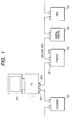
- Fig. 1 shows an example of the network configuration in which the present invention is applicable.
- Fig. 1 shows the state of connection of a personal computer, a printer etc. connected through the IEEE1394 interface.
- Fig. 7 shows an example of the network system constructed with the 1394 serial bus.
- the system consists of apparatus A, B, C, D, E, F, G and H, and each of the connections A-B, A-C, B-D, D-E, C-F, C-G and C-H is made with a twisted pair cable of the 1394 serial bus.
- the apparatus A to H can be, for example, a personal computer, a digital VCR, a DVD, a digital camera, a hard disk, a monitor etc.
- the apparatus can be connected with a large freedom, by the mixture of daisy chain method and node branched method.
- Each apparatus has its own ID, and such ID's are mutually recognized whereby a network is constituted within the range of connections with the 1394 serial buses.
- Each digital apparatus is connected with a 1394 serial bus in succession whereby each apparatus performs a relaying function so that all the apparatus constitute a single network. Also when the cable is connected to the apparatus, the apparatus itself and the connection status thereof can be automatically recognized by the plug and play function, which is a feature of the 1394 serial bus. Also in a system as shown in Fig. 7, when an apparatus is deleted from the system or added thereto, the bus is automatically reset so that the network configuration is reset and reconstructed anew.
- the data transfer rate is available in 100, 200 or 400 Mbps, and the apparatus having an upper transfer rate supports the lower transfer rate to achieve compatibility.
- the data transfer can be achieved in an asynchronous transfer mode for transferring asynchronous data (hereinafter also written as async data) such as control signals, or in an isochronous transfer mode for transferring real-time isochronous data (hereinafter also written as iso data) such as video or audio data.
- the asynchronous data and the isochronous data are transferred in mixed manner within each cycle (usually 125 ⁇ sec), following the transfer of a cycle start packet (CSP) indicating the start of a cycle, with priority given to the isochronous data.
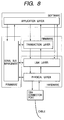
- Fig. 8 shows the components of the 1394 serial bus, having layered structure.
- the hardware component is constituted by a 1394 serial bus cable, of which connector is connected to a connector port.
- a physical layer and a link layer both constituting a hardware realized by an interface chip.
- the physical layer control the encoding and the connector, while the link layer controls the packet transfer and the cycle time.
- a transaction layer realized as a firmware manages the data to be transferred (transaction) and generates read and write commands.
- a serial bus management manages the connection status and ID of the connected apparatus, thereby managing the configuration of the network.
- the above-mentioned hardware and firmware substantially constitute the 1394 serial bus.
- An application layer realized by a software and varying according to the software to be used, defines the state of data on the interface and is defined by a protocol such as the AV protocol.
- the 1394 serial bus is constructed as explained in the foregoing.
- Fig. 9 shows the address space in the 1394 serial bus.
- Each apparatus (node) connected to the 1394 serial bus is given a 64-bit address specific to such node. This address is stored in a ROM, so that each apparatus can always recognize its own node address and the node addresses of other apparatus and can execute communicate with the designated partner.
- the addressing of the 1394 serial bus is based on the IEEE1212 standard, and, in the address, initial 10 bits are used for designating the bus number and next 6 bits are used for designating the node ID number. Subsequent 48 bits constitute the address width assigned to the apparatus and usable as the specific address space. Final 28 bits are used as an area of specific data, for storing the information identifying various apparatus or designating the condition of use.
- the 1394 serial bus technology is constructed as outlined above.
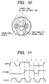
- Fig. 10 is a cross-sectional view of the 1394 serial bus cable, which includes two sets of twisted-pair signal lines and power supply lines which achieves power supply to an apparatus without power source or an apparatus in which the voltage is lowered by a failure.
- the electric power supplied in the power supply lines has a voltage of 8 to 40 V and a DC current of 1.5 A at maximum.
- Fig. 11 shows the principle of the DS-link encoding method for the data transfer format employed in the 1394 serial bus.
- the 1394 serial bus employs the DS-link (data/strobe link) encoding method, which is suitable for high-speed serial data communication and requires two signal lines. Main data are transmitted by one of the twisted paired lines, while a strobe signal is transmitted by the other. At the receiving side, the clock signal can be reproduced by calculating the exclusive logic sum of the communicated data and the strobe signal.
- the DS-link encoding method has the advantages of a higher transfer efficiency in comparison with other serial data transfer method, a smaller circuit magnitude of the controller LSI because the PLL circuit can be dispensed with, and a reduction in the electric power consumption because, in the absence of the data to be transferred, the transceiver circuit of each apparatus can be shifted into a sleep state as the information indicating the idle state need not be transmitted.
- each connected apparatus In the 1394 serial bus, each connected apparatus (node) is given a node ID and is recognized in the network configuration. In case it becomes necessary to recognize the new network configuration because of a change in the network configuration, for example by a change in the number of nodes by the addition or deletion of a node or by the on/off operation of power supply, each node detecting such change transmits a bus reset signal to the bus and enters a mode of recognizing the new network configuration. Such change is detected by detecting a change in the bias voltage on the 1394 port board. Receiving the bus reset signal from a node, the physical layer of each node transmits the generation of bus resetting to the link layer and also transmits the bus reset signal to other nodes.
- the bus resetting is activated when all the nodes finally detect the bus reset signal.
- the bus resetting is also activated by a hardware detection in case of attaching or detaching of the cable or an abnormality in the network, or by a direct command to the physical layer from the host equipment in protocol control. Once the bus resetting is activated, the data transfer is suspended, and is re-started, after the completion of the bus resetting, under the new network configuration.
- each node After the bus resetting, each node enters an operation of assigning the ID to each node for constructing the new network configuration.
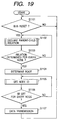
- a general sequence from the bus resetting to the node ID determination Fig. 19 shows the sequence of bus operations from the start of the bus resetting to the determination of the node ID whereupon the data transfer is enabled.
- a step S1101 constantly monitors the start of bus resetting in the network, and, if the bus resetting is generated for example by an on/off operation of the power supply in a node, the sequence proceeds to a step S1102, in which, in the reset state of the network, the parent-child relationship is declared between the directly connected apparatus in order to identify the connection state of the new network.
- a step S1103 identifies the determination of the parent-child relation in all the nodes
- a step S1104 determines a root. The declaration of the parent-child relationship in the step S1102 is continued, and the root is not determined, until the parent-child relationship is determined in all the nodes.
- a step S1105 executes a node ID setting operation for giving the ID to each node.
- the node ID is set repeatedly in a predetermined order of nodes until the ID's are given to all the nodes.
- a step S1106 identifies that the ID's are set in all the nodes, the new network configuration is recognized in all the nodes and the data transfer is enabled among the nodes, whereupon a step S1107 initiates the data transfer.
- the state of the step S1107 there is again entered the mode of monitoring the generation of bus resetting, and, in case of generation of a bus resetting, there is again repeated the setting operations of the steps S1101 to S1106.
- a step S1201 constantly monitors the generation of bus resetting, and, if generated, the network configuration is reset. Then, as a first step of recognizing again the connection state of the reset network, a step S1202 sets a flag indicating a leaf (node) in each apparatus. Then, in a step S1203, each apparatus checks the number of ports thereof connected to other nodes. In order to start the declaration of the parent-child relationship based on the checked number of ports, a step S1204 checks the number of undefined ports (for which the parent-child relationship is not determined).
- the number of ports is equal to the number of undefined ports, but, with the progress of determination of the parent-child relationships, the number of undefined ports detected in the step S1204 changes.
- the parent-child relationship can only be declared by a leaf. Being a leaf can be known by the confirmation of the port number in the step S1203.
- a leaf declares, to a node connected thereto, that "the leaf is a child and the node is a parent" and terminates the operation.
- a node which is identified to have plural ports and to be a branching node in the step S1203 has a number of undefined ports larger than 1 in the step S1204, it proceeds to a step S1206 in which a branch flag is set. Then it waits in a step S1207 to accept "parent" in the parent-child declaration from the leaf.
- a branch which receives the "parent" position in the step S1207 in the parent-child declaration by the leaf, confirms the number of the undefined ports in the step S1204, and, if the number of the undefined ports becomes 1, it can declare that "it is a child" in the step S1205 to the node connected to the remaining port.
- a branch which has two or more undefined ports in the step S1204 waits again in the step S1207 for accepting the declaration of "parent" from a leaf or another branch.
- the declarations of the parent-child relationship are completed in the entire network, and a step S1208 sets a root flag in the unique node in which the number of undefined ports has become zero (all ports being defined) and a step S1209 recognizes such node as the root. In this manner the operations from the bus resetting to the declarations of the parent-child relationship in all the nodes of the network as shown in Fig. 20 are completed.
- a step S1301 classifies the flag information of the nodes defined as leaves, branches and root in the sequence shown in Fig. 20.
- the ID setting to the nodes can be started from leaves.
- the ID's are set from the smallest number of node (starting from node number 0), in the order of leaves, branches and root.
- a step S1302 sets a number N (natural number) of the leaves present in the network.
- each leaf issues a request for the ID to the root.
- the root executes an arbitration in a step S1304, and a step S1305 gives the ID number to the winning node and informs the losing node of the failure.
- a step S1306 the leaf that has failed in acquiring the ID issues again the request for ID, and a similar operation is repeated.
- a leaf that has acquired the ID transfers the ID, by broadcasting in a step S1307, to all the nodes.
- a step S1308 decreases the number of the remaining leaves. If a step S1309 discriminates that the number of remaining leaves is at least one, the process starting from the ID request in the step S1303 is repeated.
- a step S1310 sets a number M (natural number) of the branches present in the network.
- each branch issues a request for the ID to the root.
- the root executes an arbitration in a step S1312, and gives the ID numbers, starting from a smallest ID number next to those given to the leaves, to the winning branches.
- a step S1313 gives the ID number to the winning node and informs the losing node of the failure.
- the branch that has failed in acquiring the ID issues again the request for ID, and a similar operation is repeated.
- a branch that has acquired the ID transfers the ID, by broadcasting in a step S1315, to all the nodes. After a broadcasting of the node ID information, a step S1316 decreases the number of the remaining branches.
- a step S1317 discriminates that the number of remaining branches is at least one, the process starting from the ID request in the step S1311 is repeated until the ID information is broadcast from all the branches.
- the root being the only node that has not acquired the ID information, assigns the smallest available number as its own ID number in a step S1318, and a step S1319 broadcasts the ID information of the root. In this manner the sequence shown in Fig. 21, after the determination of the parent-child relationship to the ID setting for all the nodes, is completed.
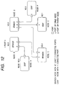
- the network has a hierarchic structure in which nodes A, C are positioned under a root node B and directly connected thereto; a node D is directly connected under the node C; and nodes E, F are directly connected under the node D.
- the parent-child relationship is declared between the directly connected ports of the nodes, in order to recognize the connection state of the nodes.
- the parent assumes a higher rank in the hierarchic structure while the child assumes a lower rank.
- the parent-child relationship is declared at first by the node A.
- the declaration can be basically made by a node that has connection at only one port thereof (such node being called leaf). Such node can detect that it has connection at only one port and can thus recognize it constitutes an end in the network, and the parent-child relationship is determined from the fastest reacting one among such nodes.
- the port of the declaring node node A in the connection A-B
- the port of the other node node B
- the child and the parent are respectively set in the nodes A-B, E-D and F-D.
- the process moves up to the next upper layer, and the parent-child relationship is declared to the still upper layer by the nodes having plural connections (such node being called branch), starting from those which have received the declaration of the parent-child relationship from other nodes.
- the node D declares the parent-child relationship to the node C whereby the node D and C are respectively determined as the child and the parent between these nodes.
- the node C declares the parent-child relationship to the node B connected to another port of the node C, whereby the node C and B are respectively determined as the child and the parent between these nodes.
- the node B which has become the parent finally in all the connected ports, is determined as the root node. There is only one root within the network.
- the node B is determined as the root node, but another node may become the root node if the node B, having received the declaration of the parent-child relationship from the node A, executes the declaration of the parent-child relationship to other nodes at an earlier timing. Stated differently, any node can become the root node depending on the timing of transmission, so that the root node is not necessarily fixed even within a same network structure.
- each node informs its own determined ID to all other nodes (broadcasting function).
- the information of own ID contains the own ID number, information on the connected position, number of ports, number of connected ports, information on the parent-child relationship on each port etc.
- the procedure of assignment of the node ID numbers can be activated from nodes (leaves) having connection at only one port, and the node numbers are assigned sequentially in the order of 0, 1, 2, ... among such nodes.
- the node that has acquired the node ID transmits the information, including the node number, to all the nodes by broadcasting, whereby such ID number is recognized as 'already assigned'.
- the procedure is shifted to the branches and the node ID numbers subsequent to those assigned to the leaves are sequentially assigned to the branches.
- the branches having acquired the node ID numbers broadcast the node ID information in succession, and finally the root node broadcasts the own ID information. Consequently, the root node always have the large node ID number.
- the 1394 serial bus there is always conducted an arbitration of the right to use the bus, prior to the data transfer.
- the 1394 serial bus constitutes a logical network in which each apparatus individually connected relays the transferred signal in such a manner that the transferred signal can be transferred equally to all the apparatus in the network, the arbitration process is required to prevent the collision of the packets, thereby allowing that only one node executes signal transfer at a given time.
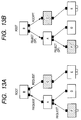
- the arbitration process will be explained in the following with reference to Fig. 13A showing a state of requesting the use of bus, and Fig. 13B showing a state of permitting the use of bus.
- nodes When the arbitration is started, one or plural nodes respectively issue requests for the bus use right to the parent node.
- nodes C and F issue such requests.
- the parent node node A in Fig. 13A
- the requests are finally delivered to the root node which executes the arbitration.
- the root node determines a node to use the bus. This arbitrating operation can only be executed by the root node, and the permission to use the bus is given to the winning node of the arbitration. In Fig. 13B, the permission for the use is given to the node C, but the use by the node F is rejected. A DP (data prefix) packet is transmitted to the losing node in the arbitration, in order to advise the state of rejection. The request for the bus use right of the losing node has to wait until the next arbitration.
- DP data prefix
- the node having won the arbitration and acquired the bus use right, can initiate the data transfer.
- the sequence of arbitration will be explained in the following with reference to Fig. 22.
- the bus has to be in an idle state.
- Each node judges, upon lapse of a predetermined idle time gap length (subaction gap) after the end of a preceding data transfer, that the bus is in the idle state and that it can start the data transfer.
- a step S1401 discriminates whether there has been obtained a gap length, determined in advance according to the data to be transferred such as async data or iso data. The node waits until such predetermined gap length is obtained, since the bus use right for starting the data transfer cannot be requested unless such predetermined gap length is obtained.
- a step S1402 discriminates whether the data to be transferred are present, and, if present, a step S1403 issues a request for the bus use right to the root, in order to secure the bus for data transfer.
- the signal representing the request for the bus use right is relayed by the apparatus in the network as shown in Figs. 13A and 13B, and is finally delivered to the root.
- the step S1402 identifies the absence of the data to be transferred, the node enters a waiting state.
- the root receives, in a step S1404, one or more requests for the bus use right issued in the step S1403, the root checks the number of requesting nodes in a step S1405.
- step S1405 identifies that the number of requesting nodes is 1, such node is given the permission to use the bus immediately thereafter. If the step S1405 identifies that there are plural requesting nodes, the root executes the arbitration for determining a node to which the permission is to be given. The arbitration is made fair to all the nodes so that all the nodes have equal chances of acquiring permission, without such a situation that a same node acquires the permission every time.
- a step S1407 divides, among the plural nodes issuing the requests in the step S1406, a node which acquires the permission to use by the arbitration of the root and other losing nodes.
- a step S1408 the root sends a permission signal to the node which acquires the permission to use as the result of arbitration or which acquires the permission without the arbitration in case the step S1405 identifies that the number of requesting nodes is one.
- the node receiving the permission signal immediately initiates the transfer of the data (packet) to be transmitted.
- the node which has lost the arbitration in the step S1406 and is rejected from the use of bus receives, from the root in a step S1409, a DP (data prefix) packet indicating the failure in arbitration, and the node having received such packet returns to the step S1401 and waits until the predetermined gap length is obtained, in order to issue again the request for using the bus.
- DP data prefix
- the asynchronous transfer is a non-synchronized data transfer.
- Fig. 14 shows the phase changes in time in the asynchronous transfer.
- the initial subaction gap indicates the idle state of the bus.
- the node wishing the data transfer judges that the bus is usable and requests the arbitration for acquiring the bus.
- the data transfer is executed in the packet format. After the data transfer, the transfer process is completed by the receiving node, by the sending of either an ack (acknowledging code) after a short ack gap or a response packet.
- the ack consists of 4-bit information and a 4-bit check sum, contains information indicating a success, a busy state or a pending state and is immediately returned to the transmitting node.
- Fig. 15 shows an example of the packet format in the asynchronous transfer.
- the packet contains, in addition to a data portion and error correction data CRC, a header portion which contains a destination node ID, a source node ID, transfer data length and various codes.
- the asynchronous transfer is a 1-to-1 communication from the source node to the destination node.
- the packet transferred from the source node is delivered to all the nodes in the network, but is read only by the destination node since any node disregards the packet unless it is addressed to the own node.
- the asynchronous transfer is executed in the above-explained manner.
- the isochronous transfer is a synchronized data transfer.
- the isochronous transfer constituting the most important feature of the 1394 serial bus, is particularly suitable for the data requiring real-time transfer, such as video image data or audio data.
- the isochronous transfer is conducted uniformly from the source node to all other nodes by the broadcasting function.
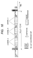
- Fig. 16 shows the phase changes in time in the isochronous transfer, which is executed at a predetermined interval on the bus. This interval is called the isochronous cycle, which is 125 ⁇ sec.
- a cycle start packet indicates the starting time of each cycle and adjust the time of each node.
- the cycle start packet is transmitted by a node called cycle master, which transmits the cycle start packet after a predetermined idle time (subaction gap) following the transfer in the preceding cycle.
- the cycle start packets are transmitted at an interval of 125 ⁇ s.
- the packets of plural kinds can be transferred in distinguished manner within a cycle, by being given different channel ID's.
- real-time transfer can be simultaneously achieved among plural nodes, and the receiving node fetches the data of a desired channel ID only.
- the channel ID does not indicate the address of the destination, but merely gives a logic number to the data. Consequently any packet is transferred by broadcasting from a source node to all other nodes.
- isochronous gap indicates an idle time required, prior to the isochronous transfer, for identifying that the bus is idle. After the lapse of the predetermined idle time, the node wishing the isochronous transfer judges that the bus is idle and requests the arbitration before the transfer.
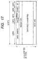
- Fig. 17 shows an example of the packet format for the isochronous transfer.
- the packet divided in each channel contains, in addition to a data portion and error correction data CRC, a header portion which contains a transfer data length, a channel number, various codes and an error correcting header CRC.
- the isochronous transfer is executed in the above-described manner.
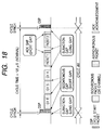
- Fig. 18 shows the phase transitions in time of the transfer state on the bus, containing the isochronous transfer and the asynchronous transfer in mixed manner.
- the isochronous transfer is executed with priority, because, after the cycle start packet, the isochronous transfer can be activated with a gap length (isochronous gap) shorter than that (subaction gap) required for activating the asynchronous transfer. Consequently the isochronous transfer is executed with higher priority than the asynchronous transfer.
- the cycle start packet is transferred from the cycle master to the nodes at the start of a cycle #M.
- the nodes In response the nodes adjust the time, and, after the lapse of a predetermined idle time (isochronous gap), the nodes wishing the isochronous transfer execute arbitration and enter the packet transfer.
- a predetermined idle time isochronous gap
- the nodes wishing the isochronous transfer execute arbitration and enter the packet transfer.
- the channels e, s and k are isochronous transferred in succession.
- the process from the arbitration to the packet transfer is repeated for the number of given channels, and, after the completion of the isochronous transfers in the cycle #M, the asynchronous transfer is enabled.
- the node wishing the asynchronous transfer judges that the arbitration can be started.
- the asynchronous transfer can be executed only if the subaction gap for activating the asynchronous transfer can be obtained within the time from the termination of the isochronous transfer to the time of transfer of the next cycle start packet (cycle synch).
- cycle #m shown in Fig. 18 there are executed the isochronous transfer of three channels and the asynchronous transfer (including ack) of two packets (packet 1 and 2).
- the isochronous transfer is always executed in every cycle if required to maintain the real-time transfer, while the asynchronous transfer may be delayed to the next or later cycle by the shortening of the cycle time. Such delay is also managed by the cycle master.
- the IEEE1394 serial bus functions in the above-explained manner.
- Fig. 1 shows the connection state of a personal computer, a printer etc. connected with the IEEE1394 I/F.
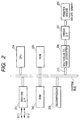
- Fig. 2 is a block diagram showing the interior of a printer 103
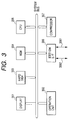
- Fig. 3 is a block diagram showing the interior of a personal computer 101.
- a personal computer 101 there are shown a personal computer 101, and a color laser beam printer 103.
- FIG. 2 showing the configuration of the printer 103, there are shown an IEEE1394 I/F 201; a RAM 202; a decompressor 203 for expanding the compressed data, transferred through the IEEE1394 bus, to restore the original data; CPU 204; a ROM 205 for storing the operation program etc.
- a multivalue-PWM conversion unit 206 for effecting pulse width modulation (PWM) on the multi-value image data transmitted from the personal computer, having a mode of converting 8-bit input data to 8 pulses corresponding to a pixel width and a mode converting 4-bit input data to 4 pulses corresponding a pixel width;
- a printer engine 208 for printing, on a printing sheet, the video data transmitted from the PWM conversion unit 206 through a printer engine I/F 207, and constituted in the present embodiment by a color page printer which receives and prints the CMYK image data in page sequential manner; and a printer engine I/F 207 for transmitting the video data to the printer engine 208 in synchronization with the horizontal and vertical sync signals supplied from the printer engine 208.
- a display 301 such as a CRT
- an operation unit 302 such as a keyboard
- a hard disk 303
- a memory 304
- a CPU 305
- an IEEE1394 I/F 306
- a compression unit 307 for data compression.
- the user prepares text data to be printed by means of an application program, and the prepared data are stored in the hard disk 303.
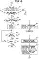
- the CPU 305 executes functions according to a flow chart shown in Fig. 5. At first the CPU 305 analyzes and converts the text data into bit map data of a resolution and a gradation designated as default values and stores such data in the hard disk 303 (S51).
- the CPU 305 inquires, by the asynchronous mode of the IEEE1394 bus, whether the printer 103 is in a printable state.
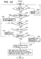
- the printer 103 responds to the inquiry (S52) as shown in S231 in Fig. 23.
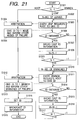
- the CPU 305 discriminates whether the text is printable based on the response from the printer 103, and, if printable, the sequence proceeds to a step S55, but, if not, the sequence to a step S54 (S53).
- the state is displayed on the display 301 and the sequence waits until the printer 103 becomes printable. For example, if the printer 103 is incapable of printing because of lack of paper, the display 301 shows "lack of paper" and the sequence waits until the printer reaches the printable state by the paper replenishment by the user (S54).
- the CPU 305 sends the bit image data to the printer 103 by the isochronous mode of the IEEE1394 bus, and issues a request for isochronous communication to the bus master of the IEEE1394 bus in order to execute the printing operation (S55).
- the sequence awaits the acquisition of the bus band width in response to the request, and, upon acquisition, the sequence proceeds to a next step (S56).
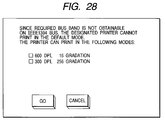
- step S59 starts the printing process, but, if not, a step S58 executes a process to effect printing within the acquired bus band width.
- the necessary bus band width may not always be secured since, on the IEEE1394 bus, the isochronous mode may also be utilized by other apparatus such as a digital camera or a digital video camera.
- the printer is assumed to be a color (CMYK) page printer having a maximum resolution of 600 dpi, a maximum gradation of 256 levels and a printing speed of 15 ppm.
- CYK color
- the printer of the present embodiment constituted by a page printer such as a laser beam printer with a RAM capacity limited to about 512 KB for cost reduction, can store only a part of the image data of a page.
- the printing is executed with a speed of 15 ppm
- the bus band acquired in the arbitration varies in each arbitration, depending on the apparatus connected to the 1394 bus and how such apparatus are used. If many apparatus wish data transfer of a large amount, the bus band width acquirable per apparatus basically becomes narrower.
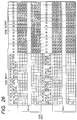
- the printer can select, in addition to the aforementioned mode of receiving the data of 600 dpi and 256 gradation levels, modes of data transfer with a smaller band width, for example a mode of receiving the data at 600 dpi and 16 gradation levels (bus band width being halved to 129 Mbit/s) or a mode of receiving data at 300 dpi and 256 gradation levels (bus band width being reduced to 1/4 or 64 Mbit/s).
- modes of data transfer with a smaller band width for example a mode of receiving the data at 600 dpi and 16 gradation levels (bus band width being halved to 129 Mbit/s) or a mode of receiving data at 300 dpi and 256 gradation levels (bus band width being reduced to 1/4 or 64 Mbit/s).
- the CPU 305 of the PC 101 functions in the following manner in order to effect the printing in the acquired bus band width:
- Fig. 4A shows an example of the format of the transmitted image data (S59) (corresponding to the content of the data field in Fig. 15).
- the compression flag in Fig. 4A is 0.
- the printer 103 decides to use the decompressor 206 or not, according to this compression flag.
- the CPU 204 of the printer 103 changes the operation mode according to the mode setting command supplied from the personal computer, and, stores the image data, transferred from the PC 101 in the isochronous mode of IEEE1394, into the RAM 202 either through the decompressor 203 or directly respectively if the transferred image data are compressed or not, then reads and sends the image data in succession from the RAM 203 to the multivalue-PWM conversion unit 206 for effecting the PWM modulation according to the operation mode, and sends the modulated data through the printer engine I/F 207 to the printer engine 208 for printing.
- the present embodiment allows stable printing even when the IEEE1394 bus is congested, by changing the set mode according to the acquired bus band width.
- the present invention enables the data transfer of an amount corresponding to the data amount of available synchronized transfer. Consequently, the data of a high resolution and a large number of gradation levels are transferred in case a large transferable data amount is secured, but, in case only a smaller transferable data amount can be secured, data can still be securely transferred although the resolution and the number of gradation levels are lowered.
- the present invention is more effective because the transferable data amount is not determined uniquely but is variable according to the magnitude of the acquired bus band width.
- the data of a high resolution and a large number of gradation levels can be sufficiently transferred by data compression
- the invention intends to effect optimum output control according to the data transfer amount (bus band width) per unit time.
- an information processing apparatus featured by identifying the data amount of synchronous transfer transmittable at every predetermined time, judging whether the image data of predetermined image quality can be transmitted within the identified data amount of synchronous transfer, setting the image quality of the image data to be transmitted in case the image data are judged not transmittable and generating the image data to be transmitted, with the set image quality.
Landscapes
- Engineering & Computer Science (AREA)
- Signal Processing (AREA)
- Multimedia (AREA)
- Computer Networks & Wireless Communication (AREA)
- General Engineering & Computer Science (AREA)
- Theoretical Computer Science (AREA)
- Computing Systems (AREA)
- General Physics & Mathematics (AREA)
- Physics & Mathematics (AREA)
- Computer Hardware Design (AREA)
- Computer And Data Communications (AREA)
- Facsimiles In General (AREA)
- Information Transfer Between Computers (AREA)
- Facsimile Transmission Control (AREA)
- Small-Scale Networks (AREA)
- Information Transfer Systems (AREA)
- Communication Control (AREA)
Applications Claiming Priority (3)
| Application Number | Priority Date | Filing Date | Title |
|---|---|---|---|
| JP203213/97 | 1997-07-29 | ||
| JP9203213A JPH1155485A (ja) | 1997-07-29 | 1997-07-29 | 情報処理装置、情報処理方法、及びコンピュータが読み出し可能なプログラムを記憶した記憶媒体 |
| JP20321397 | 1997-07-29 |
Publications (2)
| Publication Number | Publication Date |
|---|---|
| EP0895400A2 true EP0895400A2 (fr) | 1999-02-03 |
| EP0895400A3 EP0895400A3 (fr) | 2001-03-07 |
Family
ID=16470346
Family Applications (1)
| Application Number | Title | Priority Date | Filing Date |
|---|---|---|---|
| EP98114103A Withdrawn EP0895400A3 (fr) | 1997-07-29 | 1998-07-28 | Dispositif et procédé de traitement d'information, et moyen de stockage pour ceux-ci |
Country Status (3)
| Country | Link |
|---|---|
| US (1) | US6580827B2 (fr) |
| EP (1) | EP0895400A3 (fr) |
| JP (1) | JPH1155485A (fr) |
Cited By (5)
| Publication number | Priority date | Publication date | Assignee | Title |
|---|---|---|---|---|
| EP1168187A4 (fr) * | 1999-03-31 | 2003-02-05 | Copyer Co | Procede de communication de serie synchrone et systeme pour communication de serie synchrone |
| EP1047224A3 (fr) * | 1999-04-23 | 2003-04-23 | Matsushita Electric Industrial Co., Ltd. | Moniteur de sécurité de réseau et méthode de surveillance |
| FR2837296A1 (fr) * | 2002-03-15 | 2003-09-19 | Airbus France | Dispositif et procede d'acquisition de mesures a l'aide d'un bus de communication numerique, utilises notamment lors des essais d'un aeronef |
| EP1764704A3 (fr) * | 2005-08-30 | 2007-08-29 | Ricoh Company, Ltd. | Système de traitement d'informations, procédé de transfert de données et produit informatique |
| EP1107103A3 (fr) * | 1999-12-03 | 2007-11-07 | Canon Kabushiki Kaisha | Dispositif électronique et méthode permettant de gérer un support de stockage amovible, et support de stockage correspondant |
Families Citing this family (11)
| Publication number | Priority date | Publication date | Assignee | Title |
|---|---|---|---|---|
| JP3004618B2 (ja) * | 1998-02-27 | 2000-01-31 | キヤノン株式会社 | 画像入力装置及び画像入力システム及び画像送受信システム及び画像入力方法及び記憶媒体 |
| CN100362501C (zh) * | 1998-07-31 | 2008-01-16 | 松下电器产业株式会社 | 用于获得节点编号与终端设备对应关系的计算机 |
| JP3784994B2 (ja) * | 1999-05-27 | 2006-06-14 | 株式会社東芝 | データ処理装置 |
| US7216157B1 (en) * | 1999-06-10 | 2007-05-08 | Verizonbusinessgloballlc | Method and system for discovering managed devices in a data network |
| JP3767330B2 (ja) * | 2000-06-19 | 2006-04-19 | Kddi株式会社 | 帯域共有制御システム |
| DE10145708B4 (de) * | 2000-09-19 | 2007-02-01 | Samsung Electronics Co., Ltd., Suwon | Vorrichtung und Verfahren zum Verbinden eines Basismoduls mit einem Funktionserweiterungsmodul in einem AV-System |
| US7417973B1 (en) * | 2002-12-31 | 2008-08-26 | Apple Inc. | Method, apparatus and computer program product for ensuring node participation in a network bus |
| JP2007030248A (ja) * | 2005-07-25 | 2007-02-08 | Brother Ind Ltd | 画像処理装置 |
| US10484732B2 (en) * | 2015-12-29 | 2019-11-19 | Tv One Limited | Data processing backplane with serial bus communication loop |
| JP2018137547A (ja) * | 2017-02-20 | 2018-08-30 | 株式会社東芝 | 情報処理装置及び画像形成装置 |
| TWI768992B (zh) * | 2021-06-30 | 2022-06-21 | 創惟科技股份有限公司 | 高速傳輸系統、訊號中繼器以及訊號中繼器的控制方法 |
Family Cites Families (4)
| Publication number | Priority date | Publication date | Assignee | Title |
|---|---|---|---|---|
| US5572335A (en) * | 1994-04-01 | 1996-11-05 | Xerox Corporation | Method and system for transferring image data between two devices having different bandwidths |
| DE69510403T2 (de) * | 1994-04-18 | 1999-11-25 | Canon K.K., Tokio/Tokyo | Datenübertragungsgerät, -verfahren und -system |
| US5933430A (en) * | 1995-08-12 | 1999-08-03 | Sony Corporation | Data communication method |
| JPH09244830A (ja) * | 1996-03-13 | 1997-09-19 | Canon Inc | 画像処理システム及び画像処理システム制御方法 |
-
1997
- 1997-07-29 JP JP9203213A patent/JPH1155485A/ja not_active Withdrawn
-
1998
- 1998-07-28 EP EP98114103A patent/EP0895400A3/fr not_active Withdrawn
- 1998-07-29 US US09/124,020 patent/US6580827B2/en not_active Expired - Fee Related
Cited By (9)
| Publication number | Priority date | Publication date | Assignee | Title |
|---|---|---|---|---|
| EP1168187A4 (fr) * | 1999-03-31 | 2003-02-05 | Copyer Co | Procede de communication de serie synchrone et systeme pour communication de serie synchrone |
| US7184501B1 (en) | 1999-03-31 | 2007-02-27 | Canon Finetech Inc. | Method of synchronous serial communication and system for synchronous serial communication |
| EP1047224A3 (fr) * | 1999-04-23 | 2003-04-23 | Matsushita Electric Industrial Co., Ltd. | Moniteur de sécurité de réseau et méthode de surveillance |
| EP1107103A3 (fr) * | 1999-12-03 | 2007-11-07 | Canon Kabushiki Kaisha | Dispositif électronique et méthode permettant de gérer un support de stockage amovible, et support de stockage correspondant |
| FR2837296A1 (fr) * | 2002-03-15 | 2003-09-19 | Airbus France | Dispositif et procede d'acquisition de mesures a l'aide d'un bus de communication numerique, utilises notamment lors des essais d'un aeronef |
| US6937957B2 (en) | 2002-03-15 | 2005-08-30 | Airbus France | Device and process for acquisition of measurements using a digital communication bus, particularly used during aircraft tests |
| US7072803B2 (en) | 2002-03-15 | 2006-07-04 | Airbus France | Device and process for acquisition of measurements using a digital communication bus, particularly used during aircraft tests |
| EP1764704A3 (fr) * | 2005-08-30 | 2007-08-29 | Ricoh Company, Ltd. | Système de traitement d'informations, procédé de transfert de données et produit informatique |
| US7536489B2 (en) | 2005-08-30 | 2009-05-19 | Ricoh Company Limited | Information processing system for determining payload size based on packet-to-payload size ratio |
Also Published As
| Publication number | Publication date |
|---|---|
| US6580827B2 (en) | 2003-06-17 |
| JPH1155485A (ja) | 1999-02-26 |
| US20020057448A1 (en) | 2002-05-16 |
| EP0895400A3 (fr) | 2001-03-07 |
Similar Documents
| Publication | Publication Date | Title |
|---|---|---|
| US6334161B1 (en) | System for reverse data transmission flow control wherein command is transferred by asynchronous transfer mode while data is transferred by isochronous transfer mode | |
| US7062579B2 (en) | Data transmission apparatus, system and method, and image processing apparatus | |
| US7213138B2 (en) | Data transmission apparatus, system and method, and image processing apparatus | |
| EP0895400A2 (fr) | Dispositif et procédé de traitement d'information, et moyen de stockage pour ceux-ci | |
| CA2229472C (fr) | Appareil et methode de transmission de donnees | |
| US6711637B2 (en) | Communication apparatus, image processing apparatus, communication system, communication method, image processing method and storage medium | |
| US6603737B1 (en) | Data transmission apparatus, system and method, and image processing apparatus | |
| US7050184B1 (en) | Data transfer apparatus and method, and data transfer system and medium | |
| JP2000050241A (ja) | 撮像装置システム及びその制御方法及び撮像装置及び制御装置及び撮像装置における制御方法及び制御装置における制御方法及び記憶媒体 | |
| JP2002074350A (ja) | 画像処理システム及びその制御方法、及び画像処理装置 | |
| JP2001275066A (ja) | 画像処理装置およびその方法、並びに、記憶媒体 | |
| JP3943722B2 (ja) | データ転送装置、データ転送システムおよびその方法、画像処理装置、並びに、記録媒体 | |
| JPH10229538A (ja) | データ通信システム、プリントシステム及びデータ通信装置 | |
| JPH11110160A (ja) | 印刷制御装置及び印刷制御方法 | |
| JP2002016750A (ja) | 画像形成装置及びその制御方法と画像形成システム | |
| JP3647328B2 (ja) | 画像処理装置及びその制御方法並びに画像処理システム | |
| US7397574B1 (en) | Image processing controlling distribution of work among apparatuses based on apparatus performance | |
| JPH10228364A (ja) | データ転送装置及びその制御方法及び印刷システム | |
| JPH11282645A (ja) | 画像形成システムと印刷制御装置及び方法 | |
| JP2004030109A (ja) | 情報処理装置、情報処理方法及びそのプログラムを記憶した記憶媒体 | |
| AU762552B2 (en) | Data communication apparatus and method | |
| JPH10307691A (ja) | データ通信方法と装置及び印刷装置と前記装置を含む印刷システム | |
| JP2000261468A (ja) | ネットワーク接続装置及びネットワーク接続方法 | |
| JPH11196108A (ja) | 画像データ転送補償処理方法及び装置 | |
| JP2000172470A (ja) | 印刷制御装置及び方法 |
Legal Events
| Date | Code | Title | Description |
|---|---|---|---|
| PUAI | Public reference made under article 153(3) epc to a published international application that has entered the european phase |
Free format text: ORIGINAL CODE: 0009012 |
|
| AK | Designated contracting states |
Kind code of ref document: A2 Designated state(s): AT BE CH CY DE DK ES FI FR GB GR IE IT LI LU MC NL PT SE |
|
| AX | Request for extension of the european patent |
Free format text: AL;LT;LV;MK;RO;SI |
|
| PUAL | Search report despatched |
Free format text: ORIGINAL CODE: 0009013 |
|
| AK | Designated contracting states |
Kind code of ref document: A3 Designated state(s): AT BE CH CY DE DK ES FI FR GB GR IE IT LI LU MC NL PT SE |
|
| AX | Request for extension of the european patent |
Free format text: AL;LT;LV;MK;RO;SI |
|
| 17P | Request for examination filed |
Effective date: 20010720 |
|
| AKX | Designation fees paid |
Free format text: DE FR GB IT NL |
|
| 17Q | First examination report despatched |
Effective date: 20050629 |
|
| GRAP | Despatch of communication of intention to grant a patent |
Free format text: ORIGINAL CODE: EPIDOSNIGR1 |
|
| STAA | Information on the status of an ep patent application or granted ep patent |
Free format text: STATUS: THE APPLICATION HAS BEEN WITHDRAWN |
|
| 18W | Application withdrawn |
Effective date: 20091214 |