EP0895909A2 - Selbsttätige Nachstellvorrichtung für Handbremshebeln - Google Patents
Selbsttätige Nachstellvorrichtung für Handbremshebeln Download PDFInfo
- Publication number
- EP0895909A2 EP0895909A2 EP98500144A EP98500144A EP0895909A2 EP 0895909 A2 EP0895909 A2 EP 0895909A2 EP 98500144 A EP98500144 A EP 98500144A EP 98500144 A EP98500144 A EP 98500144A EP 0895909 A2 EP0895909 A2 EP 0895909A2
- Authority
- EP
- European Patent Office
- Prior art keywords
- hand brake
- casing
- tensioning device
- slide
- automatic tensioning
- Prior art date
- Legal status (The legal status is an assumption and is not a legal conclusion. Google has not performed a legal analysis and makes no representation as to the accuracy of the status listed.)
- Granted
Links
- 230000001105 regulatory effect Effects 0.000 claims description 3
- 239000000470 constituent Substances 0.000 description 3
- 238000010276 construction Methods 0.000 description 2
- 230000015572 biosynthetic process Effects 0.000 description 1
- 230000007423 decrease Effects 0.000 description 1
- 239000000463 material Substances 0.000 description 1
- 238000000034 method Methods 0.000 description 1
Images
Classifications
-
- B—PERFORMING OPERATIONS; TRANSPORTING
- B60—VEHICLES IN GENERAL
- B60T—VEHICLE BRAKE CONTROL SYSTEMS OR PARTS THEREOF; BRAKE CONTROL SYSTEMS OR PARTS THEREOF, IN GENERAL; ARRANGEMENT OF BRAKING ELEMENTS ON VEHICLES IN GENERAL; PORTABLE DEVICES FOR PREVENTING UNWANTED MOVEMENT OF VEHICLES; VEHICLE MODIFICATIONS TO FACILITATE COOLING OF BRAKES
- B60T7/00—Brake-action initiating means
- B60T7/02—Brake-action initiating means for personal initiation
- B60T7/08—Brake-action initiating means for personal initiation hand actuated
- B60T7/10—Disposition of hand control
- B60T7/108—Disposition of hand control with mechanisms to take up slack in the linkage to the brakes
-
- Y—GENERAL TAGGING OF NEW TECHNOLOGICAL DEVELOPMENTS; GENERAL TAGGING OF CROSS-SECTIONAL TECHNOLOGIES SPANNING OVER SEVERAL SECTIONS OF THE IPC; TECHNICAL SUBJECTS COVERED BY FORMER USPC CROSS-REFERENCE ART COLLECTIONS [XRACs] AND DIGESTS
- Y10—TECHNICAL SUBJECTS COVERED BY FORMER USPC
- Y10T—TECHNICAL SUBJECTS COVERED BY FORMER US CLASSIFICATION
- Y10T74/00—Machine element or mechanism
- Y10T74/20—Control lever and linkage systems
- Y10T74/20396—Hand operated
- Y10T74/20402—Flexible transmitter [e.g., Bowden cable]
- Y10T74/20408—Constant tension sustaining
-
- Y—GENERAL TAGGING OF NEW TECHNOLOGICAL DEVELOPMENTS; GENERAL TAGGING OF CROSS-SECTIONAL TECHNOLOGIES SPANNING OVER SEVERAL SECTIONS OF THE IPC; TECHNICAL SUBJECTS COVERED BY FORMER USPC CROSS-REFERENCE ART COLLECTIONS [XRACs] AND DIGESTS
- Y10—TECHNICAL SUBJECTS COVERED BY FORMER USPC
- Y10T—TECHNICAL SUBJECTS COVERED BY FORMER US CLASSIFICATION
- Y10T74/00—Machine element or mechanism
- Y10T74/20—Control lever and linkage systems
- Y10T74/20396—Hand operated
- Y10T74/20402—Flexible transmitter [e.g., Bowden cable]
- Y10T74/2045—Flexible transmitter [e.g., Bowden cable] and sheath support, connector, or anchor
Definitions
- This invention relates to an automatic tensioning device for the hand brake levers of automobile vehicles, whose purpose is to keep the brake cable properly tensioned. These cables go from the position of the said lever to the braking elements, the brake shoes of the vehicle wheels. In the same way, its application in other techniques that require a cable to be kept under tension is not discarded.
- the EP.A. 0040574 also uses a toothed central part in association with tow other toothed side parts.
- these two side parts have chamfers that rest on the inclined surfaces of a front part, with these side pieces in turn being forced by a spring that surrounds the central part and butts up against a rear cover fixed to this central part.
- One object is to provide an automatic tensioning device for hand brake levers that is extraordinarily simple.
- Another object of the invention is an automatic tensioning device for hand brake levers that provides a very sturdy system with a long working life.
- Another object of the invention is an automatic tensioning device for hand brake levers that offers very easy assembly and versatility, as it can be positioned in different locations in the system.
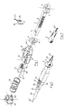
- the device in the invention claims a longitudinal casing or frame which is hollow inside and has a rectangular shape, that has one open end and has its other end tapered by having converging side walls of the cross section, and is also open towards the exterior.
- the first opening has a bigger cross section than the second.
- Running through the axial centre of this casing is a part by way of a slide, which has a square transversal cross section and is provided with vertically-cut teeth on its sides, at the end corresponding to the tapered part of the casing.
- the cross section of this slide is such that it is able to pass through the gap in the converging end of the casing.
- the end of the slide at the end corresponding to the wider part of the casing, is provided with a set of notches cut into two of its parallel sides, and the end is provided with means to receive the tension cables that are connected to the brake shoes.
- the portion of the slide that is provided with these notches is surrounded by a spring that becomes housed inside the casing and controlled by a rear cover that closes off the open end of the said casing.
- This cover is provided with two lugs that project inwards, whose ends have ridges that are capable of fitting into the notches in the slide, so that this cover, apart from closing off the end of the casing, acts as a support for the spring that surrounds the slide.
- the inside of the casing is also occupied by another two longitudinal parts with a square cross section that are located at the sides of the slide, with these side pieces having vertically-cut teeth on their sides towards the slide, that correspond with those on the said slide.
- the ends of these two longitudinal parts are wedge-shaped along the sides of their outer ends, through which they adapt to the converging inner sides of the casing.
- the open converging end of this casing also receives another cover provided with a square central hole, through which the slide passes.
- the inner side of this cover is provided with projections that also pass through the opening in the casing and provide frontal support for the two previously mentioned longitudinal parts and, at the same time, are used to unlock these in resetting the mechanism to zero, as will be explained later.
- a U-shaped fork is situated in front of this cover, with its wings or sides provided with vertical facing ledges capable of being housed between the teeth of the protruding portion of the slide, thus fixing the latter in the initial pretensioning position of the unit.
- the protruding forward end of the slide can be connected directly to the tensioning cable through a hole in the said end, which is usually inclined in relation to the rest of the slide.
- the protruding forward end of the slide can also be connected to a balance lever, from which the cables leave that go to the brake shoes.
- the unit of the device can be assembled on the hand brake base or support, by means of a pin that passes through a set of lugs with holes that form part of the casing itself.
- the unit can also be assembled on a rod or cable protruding from the hand brake lever itself, based on a prolongation that starts from the casing in the position of the cover that controls the internal spring.
- the unit of the device can be assembled on any cable, rod or tension member that is capable of being regulated.
- the operation of the automatic tensioning device begins with the setting of the tensioning of the cable by using the fork in order to carry out this setting.
- the fork is connected by any known or conventional means to the hand brake lever in such a way that when the lever is initially operated, the fork is extracted from its pretensioning position.
- the casing or frame (9) open at its rear end (12) and with its forward end (24) with converging side walls also open.
- the casing (9) has its lugs (11), holed and facing each other, capable of receiving a pin or shaft for it to be fitted onto the hand brake lever base or support.
- the lugs (18) finish off in ridges that are received in the two notches (3) in the slide (2), thus fixing the mutual position of both parts, and the two longitudinal parts (13, 14) have the teeth (15) cut in their facing sides, as well as the outer chamfers (23) for them to adapt to the converging side walls of the casing (9).
- the forward cover (6) that closes off the forward end (24) of the casing (9) has a central hole (8) through which the slide (2) passes, as do the rear lugs, not numbered, that become housed in the casing (9) as will be appreciated later.
- the U-shaped fork (19) can be seen, with its wings (20) provided with vertical facing ledges (21) responsible for becoming housed between the teeth (1) of the said slide in order to set the zero resetting position of the unit.
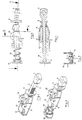
- This fork is situated in front of the forwards cover (6) in this operation, and has a prolongation (22) that is connected to the hand brake lever, so that when the hand brake lever begins its successive operations, the fork can be removed without being lost and with the possibility of being reusable.
- the fork is already removed and the device is assembled, pretensioned and prepared to carry out its function of automatically regulating the tension of the cable that goes from the end (4) of the slide towards the brake shoes of the wheels.
- the inclination of the end or head (4) of the slide (2) is advisable when a balance lever is used, with two tensioning cables being connected to this balance lever, for example, so that the theoretical longitudinal prolongation of this end (4) passes through the centre of the holes (10) in the lugs (11) on the casing (9) in order to avoid maladjustment in assembly.
- Figures 5 and 6 allow us to observe the entry of the two longitudinal parts (13, 14) to the base of the forwards converging area of the casing (9), duly, obliged by the spring (16) and putting pressure on the slide (2) by the engagement of the respective teeth.
- Figure 7 shows the construction variant, according to which the device is mounted on a cable or rod (24') that protrudes from the hand brake lever.
- the casing or frame is modified at the rear portion (25,26,27,28) in order to connect it to the said cable or rod (24'), all with the forward portion determined by the formation (23) connected to the cable (24) at the forward end of the slide (2), which is shown enlarged in Figure 8.
Landscapes
- Engineering & Computer Science (AREA)
- Transportation (AREA)
- Mechanical Engineering (AREA)
- Braking Arrangements (AREA)
- Transmission Of Braking Force In Braking Systems (AREA)
- Mechanical Control Devices (AREA)
Applications Claiming Priority (2)
| Application Number | Priority Date | Filing Date | Title |
|---|---|---|---|
| ES009701337A ES2141659B1 (es) | 1997-06-19 | 1997-06-19 | Dispositivo de autotensado para palancas de freno de mano. |
| ES9701337 | 1997-06-19 |
Publications (3)
| Publication Number | Publication Date |
|---|---|
| EP0895909A2 true EP0895909A2 (de) | 1999-02-10 |
| EP0895909A3 EP0895909A3 (de) | 1999-04-21 |
| EP0895909B1 EP0895909B1 (de) | 2002-10-09 |
Family
ID=8299732
Family Applications (1)
| Application Number | Title | Priority Date | Filing Date |
|---|---|---|---|
| EP98500144A Expired - Lifetime EP0895909B1 (de) | 1997-06-19 | 1998-06-19 | Selbsttätige Nachstellvorrichtung für Handbremshebeln |
Country Status (5)
| Country | Link |
|---|---|
| US (1) | US6023992A (de) |
| EP (1) | EP0895909B1 (de) |
| BR (1) | BR9804184A (de) |
| DE (1) | DE69808572T2 (de) |
| ES (2) | ES2141659B1 (de) |
Cited By (3)
| Publication number | Priority date | Publication date | Assignee | Title |
|---|---|---|---|---|
| WO2001053709A1 (es) * | 2000-01-20 | 2001-07-26 | Batz, S. Coop. | Tensor para cables de freno |
| FR2805508A1 (fr) * | 2000-02-24 | 2001-08-31 | Rapid Sa | Procede de montage d'un agencement, tel qu'un frein a main, et ensemble pour la mise en oeuvre du procede |
| WO2002070311A3 (de) * | 2001-03-02 | 2003-02-06 | Edscha Ag | Seilzugnachstellung für eine feststellbremse |
Families Citing this family (10)
| Publication number | Priority date | Publication date | Assignee | Title |
|---|---|---|---|---|
| WO2007026208A2 (en) * | 2005-08-29 | 2007-03-08 | Ventra Group Inc. | Brake tension monitoring assembly and method |
| US7475615B2 (en) * | 2006-06-05 | 2009-01-13 | Ventra Group Inc. | Self-adjusting parking brake actuator for vehicles |
| US8215202B2 (en) * | 2007-06-18 | 2012-07-10 | Grand Rapids Controls Company, Llc | Cable length adjustment mechanism |
| DE202008000220U1 (de) * | 2008-01-07 | 2009-05-28 | Al-Ko Kober Ag | Montagehilfe |
| US20110030497A1 (en) * | 2008-04-17 | 2011-02-10 | Nebojsa Djordjevic | Self-adjust mechanism for parking brake assembly |
| KR101031065B1 (ko) * | 2008-06-18 | 2011-04-25 | 에스엘 주식회사 | 주차 브레이크에서의 케이블 장력 자동 조정 장치 및 이를이용한 주차 브레이크 장치 |
| US20100275715A1 (en) * | 2009-05-01 | 2010-11-04 | Dura Global Technologies, Inc. | Shift cable assembly and connector therefor |
| US8381613B2 (en) * | 2010-07-08 | 2013-02-26 | Ventra Group, Inc. | Parking brake cable and adjust system having no lost cable travel |
| US8690109B2 (en) | 2011-08-03 | 2014-04-08 | Haworth, Inc. | Automatic gap adjustor |
| ES2425005B1 (es) * | 2012-04-04 | 2015-02-17 | Batz, S.Coop. | Dispositivo de autotensado de un cable adaptado a frenos de estacionamiento y freno de estacionamiento con el dispositivo de autotensado |
Citations (2)
| Publication number | Priority date | Publication date | Assignee | Title |
|---|---|---|---|---|
| US1741365A (en) | 1927-06-11 | 1929-12-31 | Heymann Edward | Brake mechanism |
| EP0040574A1 (de) | 1980-05-19 | 1981-11-25 | PAUMELLERIE ELECTRIQUE Société dite: | Betätigungsvorrichtung für die Handbremse |
Family Cites Families (9)
| Publication number | Priority date | Publication date | Assignee | Title |
|---|---|---|---|---|
| JPH0130655Y2 (de) * | 1985-06-19 | 1989-09-20 | ||
| FR2621090A1 (fr) * | 1987-09-29 | 1989-03-31 | Kuczynski Grzegorz Robert | Dispositif pour reglage automatique de position du levier de frein a main d'un vehicule |
| JP2571795B2 (ja) * | 1987-11-17 | 1997-01-16 | 住友電気工業株式会社 | 紫色ダイヤモンドおよびその製造方法 |
| JP2839711B2 (ja) * | 1992-05-07 | 1998-12-16 | キュスター ウント コンパニー ゲゼルシャフト ミット ベシュレンクテル ハフツング | 機械的なフレキシブルな遠隔操作手段の長さ修正装置 |
| ES2089652T3 (es) * | 1992-08-12 | 1996-10-01 | Kuester & Co Gmbh | Dispositivo de ajuste para frenos, especialmente para frenos de vehiculos. |
| JPH06147215A (ja) * | 1992-10-31 | 1994-05-27 | Nhk Spring Co Ltd | コントロールケーブルの長さ調整装置 |
| DE9405849U1 (de) * | 1994-04-08 | 1995-05-18 | AL-KO Kober AG, 89359 Kötz | Feststellbremse für Kraftfahrzeuge, Fahrzeuganhänger o.dgl. |
| US5485762A (en) * | 1994-06-20 | 1996-01-23 | Hi-Shear Corporation | Adjuster to establish and maintain residual tension in a cable system |
| DE19618422C2 (de) * | 1995-11-20 | 1999-11-11 | Kuester & Co Gmbh | Vorrichtung zur selbsttätigen Längenkorrektur von Seilzügen |
-
1997
- 1997-06-19 ES ES009701337A patent/ES2141659B1/es not_active Expired - Fee Related
-
1998
- 1998-06-17 US US09/098,378 patent/US6023992A/en not_active Expired - Fee Related
- 1998-06-19 EP EP98500144A patent/EP0895909B1/de not_active Expired - Lifetime
- 1998-06-19 ES ES98500144T patent/ES2185134T3/es not_active Expired - Lifetime
- 1998-06-19 DE DE69808572T patent/DE69808572T2/de not_active Expired - Lifetime
- 1998-06-19 BR BR9804184-3A patent/BR9804184A/pt not_active IP Right Cessation
Patent Citations (2)
| Publication number | Priority date | Publication date | Assignee | Title |
|---|---|---|---|---|
| US1741365A (en) | 1927-06-11 | 1929-12-31 | Heymann Edward | Brake mechanism |
| EP0040574A1 (de) | 1980-05-19 | 1981-11-25 | PAUMELLERIE ELECTRIQUE Société dite: | Betätigungsvorrichtung für die Handbremse |
Cited By (6)
| Publication number | Priority date | Publication date | Assignee | Title |
|---|---|---|---|---|
| WO2001053709A1 (es) * | 2000-01-20 | 2001-07-26 | Batz, S. Coop. | Tensor para cables de freno |
| ES2160537A1 (es) * | 2000-01-20 | 2001-11-01 | Batz S Coop | Tensor para cables de freno de mano. |
| FR2805508A1 (fr) * | 2000-02-24 | 2001-08-31 | Rapid Sa | Procede de montage d'un agencement, tel qu'un frein a main, et ensemble pour la mise en oeuvre du procede |
| EP1134136A1 (de) * | 2000-02-24 | 2001-09-19 | Rapid S.A. | Montageverfahren für eine Handbremse und Vorrichtung zur Durchführung des Verfahrens |
| WO2002070311A3 (de) * | 2001-03-02 | 2003-02-06 | Edscha Ag | Seilzugnachstellung für eine feststellbremse |
| US7146873B2 (en) | 2001-03-02 | 2006-12-12 | Edscha Betaetigungssysteme Gmbh | Cable pull adjustment for a parking brake |
Also Published As
| Publication number | Publication date |
|---|---|
| EP0895909B1 (de) | 2002-10-09 |
| ES2141659A1 (es) | 2000-03-16 |
| US6023992A (en) | 2000-02-15 |
| ES2141659B1 (es) | 2000-11-16 |
| BR9804184A (pt) | 1999-12-14 |
| ES2185134T3 (es) | 2003-04-16 |
| DE69808572D1 (de) | 2002-11-14 |
| DE69808572T2 (de) | 2003-09-18 |
| EP0895909A3 (de) | 1999-04-21 |
Similar Documents
| Publication | Publication Date | Title |
|---|---|---|
| EP0895909B1 (de) | Selbsttätige Nachstellvorrichtung für Handbremshebeln | |
| US20190176870A1 (en) | Steering column for a motor vehicle | |
| DE4340633C2 (de) | Rückholsystem für das Pedalsystem und/oder die Lenksäule von Kfz. | |
| US5448928A (en) | Variable ratio parking brake lever with self-adjust cable tensioning means | |
| ES2277661T3 (es) | Dispositivo de pedales retractable en caso de impacto frontal con un vehiculo. | |
| HUE029834T2 (en) | Inside collapsible steering column unit | |
| EP0440698A1 (de) | Höhenverstellbare und längenverschiebliche lenksäule. | |
| EP0568996B1 (de) | Linearantrieb für einen Gurtstraffer | |
| AU711315B2 (en) | Parking brake for motor vehicles, towed vehicles, or suchlike | |
| CA2326150A1 (en) | Steering wheel impact positioning system | |
| US4532824A (en) | Automobile automatic transmission control device | |
| US6264228B1 (en) | Hitch assembly for activating a towed vehicle's brakes | |
| GB1573896A (en) | Slide for a vehicle seat particularly for seat of an automobile vehicle | |
| GB1569095A (en) | Lock for anchoring a vehicle cab of the tippable type | |
| EP0556169A1 (de) | Runge für eine Fahrzeug-Ladeplattform | |
| FR2595643A1 (fr) | Modulateur de pression a commande electro-magnetique | |
| MXPA98004912A (en) | Automotive device for fr levers | |
| DE4322796C2 (de) | Mechanischer Beschleunigungssensor | |
| DE3937218A1 (de) | Mechanischer tuerfeststeller fuer kraftwagentueren | |
| DE19629263A1 (de) | Gurtstrammer für Sicherheitsgurte | |
| FR2786737A1 (fr) | Dispositif pour le montage d'une pedale | |
| EP1398233A2 (de) | Bremseinrichtung für Fahrzeuganhänger mit Nachstelleinrichtung | |
| FR3043971A1 (fr) | Palonnier de frein de stationnement de vehicule automobile | |
| EP0045240B1 (de) | Einrichtung zur selbsttätigen Freigabe der Sicherheitsgurthalterung für Kraftwagen am Wagenaufbau | |
| RU2078703C1 (ru) | Устройство экстренного торможения транспортного средства |
Legal Events
| Date | Code | Title | Description |
|---|---|---|---|
| PUAI | Public reference made under article 153(3) epc to a published international application that has entered the european phase |
Free format text: ORIGINAL CODE: 0009012 |
|
| AK | Designated contracting states |
Kind code of ref document: A2 Designated state(s): DE ES FI GB IT SE |
|
| AX | Request for extension of the european patent |
Free format text: AL;LT;LV;MK;RO;SI |
|
| PUAL | Search report despatched |
Free format text: ORIGINAL CODE: 0009013 |
|
| AK | Designated contracting states |
Kind code of ref document: A3 Designated state(s): AT BE CH CY DE DK ES FI FR GB GR IE IT LI LU MC NL PT SE |
|
| AX | Request for extension of the european patent |
Free format text: AL;LT;LV;MK;RO;SI |
|
| AKX | Designation fees paid |
Free format text: DE ES FI GB IT SE |
|
| 17P | Request for examination filed |
Effective date: 20000105 |
|
| EUG | Se: european patent has lapsed | ||
| GRAG | Despatch of communication of intention to grant |
Free format text: ORIGINAL CODE: EPIDOS AGRA |
|
| 17Q | First examination report despatched |
Effective date: 20020605 |
|
| GRAG | Despatch of communication of intention to grant |
Free format text: ORIGINAL CODE: EPIDOS AGRA |
|
| GRAH | Despatch of communication of intention to grant a patent |
Free format text: ORIGINAL CODE: EPIDOS IGRA |
|
| GRAH | Despatch of communication of intention to grant a patent |
Free format text: ORIGINAL CODE: EPIDOS IGRA |
|
| GRAA | (expected) grant |
Free format text: ORIGINAL CODE: 0009210 |
|
| AK | Designated contracting states |
Kind code of ref document: B1 Designated state(s): DE ES FI GB IT SE |
|
| PG25 | Lapsed in a contracting state [announced via postgrant information from national office to epo] |
Ref country code: FI Free format text: LAPSE BECAUSE OF FAILURE TO SUBMIT A TRANSLATION OF THE DESCRIPTION OR TO PAY THE FEE WITHIN THE PRESCRIBED TIME-LIMIT Effective date: 20021009 |
|
| REG | Reference to a national code |
Ref country code: GB Ref legal event code: FG4D |
|
| REF | Corresponds to: |
Ref document number: 69808572 Country of ref document: DE Date of ref document: 20021114 |
|
| REG | Reference to a national code |
Ref country code: ES Ref legal event code: FG2A Ref document number: 2185134 Country of ref document: ES Kind code of ref document: T3 |
|
| PLBE | No opposition filed within time limit |
Free format text: ORIGINAL CODE: 0009261 |
|
| STAA | Information on the status of an ep patent application or granted ep patent |
Free format text: STATUS: NO OPPOSITION FILED WITHIN TIME LIMIT |
|
| 26N | No opposition filed |
Effective date: 20030710 |
|
| PGFP | Annual fee paid to national office [announced via postgrant information from national office to epo] |
Ref country code: SE Payment date: 20060616 Year of fee payment: 9 |
|
| PGFP | Annual fee paid to national office [announced via postgrant information from national office to epo] |
Ref country code: GB Payment date: 20060619 Year of fee payment: 9 |
|
| PGFP | Annual fee paid to national office [announced via postgrant information from national office to epo] |
Ref country code: IT Payment date: 20060630 Year of fee payment: 9 |
|
| EUG | Se: european patent has lapsed | ||
| GBPC | Gb: european patent ceased through non-payment of renewal fee |
Effective date: 20070619 |
|
| PG25 | Lapsed in a contracting state [announced via postgrant information from national office to epo] |
Ref country code: GB Free format text: LAPSE BECAUSE OF NON-PAYMENT OF DUE FEES Effective date: 20070619 |
|
| PG25 | Lapsed in a contracting state [announced via postgrant information from national office to epo] |
Ref country code: SE Free format text: LAPSE BECAUSE OF NON-PAYMENT OF DUE FEES Effective date: 20070620 |
|
| PG25 | Lapsed in a contracting state [announced via postgrant information from national office to epo] |
Ref country code: IT Free format text: LAPSE BECAUSE OF NON-PAYMENT OF DUE FEES Effective date: 20070619 |
|
| PGFP | Annual fee paid to national office [announced via postgrant information from national office to epo] |
Ref country code: ES Payment date: 20100609 Year of fee payment: 13 |
|
| PGFP | Annual fee paid to national office [announced via postgrant information from national office to epo] |
Ref country code: DE Payment date: 20100625 Year of fee payment: 13 |
|
| REG | Reference to a national code |
Ref country code: DE Ref legal event code: R119 Ref document number: 69808572 Country of ref document: DE Effective date: 20120103 |
|
| PG25 | Lapsed in a contracting state [announced via postgrant information from national office to epo] |
Ref country code: DE Free format text: LAPSE BECAUSE OF NON-PAYMENT OF DUE FEES Effective date: 20120103 |
|
| REG | Reference to a national code |
Ref country code: ES Ref legal event code: FD2A Effective date: 20120717 |
|
| PG25 | Lapsed in a contracting state [announced via postgrant information from national office to epo] |
Ref country code: ES Free format text: LAPSE BECAUSE OF NON-PAYMENT OF DUE FEES Effective date: 20110620 |