EP0896096B1 - Verfahren zur Verankerung einer Schichtholzplatte im Boden, und damit hergestellte Baukonstruktion - Google Patents
Verfahren zur Verankerung einer Schichtholzplatte im Boden, und damit hergestellte Baukonstruktion Download PDFInfo
- Publication number
- EP0896096B1 EP0896096B1 EP98111017A EP98111017A EP0896096B1 EP 0896096 B1 EP0896096 B1 EP 0896096B1 EP 98111017 A EP98111017 A EP 98111017A EP 98111017 A EP98111017 A EP 98111017A EP 0896096 B1 EP0896096 B1 EP 0896096B1
- Authority
- EP
- European Patent Office
- Prior art keywords
- wood
- layers
- wooden panel
- laminated wooden
- anchoring
- Prior art date
- Legal status (The legal status is an assumption and is not a legal conclusion. Google has not performed a legal analysis and makes no representation as to the accuracy of the status listed.)
- Expired - Lifetime
Links
Images


Classifications
-
- E—FIXED CONSTRUCTIONS
- E01—CONSTRUCTION OF ROADS, RAILWAYS, OR BRIDGES
- E01F—ADDITIONAL WORK, SUCH AS EQUIPPING ROADS OR THE CONSTRUCTION OF PLATFORMS, HELICOPTER LANDING STAGES, SIGNS, SNOW FENCES, OR THE LIKE
- E01F8/00—Arrangements for absorbing or reflecting air-transmitted noise from road or railway traffic
- E01F8/0005—Arrangements for absorbing or reflecting air-transmitted noise from road or railway traffic used in a wall type arrangement
- E01F8/0047—Arrangements for absorbing or reflecting air-transmitted noise from road or railway traffic used in a wall type arrangement with open cavities, e.g. for covering sunken roads
- E01F8/0052—Grate-style, e.g. as wall facing
- E01F8/0058—Grate-style, e.g. as wall facing with damping material, e.g. rockwool, sand
-
- E—FIXED CONSTRUCTIONS
- E01—CONSTRUCTION OF ROADS, RAILWAYS, OR BRIDGES
- E01F—ADDITIONAL WORK, SUCH AS EQUIPPING ROADS OR THE CONSTRUCTION OF PLATFORMS, HELICOPTER LANDING STAGES, SIGNS, SNOW FENCES, OR THE LIKE
- E01F8/00—Arrangements for absorbing or reflecting air-transmitted noise from road or railway traffic
- E01F8/0005—Arrangements for absorbing or reflecting air-transmitted noise from road or railway traffic used in a wall type arrangement
- E01F8/0017—Plate-like elements
-
- E—FIXED CONSTRUCTIONS
- E01—CONSTRUCTION OF ROADS, RAILWAYS, OR BRIDGES
- E01F—ADDITIONAL WORK, SUCH AS EQUIPPING ROADS OR THE CONSTRUCTION OF PLATFORMS, HELICOPTER LANDING STAGES, SIGNS, SNOW FENCES, OR THE LIKE
- E01F8/00—Arrangements for absorbing or reflecting air-transmitted noise from road or railway traffic
- E01F8/0005—Arrangements for absorbing or reflecting air-transmitted noise from road or railway traffic used in a wall type arrangement
- E01F8/0023—Details, e.g. foundations
Definitions
- the invention relates to a method for erecting a wall of a Building construction, in which at least one tabular wall element Wood vertically with a wall surface area towering above the ground is anchored and anchored to the ground by anchoring means, which in be embedded in the floor and on the wall surface area across the Record wall plane of the wall element acting forces and in the Derive soil, as well as such a construction.
- wood-based materials are recommended for the construction sector because of environmental pollution are not too current.
- wood is considered by many people Material perceived, the buildings a well-being enhancing Gives comfort.
- wood is suitable because of its light weight Machinability, its outstanding building physical and mechanical Properties with appropriate design of wooden components, such as in shape plywood boards, and its weather resistance appropriate impregnation to a high degree as a material for production construction parts for the construction sector.
- statically articulated attachment of wooden supports on a foundation requires additional stiffening measures, for example by a stiffening wall plate, thus a static rigid building construction can be created in which the Clamping moments and forces caught in the foundation and in the ground can be derived.
- anchorages used in which the wood wall elements force and momentaryitend are held.
- the anchoring posts are for example of in the Floor-embedded steel columns or statically articulated Wooden supports formed above ground on a concrete in the ground Foundation be attached.
- the wood wall elements are above the Floor attached to the anchoring posts so that they do not fit into the Extend into the ground.
- soundproof wall panels for a noise barrier is this type of anchoring example from the DE 42 42 824 A1 and DE 44 16 201 A1.
- the wall elements are made with wood preservative impregnated plywood panels or wooden truss frames, the Planked on both sides with impregnated laminated wood panels.
- the wall elements are set up in a zigzag, with an integral part of the wall elements in one Slit receptacle prepared in the bottom is inserted, with filling material is filled at the kinks between adjacent wall elements provided vertical Erdschraubanker which are driven into the ground.
- WO 95/32082 are plate-shaped for the construction of buildings Wooden construction elements with at least two layers of wood known to each other adjacent surfaces of the wood layers each provided with a plurality of grooves are. The grooves provided in adjacent surfaces converge diagonal.
- the invention is therefore based on the technical problem, a simple and easy to carry out method of the initially described Specify type, especially in such building structures with as simple as possible to be built quickly and cost-saving should bring economic benefits.
- the anchoring area is an integral part of the vertical towering plywood panel. This integral part of the plywood board is in the slot recording used, which are then filled only with the filler got to. There are no additional anchoring organs made of steel or Reinforced concrete, such as steel columns, more needed, among which Interposition the anchoring of the plywood panel done. Much more the plywood board with its anchoring area is directly in the Ground recessed. This saves time and reduces the effort for the Anchoring measures. The resulting cost and Time advantages are particularly evident in comparatively simple ones Building structures down, such as agricultural buildings or Hangars.
- the plywood board For tensile anchoring of the wall element in the ground is the plywood board is placed so that it has several anchoring areas across from the. Having plywood plate protruding anchoring organs, which in the backfilling of the slot recording of the precipitation material be enclosed. About the anchoring organs is a tensile strength Connection with the plywood surrounding the plywood on both sides Concrete filling achieved. At the same time there is also a certain tensile strength Connection between the backfill and the surrounding backfill Soil. It can in this way from the wall element forces be caught and discharged into the ground along the Wall element acting approximately parallel to the ground.
- the Vetank ceremoniessorgane be particularly in the field of train be loaded plate side and so the plywood against Secure the lift out of the slot holder.
- the one on the opposite Plate side occurring compressive forces can also by transversely of the Laminated wood plate projecting anchoring organs and collected in the Be derived from soil.
- the anchoring organs can at least partially from Anchoring rods or pins formed, which in cross holes are inserted in the plywood board. Conceivable, for example, steel or Wooden poles. But it can also be used anchoring organs , which are glued on one side of the plywood board, screwed on or nailed up.
- the impregnation of the Plywood panel provides assurance that the interior of the panel is protected. Effective protection against rot and animal pests Can be made especially by solvent-containing or water-soluble Impregnating be achieved with copper or Bor ist turnover. so impregnated plywood panels can easily be used over the long term Be exposed to weather or be in ground contact, without substantial Impairment of the strength properties and the surface quality to fear.
- the impregnation of the plywood panel becomes thereby facilitating that the plate at least in a part of the wood layers extending substantially in the fiber direction of the respective layer Has longitudinal channels. In the longitudinal channels, the wood preservative can be deep penetrate enough into the plate, so that the inner layers of the Plywood panel can be protected.
- An advantageous type of Impregnation is the so-called pressure impregnation, in which the plywood plate is introduced as a whole in a Druckim Weggnierkessel in which they a exposed under overpressure impregnating agent-containing atmosphere becomes.
- a plywood board formed as a veneer plywood board their round peeled veneer layers one to longitudinal cracks have leading thickness.
- the round peeled veneer form from a certain - u.a. depending on the type of wood - veneer thickness along the grain, cracks, which even after formation of the plate yet are open. Through these cracks, the wood preservative in each of the Penetrate veneer layers. That is why veneer plywood panels are available even in unprotected outdoor use a considerable Lifespan.
- Method is a plywood set up where at least a part the wood layers on at least one wood layer flat side with several, mutually approximately parallel and substantially in Fiber direction of the respective layer extending longitudinal grooves is provided.
- the longitudinal grooves facilitate the fürimpregntechnik the plywood panel.
- resulting from the longitudinal grooves advantageous building physics Properties of the laminated wood board, because of this the diffusion openness for the diffusion of moisture through the plywood panel is increased. This is especially true in the case of relatively deep longitudinal grooves. Therefore This type of plywood panel combines one of its layer construction resulting high airtightness with a comparatively low Vapor diffusion resistance.
- a plywood plate is set up, in which at least one part the pairwise adjacent wood layer flat sides each with longitudinal grooves is provided such that at least a part of the transverse to each other extending fiber directions in pairs adjacent wood layers the Longitudinal grooves of the adjacent wood layer flat sides intersect.
- the intersection of the longitudinal grooves between the wood layers arise Cavities that are when sinking and pressing the wood layers as sinks can serve for the glue and thus a uniform and lateral promote all-round distribution of the adhesive. Local accumulations of glue can be avoided as much as possible.
- the intersecting Longitudinal grooves also promote moisture transport within the plywood panel in the lateral direction.
- the longitudinal grooves but not only allow a uniform distribution of the adhesive in the Plywood board.
- It can be set up a plywood panel, in which at least the on both sides by wood layers with transverse grain direction Covered wood layers on both wood-layer flat sides with Longitudinal grooves are provided.
- a plywood panel in which the on the two wood layer flat sides of a layer of wood provided longitudinal grooves staggered, in particular centrally offset, are arranged.
- a plywood panel can be set up, where the on the two wood layer flat sides of a layer of wood provided longitudinal grooves run in pairs in the same cross-sectional plane.
- the Density of the longitudinal grooves on the two wooden layer flat sides one Wood layer equal, so that by incorporating the longitudinal grooves of the Wood layer removed material evenly distributed over the cross section this wood layer is missing.
- a plywood panel can be placed in the at least one of the layers of wood only on one of its wooden layer flat sides is provided with longitudinal grooves, and these longitudinal grooves have a depth of at least half the thickness of this wood layer, in particular a depth in the range of 0.5 to 0.8 times the thickness.
- These Wood layers have a wood layer flat side without longitudinal grooves, what in individual cases may be desirable, for example, aesthetic Reasons, if this wooden layer flat side is visible from the outside, or for constructive reasons, such as when longitudinal grooves when applying a additional cover layer would be a hindrance.
- the depth of the longitudinal grooves influenced together with the width of the Effectiveness of the longitudinal grooves as depressions for the adhesive and the building physics properties of the plywood panel. If on both Wood layer flat sides of a wood layer Offset longitudinal grooves on gap are arranged, the longitudinal grooves can also have a depth of at least half the thickness of this wood layer, in particular a depth in the range of 0.5 to 0.8 times the thickness.
- the longitudinal grooves When the on the two wood layer flat sides of a layer of wood provided longitudinal grooves run in pairs in the same cross-sectional plane, they have Longitudinal grooves preferably have a depth of at least a quarter of the thickness this wood layer, in particular a depth in the range of 0.25 to 0.4 times the thick.
- the on the opposite wood layer flat sides the wooden layer provided longitudinal grooves are so relatively close together, what the diffusion openness of the wood layer for moisture and steam increases.
- one Wood layer provided longitudinal grooves has a value of about 15 to 120mm, especially 20-30mm, proved to be advantageous.
- Veneer layer wood panel set up to form the wood wall element is preferred, it is preferably provided that a plywood plate is set up, in the case of at least a part of the wood layers each of a plurality with approximately parallel fiber directions of closely adjoining wooden elements, especially narrow side by side wooden boards, is formed.
- a plywood plate is set up, in the case of at least a part of the wood layers each of a plurality with approximately parallel fiber directions of closely adjoining wooden elements, especially narrow side by side wooden boards, is formed.
- Such plywood panels generally meet the requirements Resilience and load carrying capacity to wall elements of building structures be put.
- the depth and width of the slot recording will vary according to the static requirements, which correspond to the clamping of the Wall element can be made. To be considered are above all transversely to the wall plane of the wall element occurring loads, but also such loads that occur along the wall element, namely both parallel to the ground and perpendicular to the ground. It has proved that a sufficiently firm clamping of the wall element opposite lateral forces can then be achieved if the Plywood panel with its mooring area on a part of her vertical height is inserted into the slot receiving at least a fifth, in particular at least one quarter, for example one Third, which corresponds to the vertical height of the wall surface area.
- the Stiffening ribs can be glued, nailed or screwed on be. In such a plywood plate is recommended, this under approximately vertical orientation of the plywood panel so in the Slots recording insert that the stiffening ribs on a part extend their length in the slot recording and on the remaining part of their Length protrude from the slot recording.
- the stiffening ribs will be So preferably on a part of their length in the ground with embedded. The formed by the plywood panel wall element can be so higher Pick up lateral forces and discharge into the ground.
- the invention relates to a further aspect of a vertically strictlystetell, tabular wall elements made of wood wall to be built according to the above method Building construction, with a in the final assembly position of the wall element above the ground towering wall surface area and into the ground To be inserted anchoring means for anchoring the wall element at the bottom, wherein the anchoring means are adapted to, in the Final assembly of the wall element transverse to the wall plane on the Wall surface area to absorb acting forces and into the ground derive.
- Wooden wall element is an essential thought in it too see at least part of the anchoring means as integral Form part of the plywood board. This facilitates the assembly of the wall element, as the plywood panel with its anchoring area only in the slot recording must be used and consuming Foundation measures by steel beams or the like omitted can.
- Foundation measures by steel beams or the like omitted can.
- the anchoring means for receiving and Discharge from in the final assembly position along the wall element, especially approximately parallel to the ground, on the wall surface area be formed acting forces.
- the Anchoring means for receiving and discharging at least the predominantly in the final assembly position on the wall element be formed acting clamping forces.
- the restraint of Plywood panel in the floor should therefore not only be such that only minor stresses, such as impacts or blows on the Wall element, can be derived via the anchoring area, but conveniently substantially all clamping forces and moments, in the final assembly position of the wall element containing Baukonstrutation act on the wall element and, for example, by Crosswind, snow loads on roofs, the weight of the on the Wall element supported structural parts, etc. caused.
- the anchoring means may be an in-situ concrete filling for the Slit recording include. Under a cast-in-place filling is a Concrete filling understood at the construction site after the onset of Plywood panel is made in the slot recording. Alternatively you can the anchoring means a local filling of compacted earth or Stone material for the slot recording include.
- the anchoring means at the bottom the slot recording a pressure-resistant support layer for the Include plywood panel.
- This support layer can also be a flat Form support surface for the plywood panel.
- the anchoring means a along the slot receiving at least one side over the Anchoring area of the plywood panel reaching out filling for the Slit recording include. This way is an improved security against lifting the plywood panel out of the slotted hole, when along the wall element, in particular approximately parallel to Soil, forces on the wall element.
- a first preferred field of use for the invention Building construction are buildings with at least one anchored by anchoring means on the ground wall panel made of wood, being at least part of the Mooring means is an integral part of the wall disk and these Wall disc of at least one wall element of the above type is formed.
- Fig. 1 shows a plywood panel 1.
- This plywood panel 1 forms a wall element of a wall, not shown Construct.
- the laminated wood board 1 has a wall surface area 3, which protrudes freely from the bottom 5.
- She also has one Anchoring area 7, which is embedded in the bottom 5.
- Anchoring area 7 is embedded in the bottom 5.
- the plywood board 1 is with her anchoring area 7 in one with a filler 9 later filled slot receiving 11 inserted vertically in the bottom 5.
- the Filling material 9 can be compacted earth or stone material or concrete, especially lean concrete, be.
- the slot receiving 11 may be a Excavation in the ground 5 be.
- the plywood panel 1 with her Anchoring area 7 on a not insignificant part of their vertical Height extends into the slot receiving 11.
- the anchoring area 7 should be at least about one fifth of the vertical height in the vertical direction of the wall surface area 3, but can easily 30 or 40% of the height of the wall surface area 3 amount. This depends on the Expected loads across the board plane of the plywood board 1 in the final assembly of the same from.
- the Laminated wood panel 1 set sufficiently deep in the slot receiving 11, to capture substantially all clamping forces and moments and derive via its anchoring area 7 and the filling 9 in the bottom 5 to be able to. Furthermore, it can be clearly seen in Fig.
- the anchoring rods 17 exist made of wood or steel or another suitable, sufficiently strong Material and are by transverse holes in the plywood panel 1 inserted so that they from both 'flat sides of the plywood 1 stick out. It is understood that instead of the plywood plate 1 penetrating anchoring rods 17 only from a flat side of the Plywood panel 1 projecting anchoring pieces be provided can be glued, nailed or nailed onto the plywood panel 1 be screwed on.
- the anchoring rods 17 are special in the area in the longitudinal direction of the slot receiving 11 spaced plate edges the plywood board 1 arranged as this is the most on pressure or train loaded plate areas are when on the plywood board 1 forces acting approximately parallel to the ground surface, approximately in the direction of the arrow 15. In the direction of the arrow 15 on the plywood board 1 acting force reinforce the left in Fig. 1 Anchoring rods 17 the tension-resistant anchoring of the plywood panel 1 in the filling 9 and prevent the plywood panel 1 from the filling 9 or pulled out of the slot receiving 11. against it will be About the right in Fig. 1 anchoring rods 17 pressure loads derived in the filling 9 and the bottom 5 and thrust movements of the Plywood panel 1 along the slot receiving 11 prevented.
- stiffening ribs 19 On both flat sides of the laminated wood panel 1 are several vertical Stiffening ribs 19 mounted in the form of wooden strips, in mutual distance substantially parallel to each other.
- the Stiffening ribs 19 extend over the entire height of Plywood board 1, so that they are part of their length in the Slot receiving 11 protrude and enclosed by the filler 9 are.
- the stiffening ribs 19 stiff the plywood panel 1 against transverse forces acting on the plate plane. It is understood that on two flat sides of the laminated board 1 arranged stiffening ribs 19 may be offset from each other or only on a flat side of the Plywood panel 1 such stiffening ribs 19 may be arranged.
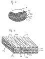
- FIGS. 2 and 3 show two exemplary embodiments of the laminated wood panel 1 of Fig. 1.
- a veneer plywood panel 1a is shown.
- These Veneered plywood panel 1 a is of a variety of flat superimposed and veneer layers glued together over the entire surface.
- An upper one Cover veneer layer 21a has one in a first direction, for example in a rectangular plate 1 a in the plate longitudinal direction, aligned Graining.
- a similar fiber course has a directly below it lying, second veneer layer 23a. This is followed by further veneer layers, z. B.
- two veneer layers 25a with fibers in a second, transverse to are aligned first direction extending direction, two more Veneer layers 27a, in turn, along the first direction having aligned fibers, as well as the layer composite if desired, symmetrically complementary veneer layers.
- the first and the second fiber direction is preferably approximately perpendicular to one another.
- the total number of veneer layers can be different, with the number of veneer layers extending along the first direction Fibers readily from the number of veneer layers with longitudinal to second direction extending fibers can differ. In this way can depend on the expected loads of Veneer plywood panel 1 a a plate different fracture strength 1 a in different directions be brought about.
- the veneer layers are with a thickness of 2 to 5mm, preferably about 3mm, made of spruce or pine wood by round peeling of the trunks produced.
- a variety of longitudinal cracks which also after Connection of the veneers to the veneer laminated wood board 1a throughout stay. After Formplatte1a this is in the boiler pressure with a wood preservative impregnated.
- the wood preservative enters the End faces of the individual veneer layers in the longitudinal cracks and wanders into the interior of veneer plywood panel 1a. That way all veneer layers impregnated over their entire length, so that a completely effetimstorygn Of veneer plywood panel 1 a of high weather resistance and life preserves.
- Fig. 3 shows a glulam board 1b, in turn, a variety of in pairs adjacent wood layer flat sides 29b over the entire surface with each other bonded wood layers 31b includes.
- the wood layers 31b include in each case several wooden boards 33b, the wood fibers within a Wood layer 31b approximately parallel to each other. All in pairs adjacent wood layers 31b are approximately perpendicular to each other running fiber directions.
- the pairwise adjacent and with each other bonded wood layer flat sides 29b are each having a plurality in Fiber direction of the respective layer extending, each other in the provided substantially parallel longitudinal grooves 35b, so that the adjacent Wood layer flat sides 29b of pairs adjacent Wood layers 31b have crossing longitudinal grooves 35b.
- the inner layers of wood formed by the wood layers 31b Stacks are on both of their wood layer flat sides 29b with longitudinal grooves 35b provided.
- the outer layers of wood 31b so the Top layers of the stack, longitudinal grooves 35b only on their inward towards the stack facing wood layer flat side 29b.
- the longitudinal grooves 35b in the wood layer flat sides 29b of the individual Wood layers 31b have a mutual distance of about 15 to 120mm, preferably from about 20-30mm, on. Their width is a few Millimeter.
- the longitudinal grooves 35b preferably have a groove depth, the is greater than half the thickness of a wood layer 31b. This is especially true for such wood layers 31 b, only on one of their wood layer flat sides are provided with longitudinal grooves 35b, and also for such wood layers 31b, provided on both of their wood layer flat sides with longitudinal grooves 35b are, but which are offset from one another.
- the limit for the Groove depth of the longitudinal grooves 35b is about 0.8 times the thickness of a Wood layer 31b lie, otherwise an impairment of the mechanical stability of the plate 1b is to be feared.
- the mutual Distance of longitudinal grooves 35b need not be the same for all longitudinal grooves 35b, although a uniform distribution of the longitudinal grooves 35b recommends. If individual wood layers, which is not shown in Fig. 3, on have their two wood layer flat sides 29b longitudinal grooves 35b, the Run in pairs in the same cross-sectional plane, the groove depth of the Longitudinal grooves 35b clearly less than half the thickness of a Be wood layer 31b.
- the wood fiber direction changes in the plywood board shown in FIG 1 b of wood layer to wood layer. It is understood, however, that a Stackwise of the wood layers 31b is conceivable, in each case two or more consecutive layers of wood 31b uniformly running wood fibers have. In any case, there is an all-round traction-resistant, stiffened Laminated wood board 1b, in the faulting substantially not are afraid.
- the advantage that they are small bumps or twisting of the boards 33b during gluing and pressing can compensate.
- the compression of the boards provided with adhesive 33b is preferably carried out in the vacuum bonding process in which the Wood layers 31b on a support, for example in a tub, be stacked, and then this carrier with an airtight Foil coat is covered.
- the thus formed airtight sealable Enveloping will be at least part of the setting time of the adhesive evacuated, so that the boards 33b under one of the atmospheric Air pressure corresponding pressing pressure are pressed. By contribution the wrapping with the wood stack contained in it Pressure vessel can also be achieved higher pressures.
- FIGS 4 and 5 show one using prefabricated wall panels 37c built noise protection wall.
- the wall panel 37c is used as a finished element delivered to the site and includes an anchored in the ground 5c Plywood panel 1 c, which is arranged with her above the ground Wall surface area 3c a first, substantially closed area forms over the entire wall panel 37c extending material layer 39c.
- a second, flat side spaced from the first material layer 39c Material layer 41c is formed by sound absorbing mats 43c.
- the Mats 43c are spaced apart by spacers 45c Plywood plate 1c held, these spacers 45c of an the plywood plate 1 c attached stiffening ribs 1 9c be formed can.
- the spacers 45c extend into the Slit recording 11 c, in which the plywood plate 1 c with her Anchoring area 7c is inserted.
- the spacers 45c may but also of a plurality of individual spacer blocks, e.g. cuttings be made of wood, which are attached to the plywood plate 1c.
- the Round wooden piles 47c cover the sound absorbing mats 43c. she sound-breaking, thus representing a first stage of sound insulation.
- the roundwood piles 47c are on horizontal bar pieces 49c, for example, by nails, attached to the noise source facing Side of the laminated wood panel 1c are attached.
- the strips 49c each extend between the stiffening ribs 19c, but can also pass over the entire plywood panel 1c when the Spacer elements 45c are formed by individual spacer blocks.
- the two material layers 39c and 41c define a plurality between them Hall spaces 51c, in which, if desired, additional sound-absorbing Components can be arranged.
- a cover 53c for example made of wood, covers the wall panel 37c on its entire length.
- cover strips 55c can be a closed transition between successive wall panels 37c the noise barrier be achieved, the cover strips 55c also for Fixing the wall panels 37c can serve each other.
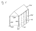
- Fig. 6 finally shows schematically a building 57d.
- the building 57d comprises a frame 59d, the vertically upstanding pendulum supports 61d includes.
- the pendulum supports 61d are each articulated in static terms attached to a concrete base 63d.
- To stiffen the frame 59d at least one stiffening wall plate 65d provided in the shown example case for a side wall of the building 57d more Wall elements in the form of anchored directly in the ground Plywood panels 1d covered.
- the wall plate 65d is on the frame 59d attached.
- the shown construction of the building 57d is suitable both for residential buildings as well as for agricultural buildings or for Hall buildings, for example, rotting halls.
Landscapes
- Engineering & Computer Science (AREA)
- Architecture (AREA)
- Civil Engineering (AREA)
- Structural Engineering (AREA)
- Life Sciences & Earth Sciences (AREA)
- Sustainable Development (AREA)
- Building Environments (AREA)
- Floor Finish (AREA)
- Finishing Walls (AREA)
- Veneer Processing And Manufacture Of Plywood (AREA)
- Load-Bearing And Curtain Walls (AREA)
- Joining Of Building Structures In Genera (AREA)
Description
- wenigstens zwei flachseitig benachbarte Materiallagen, die zwischen sich ein Volumen im wesentlichen geschlossenflächig begrenzen und von denen wenigstens eine aus schalldämmendem Material besteht,
- eine Halträumanordnung innerhalb des von den beiden Materiallagen begrenzten Volumens und
- Verankerungsmittel zur Verankerung des Wandfelds am Boden.
- Fig. 1
- eine in einen verfüllten Bodenschlitz eingestellte Schichtholzplatte,
- Fig. 2
- einen vergrößerten Ausschnitt eines ersten Ausführungsbeispiels der Schichtholzplatte der Fig. 1,
- Fig. 3
- einen vergrößerten Ausschnitt eines zweiten Ausführungsbeispiels der Schichtholzplatte der Fig. 1,
- Fig. 4
- einen Horizontalschnitt durch ein Wandfeld einer Lärmschutzwand, gesehen entlang einer Linie IV-IV in Fig. 5,
- Fig. 5
- einen Vertikalschnitt durch das Wandfeld der Fig. 4, gesehen entlang einer Linie V-V in Fig. 4, und
- Fig. 6
- schematisch ein Gebäude mit mehreren im Boden eingespannten Schichtholzplatten.
Claims (23)
- Verfahren zur Errichtung einer Wand einer Baukonstruktion, bei dem mindestens ein tafelförmiges Wandelement (1) aus Holz vertikal mit einem über dem Boden aufragenden Wandflächenbereich (3) aufgestellt und am Boden (5) durch Verankerungsmittel (7, 9, 17, 13) verankert wird, die in den Boden (5) eingelassen werden und auf den Wandflächenbereich (3) quer zur Wandebene des Wandelements (1) einwirkende Kräfte aufnehmen und in den Boden (5) ableiten,
wobei zur Bildung des Wandelements (1) eine mit einem Holzschutzmittel im wesentlichen durchimprägnierte Schichtholzplatte (1) aufgestellt wird, deren in der Endmontagestellung über dem Boden (5) aufragender Teil den Wandflächenbereich (3) bildet und zu deren Verankerung ein flächiger Verankerungsbereich (7) als integraler Teil der Schichtholzplatte (1) in eine im Boden (5) vorbereitete Schlitzaufnahme (11) eingesetzt wird, die anschließend mit einem Füllmaterial (9) verfüllt wird, wobei die Schichtholzplatte (1) die folgenden Merkmale aufweist:dadurch gekennzeichnet, daß die Schichtholzplatte (1) in ihrem Verankerungsbereich (7) mit mehreren quer von der Schichtholzplatte (1) abstehenden Verankerungsorganen (17) versehen wird, welche bei der Verfüllung der Schlitzaufnahme (11) von dem Füllmaterial (9) umschlossen werden.a) sie umfaßt mindestens zwei, insbesondere mehrere, flach aufeinanderliegende Holzschichten (21a, 23a, 25a, 27a;31b),b) die Hoizschichien (21a, 23a, 25a, 27a; 31b) sind an paarweise benachbarten Holzschicht-Flachseiten (29b) flächig, insbesondere vollflächig, miteinander verklebt undc) zumindest ein Teil der paarweise benachbarten Holzschichten (21a, 23a, 25a, 27a; 31b) weist quer, insbesondere etwa senkrecht, zueinander zulaufende Faserrichtungen ihrer Holzfasern auf, - Verfahren nach Anspruch 1, dadurch gekennzeichnet, daß eine Schichtholzplatte (1a; 1b) aufgestellt wird, die zumindest in einem Teil der Holzschichten (21a, 23a, 25a, 27a; 31b) im wesentlichen in Faserrichtung der jeweiligen Schicht verlaufende Längskanäle (35b) aufweist.
- Verfahren nach Anspruch 2, dadurch gekennzeichnet, daß eine als Platte druckimprägnierte Schichtholzplatte (1a; 1b) aufgestellt wird.
- Verfahren nach einem der Ansprüche 1 bis 3, dadurch gekennzeichnet, daß eine als Furnierschichtholzplatte (1a) ausgebildete Schichtholzplatte (1a) aufgestellt wird, deren rundgeschälte Fumierschichten (21a, 23a, 25a, 27a) eine zu Längsrissen führende Dicke haben.
- Verfahren nach Anspruch 4, dadurch gekennzeichnet, daß eine Furnierschichtholzplatte (1a) aufgestellt wird, deren Furnierschichten (21a, 23a, 25a, 27a) eine Dicke zwischen 2 und 5 mm, vorzugsweise von etwa 3 mm haben.
- Verfahren nach einem der Ansprüche 1 bis 3, dadurch gekennzeichnet, daß eine Schichtholzplatte (1b) aufgestellt wird, bei der zumindest ein Teil der Holzschichten (31b) jeweils auf mindestens einer Holzschicht-Flachseite (29b) mit mehreren zueinander annähernd parallelen und im wesentlichen in Faserrichtung der jeweiligen Schicht verlaufenden Längsnuten (35b) versehen ist.
- Verfahren nach Anspruch 6, dadurch gekennzeichnet, daß eine Schichtholzplatte (1b) aufgestellt wird, bei der zumindest ein Teil der paarweise benachbarten Holzschicht-Flachseiten (29b) jeweils mit Längsnuten (35b) versehen ist, derart, daß zumindest bei einem Teil der mit quer zueinander verlaufenden Faserrichtungen paarweise benachbarten Holzschichten (31 b) die Längsnuten (35b) der benachbarten Holzschidlt-Flachseiten (29b) sich kreuzen.
- Verfahren nach einem der Ansprüche 6 oder 7, dadurch gekennzeichnet, daß eine Schichtholzplatte (1b) aufgestellt wird, bei der wenigstens eine der Holzschichten (31b) lediglich auf einer ihrer Holzschicht-Flachseiten (29b) mit Längsnuten (35b) versehen ist und diese Längsnuten (35b) eine Tiefe von mindestens der Hälfte der Dicke dieser Holzschicht (31b) aufweisen, insbesondere eine Tiefe im Bereich des 0,5 bis 0,8-fachen der Dicke.
- Verfahren nach Anspruch 8, dadurch gekennzeichnet, daß eine Schichtholzplatte (1b) aufgestellt wird, bei der die auf den beiden Holzschicht-Flachseiten (29b)wenigstens einer Holzschicht (31b) vorgesehenen und auf Lücke versetzt angeordneten Längsnuten (35b) eine Tiefe von mindestens der Hälfte der Dicke dieser Holzschicht (31b) aufweisen, insbesondere eine Tiefe im Bereich des 0,5 bis 0,8-fachen der Dicke.
- Verfahren nach einem der Ansprüche 6 bis 9, dadurch gekennzeichnet, daß eine Schichtholzplatte (1b) aufgestellt wird, bei der die auf einer Holzschicht-Flachseite (29b) vorgesehenen Längsnuten (35b) einen gegenseitigen Abstand von etwa 15 bis 120 mm, insbesondere 20 bis 30 mm, aufweisen.
- Verfahren nach einem der Ansprüche 1 bis 3 und 6 bis 10, dadurch gekennzeichnet, daß eine Schichtholzplatte (1b) aufgestellt wird, bei der zumindest ein Teil der Holzschichten (31b) jeweils von einer Mehrzahl mit etwa parallelen Faserrichtungen eng beieinander liegender Holzelemente (33b), insbesondere schmalseitig nebeneinander liegender Holzbretter (33b), gebildet ist.
- Verfahren nach einem der Ansprüche 1 bis 11, dadurch gekennzeichnet, daß die Schlitzaufnahme (11) nach dem Einsetzen der Schichtholzplatte (1) zumindest teilweise mit Erd- oder Steinmaterial verfüllt und dieses sodann verdichtet wird.
- Verfahren nach einem der Ansprüche 1 bis 12, dadurch gekennzeichnet, daß die Schlitzaufnahme (11) nach dem Einsetzen der Schichtholzplatte (1) zumindest teilweise mit einem aushärtbaren Füllmaterial, insbesondere Beton, verfüllt wird.
- Verfahren nach einem der Ansprüche 1 bis 13, dadurch gekennzeichnet, daß die Schichtholzplatte (1) mit ihrem Verankerungsbereich (7) auf einem Teil ihrer vertikalen Höhe in die Schlitzaufnahme (11) eingesetzt wird, der mindestens einem Fünftel, insbesondere mindestens einem Viertel, beispielsweise etwa einem Drittel, der vertikalen Höhe des Wandflächenbereichs (3) entspricht.
- Verfahren nach einem der Ansprüche 1 bis 14, dadurch gekennzeichnet, daß eine auf mindestens einer ihrer Flachseiten mit mehreren zueinander etwa parallelen Aussteifungsrippen (19), insbesondere aus Holz, versehene Schichtholzplatte (1) unter annähernd vertikaler Ausrichtung der Aussteifungsrippen (19) so in die Schlitzaufnahme (11) eingesetzt wird, daß die Aussteifungsrippen (19) auf einem Teil ihrer Länge in die Schlitzaufnahme (11) hineinreichen und auf dem Restteil ihrer Länge aus der Schlitzaufnahme (11) herausragen.
- Baukonstruktion mit einer aus wenigstens einem vertikal aukustellenden tafelförmigen Wandelement (1) aus Holz gebildeten Wand, mit einem in der Endmontagestellung des Wandelements (1) über dem Boden (5) aufragenden Wandflächenbereich (3) und mit in den Boden (5) einzulassenden Verankerungsmitteln (7, 9, 17, 13) zur Verankerung des Wandelements (1) am Boden (5), wobei die Verankerungsmittel (7, 9, 17, 13) dazu ausgebildet sind, in der Endmontagestellung des Wandelements (1) quer zu dessen Wandebene auf den Wandflächenbereich (3) einwirkende Kräfte aufzunehmen und in den Boden (5) abzuleiten, wobei das Wandelement (1) als mit einem Holzschutzmittel durchimprägnierte Schichtholzplatte (1) ausgebildet ist, deren in der Endmontagestellung über dem Boden (5) aufragender Teil den Wandflächenbereich (3) bildet, wobei die Verankerungsmittel (7, 9, 17, 13) einen in eine Schlitzaufnahme (11) im Boden (5) einzusetzenden flächigen Verankerungsbereich (7) als integralen Teil der Schichtholzplatte (1) sowie eine Füllung (9) für die Schlitzaufnahme (11) umfassen, und wobei die Schichtholzplatte (1) die folgenden Maßnahmen aufweist:a) sie umfaßt mindestens zwei, insbesondere mehrere, flach aufeinanderliegende Holzschichten (21 a, 23a, 25a, 27a; 31 b),b) die Holzschichten (21a, 23a, 25a, 27a; 31b) sind an paarweise benachbarten Holzschicht-Flachseiten (29b) flächig, insbesondere vollflächig, miteinander verklebt undc) zumindest ein Teil der paarweise benachbarten Holzschichten (21a, 23a, 25a, 27a; 31b) weist quer, insbesondere etwa senkrecht, zueinander verlaufende Faserrichtungen ihrer Hotzfasem auf, dadurch gekennzeichnet, daß die Schichtholzplatte (1) in ihrem Verankerungsbereich (7) mehrere quer von der Schichtholzplatte (1) abstehende, in der Schlitzaufnahme (11) von dem Füllmaterial (9) umschlossene Verankerungsorgane (17) aufweist.
- Baukonstruktion nach Anspruch 16, dadurch gekennzeichnet, daß zumindest ein Teil der Verankerungsorgane (17) von Verankerungsstäben oder -stiften (17) gebildet ist, welche in Querbohrungen in der Schichtholzplatte (1) eingesetzt sind.
- Baukonstruktion nach Anspruch 16 oder 17, dadurch gekennzeichnet, daß die Verankerungsmittel (7, 9, 17, 13) auch zur Aufnahme und Ableitung von in der Endmontagestellung längs des Wandelements (1), insbesondere etwa parallel zum Boden (5), auf den Wandflächenbereich (3) einwirkenden Kräften ausgebildet sind.
- Baukonstruktion nach einem der Ansprüche 16 bis 18, dadurch gekennzeichnet, daß die Verankerungsmittel (7, 9, 17, 13) zur Aufnahme und Ableitung wenigstens des überwiegenden Teils der in der Endmontagestellung auf das Wandelement (1) einwirkenden Einspannkräfte ausgebildet sind.
- Baukonstruktion nach einem der Ansprüche 16 bis 19, dadurch gekennzeichnet, daß die Verankerungsmittel (7, 9, 17, 13) eine Ortbeton-Füllung (9) für die Schlitzaufnahme (11) umfassen.
- Baukonstruktion nach einem der Ansprüche 16 bis 19, dadurch gekennzeichnet, daß die Verankerungsmittel (7, 9, 17, 13) eine Ortfüllung (9) aus verdichtetem Erd- oder Steinmaterial für die Schlitzaufnahme (11) umfassen.
- Baukonstruktion nach einem der Ansprüche 16 bis 21, dadurch gekennzeichnet, daß die Verankerungsmittel (7,9, 17, 13) eine druckfeste Auflagerschicht (13) für die Schichtholzplatte (1) am Grund der Schlitzaufnahme (11) umfassen.
- Baukonstruktion nach einem der Ansprüche 16 bis 22, dadurch gekennzeichnet, daß die Verankerungsmittel (7, 9, 17, 13) eine entlang der Schlitzaufnahme (11) mindestens einseitig über den VerankerungsBereich (7) der Schichtholzplatte (1) hinausreichende Füllung (9) für die Schlitzaufnahme (11) umfassen.
Applications Claiming Priority (2)
| Application Number | Priority Date | Filing Date | Title |
|---|---|---|---|
| DE19733880 | 1997-08-05 | ||
| DE19733880A DE19733880A1 (de) | 1997-08-05 | 1997-08-05 | Verfahren zur Errichtung einer Wand einer Baukonstruktion Stichwort: Verankerung einer Schichtholzplatte im Boden |
Publications (3)
| Publication Number | Publication Date |
|---|---|
| EP0896096A2 EP0896096A2 (de) | 1999-02-10 |
| EP0896096A3 EP0896096A3 (de) | 2002-06-12 |
| EP0896096B1 true EP0896096B1 (de) | 2005-03-02 |
Family
ID=7838071
Family Applications (1)
| Application Number | Title | Priority Date | Filing Date |
|---|---|---|---|
| EP98111017A Expired - Lifetime EP0896096B1 (de) | 1997-08-05 | 1998-06-16 | Verfahren zur Verankerung einer Schichtholzplatte im Boden, und damit hergestellte Baukonstruktion |
Country Status (3)
| Country | Link |
|---|---|
| EP (1) | EP0896096B1 (de) |
| AT (1) | ATE290128T1 (de) |
| DE (2) | DE19733880A1 (de) |
Cited By (1)
| Publication number | Priority date | Publication date | Assignee | Title |
|---|---|---|---|---|
| WO2011087397A1 (ru) * | 2010-01-15 | 2011-07-21 | Shatalov Vladimir Mikhailovich | Панель |
Families Citing this family (1)
| Publication number | Priority date | Publication date | Assignee | Title |
|---|---|---|---|---|
| DK199900318U4 (da) * | 1999-09-03 | 2000-01-28 | Peter B Jensen | Støjskærme af træ |
Family Cites Families (15)
| Publication number | Priority date | Publication date | Assignee | Title |
|---|---|---|---|---|
| DE553854C (de) * | 1930-10-18 | 1932-07-01 | Schmidt Karl | Kernbrett fuer Sperrplatten, dessen Faserzusammenhang teilweise zerstoert ist |
| CH376139A (it) * | 1960-01-07 | 1964-03-31 | Samac Societa Per Azioni | Dispositivo delineatore e segnalimite stradale |
| US4175639A (en) * | 1976-11-16 | 1979-11-27 | Lockheed Corporation | Noise barrier |
| DE2743980C3 (de) * | 1977-09-30 | 1981-06-25 | Grage, Joachim, Dipl.-Ing., 6900 Heidelberg | Schallschutzwand aus lotrecht nebeneinander angeordneten und miteinander verbundenen Einzelelementen aus Kunststoff |
| US4402384A (en) * | 1981-11-04 | 1983-09-06 | Hoover Universal, Inc. | Sound barrier system |
| DE3244618C1 (de) * | 1982-12-02 | 1984-06-07 | Dyckerhoff & Widmann AG, 8000 München | Schallschutzwand, insbesondere für Verkehrswege |
| DE8337416U1 (de) * | 1983-12-28 | 1984-03-29 | Werth-Holz GmbH & Co KG, 5950 Finnentrop | Schallschutzwand |
| CA1210340A (en) * | 1984-02-07 | 1986-08-26 | Ernst U. Boehlau | Noise barrier |
| CH678872A5 (de) * | 1989-03-15 | 1991-11-15 | Hermann Claus | |
| DE4126657C1 (en) * | 1991-08-13 | 1992-08-27 | Karl-Heinz 8050 Freising De Freitag | Vegetative sound barrier with longitudinal walls - has each wall of longitudinal elements with vertical, tightly packed willow braches |
| DE9207654U1 (de) * | 1992-03-12 | 1992-10-01 | Holzbau Amann GmbH, 7891 Weilheim | Holzbautafel |
| DE4242824A1 (de) * | 1992-12-17 | 1994-06-23 | Moser Karl Dipl Ing Fh | Wandfeld, insbesondere für eine Lärmschutzwand |
| DE4416201A1 (de) | 1994-05-06 | 1995-11-09 | Karl Moser | Schalldämmendes Wandfeld |
| DE9408382U1 (de) * | 1994-05-20 | 1994-08-04 | Egle, Wilhelm, 79733 Görwihl | Holzbauelement mit Holzlagen |
| DE29622260U1 (de) * | 1996-12-21 | 1997-02-06 | Lignotrend Holzblocktafel Systeme GmbH, 79809 Weilheim | Holzbautafel für Decken, Wände und Dächer |
-
1997
- 1997-08-05 DE DE19733880A patent/DE19733880A1/de not_active Withdrawn
-
1998
- 1998-06-16 DE DE59812607T patent/DE59812607D1/de not_active Expired - Fee Related
- 1998-06-16 AT AT98111017T patent/ATE290128T1/de not_active IP Right Cessation
- 1998-06-16 EP EP98111017A patent/EP0896096B1/de not_active Expired - Lifetime
Cited By (1)
| Publication number | Priority date | Publication date | Assignee | Title |
|---|---|---|---|---|
| WO2011087397A1 (ru) * | 2010-01-15 | 2011-07-21 | Shatalov Vladimir Mikhailovich | Панель |
Also Published As
| Publication number | Publication date |
|---|---|
| DE59812607D1 (de) | 2005-04-07 |
| EP0896096A3 (de) | 2002-06-12 |
| ATE290128T1 (de) | 2005-03-15 |
| DE19733880A1 (de) | 1999-02-11 |
| EP0896096A2 (de) | 1999-02-10 |
Similar Documents
| Publication | Publication Date | Title |
|---|---|---|
| EP1097032B1 (de) | Vorgefertigtes schichtholzelement | |
| DE1807716A1 (de) | Vorgefertigtes,transportables Raumelement zur Herstellung von Bauwerken | |
| EP1511906B1 (de) | Holzbauelement und bausatz zum aufbau von gebäudewänden mit holzbauelementen | |
| EP2060694B1 (de) | Gebäudewandelement | |
| EP0952271A2 (de) | Holz-Beton-Verbundelement | |
| DE19828607A1 (de) | Verfahren zum Verstärken von Stahl- und Spannbetonbauteilen | |
| DE60007842T2 (de) | Platte, zusammenbau solcher platten und verwendung zum aufnehmen schwerer lasten | |
| EP0896096B1 (de) | Verfahren zur Verankerung einer Schichtholzplatte im Boden, und damit hergestellte Baukonstruktion | |
| DE69510045T2 (de) | Lärmschutzwand | |
| DE102008009057A1 (de) | Holzmastegründung | |
| EP2256262B1 (de) | Holzgebäudemodul, seine Verwendung, und Verfahren zu seiner Herstellung | |
| DE29824534U1 (de) | Holz-Beton-Verbundelement | |
| DE102020206226A1 (de) | Trägerelement und Verfahren zur Herstellung einer freikragenden Balkonanlage sowie Verwendung eines Trägerelements zur Herstellung einer freikragenden Balkonanlage | |
| DE60121182T2 (de) | Selbsttragendes baulelement aus holz | |
| DE202008014889U1 (de) | Gebäudewandelement | |
| AT520607B1 (de) | Fundament für einen Turm für eine Windenergieanlage | |
| DE19739402C2 (de) | Gebäudeecke für ein Haus in Holzbauweise | |
| CH697249B1 (de) | Holzbauelement. | |
| EP4514577A1 (de) | Holzbauelemente für gebäudedecken | |
| DE4242824A1 (de) | Wandfeld, insbesondere für eine Lärmschutzwand | |
| EP1318245B1 (de) | Verbundelement | |
| AT410566B (de) | Schalungsanordnung | |
| DE4234500A1 (de) | Holzbau, Holzbohle hierfür, sowie Verfahren zur Herstellung | |
| DE9003145U1 (de) | Schallschutzwand | |
| DE102009017185A1 (de) | Variable Gebäudekonstruktion für Holzhäuser |
Legal Events
| Date | Code | Title | Description |
|---|---|---|---|
| PUAI | Public reference made under article 153(3) epc to a published international application that has entered the european phase |
Free format text: ORIGINAL CODE: 0009012 |
|
| AK | Designated contracting states |
Kind code of ref document: A2 Designated state(s): AT BE CH CY DE DK ES FI FR GB GR IE IT LI LU MC NL PT SE |
|
| AX | Request for extension of the european patent |
Free format text: AL;LT;LV;MK;RO;SI |
|
| PUAL | Search report despatched |
Free format text: ORIGINAL CODE: 0009013 |
|
| AK | Designated contracting states |
Kind code of ref document: A3 Designated state(s): AT BE CH CY DE DK ES FI FR GB GR IE IT LI LU MC NL PT SE |
|
| AX | Request for extension of the european patent |
Free format text: AL;LT;LV;MK;RO;SI |
|
| 17P | Request for examination filed |
Effective date: 20021016 |
|
| AKX | Designation fees paid |
Designated state(s): AT CH DE FI FR LI SE |
|
| 17Q | First examination report despatched |
Effective date: 20031105 |
|
| GRAP | Despatch of communication of intention to grant a patent |
Free format text: ORIGINAL CODE: EPIDOSNIGR1 |
|
| RTI1 | Title (correction) |
Free format text: METHOD FOR ANCHORING A LAMINATED WOODEN PANEL IN THE SOIL, AND CONSTRUCTION THUS FORMED |
|
| GRAS | Grant fee paid |
Free format text: ORIGINAL CODE: EPIDOSNIGR3 |
|
| GRAA | (expected) grant |
Free format text: ORIGINAL CODE: 0009210 |
|
| AK | Designated contracting states |
Kind code of ref document: B1 Designated state(s): AT CH DE FI FR LI SE |
|
| REG | Reference to a national code |
Ref country code: CH Ref legal event code: NV Representative=s name: A. BRAUN, BRAUN, HERITIER, ESCHMANN AG PATENTANWAE Ref country code: CH Ref legal event code: EP |
|
| REG | Reference to a national code |
Ref country code: IE Ref legal event code: FG4D Free format text: GERMAN |
|
| REF | Corresponds to: |
Ref document number: 59812607 Country of ref document: DE Date of ref document: 20050407 Kind code of ref document: P |
|
| REG | Reference to a national code |
Ref country code: SE Ref legal event code: TRGR |
|
| PGFP | Annual fee paid to national office [announced via postgrant information from national office to epo] |
Ref country code: FR Payment date: 20050627 Year of fee payment: 8 Ref country code: FI Payment date: 20050627 Year of fee payment: 8 |
|
| PGFP | Annual fee paid to national office [announced via postgrant information from national office to epo] |
Ref country code: SE Payment date: 20050628 Year of fee payment: 8 |
|
| PGFP | Annual fee paid to national office [announced via postgrant information from national office to epo] |
Ref country code: AT Payment date: 20050629 Year of fee payment: 8 |
|
| PGFP | Annual fee paid to national office [announced via postgrant information from national office to epo] |
Ref country code: DE Payment date: 20050630 Year of fee payment: 8 |
|
| PGFP | Annual fee paid to national office [announced via postgrant information from national office to epo] |
Ref country code: CH Payment date: 20050714 Year of fee payment: 8 |
|
| PLBE | No opposition filed within time limit |
Free format text: ORIGINAL CODE: 0009261 |
|
| STAA | Information on the status of an ep patent application or granted ep patent |
Free format text: STATUS: NO OPPOSITION FILED WITHIN TIME LIMIT |
|
| ET | Fr: translation filed | ||
| 26N | No opposition filed |
Effective date: 20051205 |
|
| PG25 | Lapsed in a contracting state [announced via postgrant information from national office to epo] |
Ref country code: FI Free format text: LAPSE BECAUSE OF NON-PAYMENT OF DUE FEES Effective date: 20060616 Ref country code: AT Free format text: LAPSE BECAUSE OF NON-PAYMENT OF DUE FEES Effective date: 20060616 |
|
| PG25 | Lapsed in a contracting state [announced via postgrant information from national office to epo] |
Ref country code: SE Free format text: LAPSE BECAUSE OF NON-PAYMENT OF DUE FEES Effective date: 20060617 |
|
| PG25 | Lapsed in a contracting state [announced via postgrant information from national office to epo] |
Ref country code: LI Free format text: LAPSE BECAUSE OF NON-PAYMENT OF DUE FEES Effective date: 20060630 Ref country code: CH Free format text: LAPSE BECAUSE OF NON-PAYMENT OF DUE FEES Effective date: 20060630 |
|
| PG25 | Lapsed in a contracting state [announced via postgrant information from national office to epo] |
Ref country code: DE Free format text: LAPSE BECAUSE OF NON-PAYMENT OF DUE FEES Effective date: 20070103 |
|
| REG | Reference to a national code |
Ref country code: CH Ref legal event code: PL |
|
| EUG | Se: european patent has lapsed | ||
| REG | Reference to a national code |
Ref country code: FR Ref legal event code: ST Effective date: 20070228 |
|
| PG25 | Lapsed in a contracting state [announced via postgrant information from national office to epo] |
Ref country code: FR Free format text: LAPSE BECAUSE OF NON-PAYMENT OF DUE FEES Effective date: 20060630 |