EP0897047B1 - Verbindungselement für ein Hohlteil mit einem weiteren Teil im Tür- und Fensterbau - Google Patents
Verbindungselement für ein Hohlteil mit einem weiteren Teil im Tür- und Fensterbau Download PDFInfo
- Publication number
- EP0897047B1 EP0897047B1 EP98114395A EP98114395A EP0897047B1 EP 0897047 B1 EP0897047 B1 EP 0897047B1 EP 98114395 A EP98114395 A EP 98114395A EP 98114395 A EP98114395 A EP 98114395A EP 0897047 B1 EP0897047 B1 EP 0897047B1
- Authority
- EP
- European Patent Office
- Prior art keywords
- holding element
- holding
- hollow part
- bracing
- axis
- Prior art date
- Legal status (The legal status is an assumption and is not a legal conclusion. Google has not performed a legal analysis and makes no representation as to the accuracy of the status listed.)
- Expired - Lifetime
Links
- 238000010276 construction Methods 0.000 title claims description 3
- 238000003780 insertion Methods 0.000 description 4
- 230000037431 insertion Effects 0.000 description 4
- 230000003993 interaction Effects 0.000 description 2
- 238000004519 manufacturing process Methods 0.000 description 2
- 239000002184 metal Substances 0.000 description 2
Images
Classifications
-
- F—MECHANICAL ENGINEERING; LIGHTING; HEATING; WEAPONS; BLASTING
- F16—ENGINEERING ELEMENTS AND UNITS; GENERAL MEASURES FOR PRODUCING AND MAINTAINING EFFECTIVE FUNCTIONING OF MACHINES OR INSTALLATIONS; THERMAL INSULATION IN GENERAL
- F16B—DEVICES FOR FASTENING OR SECURING CONSTRUCTIONAL ELEMENTS OR MACHINE PARTS TOGETHER, e.g. NAILS, BOLTS, CIRCLIPS, CLAMPS, CLIPS OR WEDGES; JOINTS OR JOINTING
- F16B7/00—Connections of rods or tubes, e.g. of non-circular section, mutually, including resilient connections
- F16B7/04—Clamping or clipping connections
- F16B7/044—Clamping or clipping connections for rods or tubes being in angled relationship
- F16B7/0446—Clamping or clipping connections for rods or tubes being in angled relationship for tubes using the innerside thereof
-
- E—FIXED CONSTRUCTIONS
- E06—DOORS, WINDOWS, SHUTTERS, OR ROLLER BLINDS IN GENERAL; LADDERS
- E06B—FIXED OR MOVABLE CLOSURES FOR OPENINGS IN BUILDINGS, VEHICLES, FENCES OR LIKE ENCLOSURES IN GENERAL, e.g. DOORS, WINDOWS, BLINDS, GATES
- E06B3/00—Window sashes, door leaves, or like elements for closing wall or like openings; Layout of fixed or moving closures, e.g. windows in wall or like openings; Features of rigidly-mounted outer frames relating to the mounting of wing frames
- E06B3/96—Corner joints or edge joints for windows, doors, or the like frames or wings
- E06B3/964—Corner joints or edge joints for windows, doors, or the like frames or wings using separate connection pieces, e.g. T-connection pieces
- E06B3/968—Corner joints or edge joints for windows, doors, or the like frames or wings using separate connection pieces, e.g. T-connection pieces characterised by the way the connecting pieces are fixed in or on the frame members
- E06B3/972—Corner joints or edge joints for windows, doors, or the like frames or wings using separate connection pieces, e.g. T-connection pieces characterised by the way the connecting pieces are fixed in or on the frame members by increasing the cross-section of the connecting pieces, e.g. by expanding the connecting pieces with wedges
- E06B3/9725—Mitre joints
-
- F—MECHANICAL ENGINEERING; LIGHTING; HEATING; WEAPONS; BLASTING
- F16—ENGINEERING ELEMENTS AND UNITS; GENERAL MEASURES FOR PRODUCING AND MAINTAINING EFFECTIVE FUNCTIONING OF MACHINES OR INSTALLATIONS; THERMAL INSULATION IN GENERAL
- F16B—DEVICES FOR FASTENING OR SECURING CONSTRUCTIONAL ELEMENTS OR MACHINE PARTS TOGETHER, e.g. NAILS, BOLTS, CIRCLIPS, CLAMPS, CLIPS OR WEDGES; JOINTS OR JOINTING
- F16B2/00—Friction-grip releasable fastenings
- F16B2/005—Means to increase the friction-coefficient
-
- F—MECHANICAL ENGINEERING; LIGHTING; HEATING; WEAPONS; BLASTING
- F16—ENGINEERING ELEMENTS AND UNITS; GENERAL MEASURES FOR PRODUCING AND MAINTAINING EFFECTIVE FUNCTIONING OF MACHINES OR INSTALLATIONS; THERMAL INSULATION IN GENERAL
- F16B—DEVICES FOR FASTENING OR SECURING CONSTRUCTIONAL ELEMENTS OR MACHINE PARTS TOGETHER, e.g. NAILS, BOLTS, CIRCLIPS, CLAMPS, CLIPS OR WEDGES; JOINTS OR JOINTING
- F16B2/00—Friction-grip releasable fastenings
- F16B2/02—Clamps, i.e. with gripping action effected by positive means other than the inherent resistance to deformation of the material of the fastening
- F16B2/04—Clamps, i.e. with gripping action effected by positive means other than the inherent resistance to deformation of the material of the fastening internal, i.e. with spreading action
-
- F—MECHANICAL ENGINEERING; LIGHTING; HEATING; WEAPONS; BLASTING
- F16—ENGINEERING ELEMENTS AND UNITS; GENERAL MEASURES FOR PRODUCING AND MAINTAINING EFFECTIVE FUNCTIONING OF MACHINES OR INSTALLATIONS; THERMAL INSULATION IN GENERAL
- F16B—DEVICES FOR FASTENING OR SECURING CONSTRUCTIONAL ELEMENTS OR MACHINE PARTS TOGETHER, e.g. NAILS, BOLTS, CIRCLIPS, CLAMPS, CLIPS OR WEDGES; JOINTS OR JOINTING
- F16B21/00—Means for preventing relative axial movement of a pin, spigot, shaft or the like and a member surrounding it; Stud-and-socket releasable fastenings
- F16B21/02—Releasable fastening devices locking by rotation
Definitions
- the invention relates to a connecting element for a hollow part with a further part in the door and window construction according to the preamble of patent claim 1.
- a generic connector is known from FR-A-1 497 682.
- the invention has for its object to further develop a generic connection element so that a simple, fast and secure connection between the holding member and the hollow part is achieved.
- the expansion element has a running in the direction of the axis of the holding element mecanicukant Formula and the fixed connection can be formed by rotating the expansion element about the axis of the hollow part.
- the polygonal surface allows the insertion of a polygonal key to twist the spreader and the rotation of the spotting element about the axis of the hollow part allows easy access to the spreader at the open end of the hollow part.
- the connecting element thus has the advantage that by means of a polygonal key, the expansion element can be taken at the open end of the hollow part in order to rotate the expansion element.
- the expansion element has at least one arcuate surface which cooperates with a corresponding arcuate surface on the holding element.
- Concave surfaces on the retaining element and convex surfaces on the expansion element increase the space in which the expansion element is moved, and increase the effective areas between the expansion element and the retaining element.
- latching means are provided on the expansion element and / or on the retaining element.
- These locking means may be interlocking teeth.
- the locking means may also be formed by cooperating concave and convex surfaces. If a permanent connection is desired, a ramp and an undercut are proposed as locking means, which cooperate with a protruding element on the opposite part and thus allow easy tightening, but prevent turning back of the spreader.
- the expansion element has a through hole in the direction of the axis of the retaining element.
- a bore has the further advantage that in the through hole a rod can be performed, which is used for example for locking a door.
- the door locking bolt which runs vertically in the door leaf and connects the door leaf with the door frame and the floor sill, can pass through the expansion element.
- the door drive latch is guided in the expansion element.
- the outer shape of the retaining element is adapted to the inner shape of the hollow part. This makes it possible to use the space within the hollow part as completely as possible.
- the holding element is thereby guided in the hollow part and there are large surfaces for interaction between the holding element and the hollow part.
- the outer shape of the holding element has relatively small elevations, which form the connecting surface between the holding element and the hollow part.
- the height of the elevations may be matched to the maximum manufacturing tolerance between the holding element and the hollow part, so that when connecting the holding element in the hollow part always creates a connection surface between the holding element and the hollow part. If the holding element is too large or the hollow part is made too small, the holding element is bent at the locations of the elevations, the elevations are compressed or part of the elevations is ground during insertion of the holding element. This ensures a good management of the retaining element in the hollow part even with manufacturing tolerances.
- the expansion element and the retaining element are parts of a corner connector. Especially in the field of corner connectors in door and window sash such fasteners are sought because they are invisible attachable from the outside and allows a quick, easy, easily automatable connection of the hollow parts.
- the connecting element is also well suited to connect a plurality of nested hollow parts together. This is necessary, for example, in metal profiles used in extruded profiles.
- the holding element has a bore or a depression on the axis of the corresponding holding element of the corner connector. If in a holding element of the corner connector a rod, such as a door latch is performed, the bore in the corresponding holding element of the corner connector serves to pass the rod or the door latch by the corresponding holding element of the corner connector. Instead of a bore, only one depression can be provided, which indicates the position of the bore to be attached and facilitates the attachment of a bore, if a bore is required.
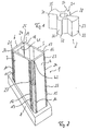
- FIGS. 1 and 2 show a holding element 1 and a spreading element 2 which, as shown in FIG. 3, can be put together to form a connecting element 3.
- the holding element shown in Figure 2 consists of a at an angle of 45 ° to the side walls 4, 5, 6, 7 arranged base 8.
- This base 8 serves to produce a right-angled elbow with a further holding element as in the known corner connectors.
- the side surfaces are arranged in the present case to each other so that they form a rectangle which fits into the hollow part 9 shown in Figure 5.
- outer surfaces of the sides 4, 5, 6, 7 of the holding element 1 are in the direction of the axis of the hollow part 9, which is a profile tube in the present case, provided as elevations cam 10 to 21, which upon insertion of the holding element 1 rest in the profile tube 9 on the profile tube 9. If that Profile tube 9 is not dimensionally stable, 9 parts of the cam 10 to 21 are deformed or abraded when inserting the retaining element 1 in the profile tube.
- the holding member 1 has a lower portion 22 in which side walls 4, 5, 6, 7 are connected at their corners, and an upper portion 23 in which between the edges of the side walls 4 to 7 each have a gap 24, 25, 26th , 27 is provided.
- the columns 24 to 27 are all the same length.
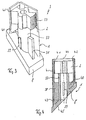
- a spreader 2 is used, which is shown in more detail in Figure 1.
- the expansion element 2 is a rotationally symmetrical body with a central secheckigen bore 28 and symmetrically arranged two larger wing portions 29, 30 and two smaller wing portions 31, 32. These wing portions have radially outer convex surfaces 33, 34, 35, 36, the radially as far are arranged outside, that the spreader 2 is still inserted into the holding element 1.
- FIG. 3 shows a spreader element 2 inserted into the retaining element 1, and in this spreader element 2 a serrated structure is drawn on a radially outer surface 33 of the spreader element 2, which, as described below, acts as a latching element.
- a prong structure may also be provided on the remaining surfaces 34, 35, 36 of the expansion element 2.
- the insight into the holding element 1 shown in Figure 2 shows that on the base 8 of the holding element 1, a cylindrical body 37 is provided, which is stabilized by support walls 38, 39, 40 and in the holding element. 1 used spreading element 2 carries. Falling out of the expansion element 2 from the support member 1 is prevented by protruding lugs 41, 42, which are arranged at the upper end of two opposite side walls 4, 6.
- a recess 43 is incorporated, which serves as a drill bit approach for an attachable at this point bore.
- the position of the recess 43 is selected so that an attached at this point at right angles to the side wall 4 bore the axis 44 of the support member 1 in the region of the bottom 45 of the base 8 intersects. If the base of another holding element is applied to the base 45 of the first holding element, so that a right angle between the Garelemeneten, a bore can be attached to the recess 43, which is aligned with the axis of the further holding element. This makes it possible to guide in the holding element a rod such as a drive rod, which emerges from the holding element 1 in the region of the recess 43.
- the holding element 1 has a base 8 which is arranged at an angle of 45 degrees to the axis 44 of the holding element 1.
- the holding element 1 can also be formed with a base surface arranged at right angles to a side surface 4, or two holding elements with oblique base surfaces can be arranged in mirror image relative to one another such that hollow parts lying on an axis 44 can be connected to one another.
- the expansion element is rotated about 20 degrees clockwise about the axis of the bore 28.
- the concave sides 33, 35 and 34, 36 of the wings 29, 30 and 31, 32 press against the inside of the side walls 4, 5, 6, 7, whereby the side walls are pressed to the outside against the inside of the hollow section 9.
- the expansion element 2 is rotated as long as the axis of the bore 28 until a sufficiently firm contact of the holding element 1 is produced on the hollow section 9.
- a sliding back of the expansion against the rotation performed is prevented by locking elements 46 on the side 33 of at least one wing of the expansion element 2, which cooperate with a protruding element 47 on the inside of a side wall 6.
- a locking toothing 46, 47 is provided as a latching device.
- concave recesses are provided on the inside of the walls 4, 5, 6, 7 of the holding element, which cooperate as a counterpart with the surfaces 33, 34, 35, 36 of the expansion element 3.
Landscapes
- Engineering & Computer Science (AREA)
- General Engineering & Computer Science (AREA)
- Mechanical Engineering (AREA)
- Civil Engineering (AREA)
- Structural Engineering (AREA)
- Mutual Connection Of Rods And Tubes (AREA)
- Joining Of Corner Units Of Frames Or Wings (AREA)
- Connection Of Plates (AREA)
Description
- Die Erfindung betrifft ein Verbindungselement für ein Hohlteil mit einem weiteren Teil im Tür- und Fensterbau gemäß dem Oberbegriff des Patentanspruchs 1.
- Ein gattungsgemäßes Verbindungselement ist aus der FR-A-1 497 682 bekannt.
- Der Erfindung liegt die Aufgabe zugrunde, ein gattungsgemäßes Verbindungselement so weiterzuentwickeln, daß eine einfache, schnelle und sichere Verbindung zwischen dem Halteelement und dem Hohlteil erzielt wird.
- Diese Aufgabe wird dadurch gelöst, daß das Spreizelement eine in Richtung der Achse des Halteelementes verlaufende Innenvielkantfläche aufweist und die feste Verbindung durch Drehen des Spreizelementes um die Achse des Hohlteils entstehen kann.
- Die Vielkantfläche erlaubt das Einsetzen eines Vielkantschlüssels, um das Spreizelement zu verdrehen und das Drehen des Speizelementes um die Achse des Hohlteils erlaubt einen einfachen Zugriff auf das Spreizelement am offenen Ende des Hohlteils. Das Verbindungselement hat somit den Vorteil, daß mittels eines Vielkantschlüssels das Spreizelement am offenen Ende des Hohlteils ergriffen werden kann, um das Spreizelement zu verdrehen.
- Vorteilhaft ist es, wenn das Spreizelement mindestens eine bogenförmige Fläche aufweist, die mit einer entsprechenden bogenförmigen Fläche am Halteelement zusammenwirkt. Konkave Flächen am Halteelement und konvexe Flächen am Spreizelement vergrößern den Raum, in dem das Spreizelement bewegt wird, und vergrößern die Wirkflächen zwischen Spreizelement und Halteelement.
- Eine bevorzugte Ausführungsform sieht vor, daß am Spreizelement und/oder am Halteelement Rastmittel vorgesehen sind. Diese Rastmittel können ineinandergreifende Zähne sein. Die Rastmittel können jedoch auch von miteinander zusammenwirkenden konkaven und konvexen Flächen gebildet werden. Wenn eine unlösbare Verbindung gewünscht wird, wird als Rastmittel eine Rampe und eine Hinterschneidung vorgeschlagen, die mit einem vorstehenden Element am gegenüberliegenden Teil zusammenwirken und somit ein leichtes Festdrehen ermöglichen, aber ein Zurückdrehen des Spreizelementes verhindern.
- Um das Gewicht des Spreizelements zu reduzieren, wird vorgeschlagen, daß das Spreizelement eine Durchbohrung in Richtung der Achse des Halteelements aufweist. Eine derartige Durchbohrung hat den weiteren Vorteil, daß in der Durchbohrung eine Stange geführt werden kann, die beispielsweise zur Verriegelung einer Tür verwendet wird. Insbesondere bei Stülptüren kann der Türtreibriegel, der senkrecht im Türflügel verläuft und den Türflügel mit dem Türrahmen und der Bodenschwelle verbindet, durch das Spreizelement hindurchlaufen. Vorzugsweise wird der Türtreibriegel im Spreizelement geführt.
- Vorteilhaft ist es, wenn die äußere Form des Halteelements der inneren Form des Hohlteil angepaßt ist. Dies erlaubt es, den Raum innerhalb des Hohlteils möglichst vollständig zu nutzen. Außerdem wird das Halteelement dadurch im Hohlteil geführt und es entstehen große Flächen zum Zusammenwirken zwischen Halteelement und Hohlteil.
- Insbesondere bei einem Zusammenwirken von Hohlteilen aus Metall und Halteelementen aus Kunststoff ist es vorteilhaft, wenn die äußere Form des Halteelements relativ kleine Erhebungen aufweist, die die Verbindungsfläche zwischen Halteelement und Hohlteil bilden. Die Höhe der Erhebungen kann auf die maximale Fertigungstoleranz zwischen Halteelement und Hohlteil abgestimmt sein, so daß beim Einführen des Halteelements in das Hohlteil immer eine Verbindungsfläche zwischen Halteelement und Hohlteil entsteht. Sofern das Halteelement zu groß oder das Hohlteil zu klein gefertigt ist, wird das Halteelement an den Stellen der Erhebungen verbogen, die Erhebungen werden zusammengedrückt oder ein Teil der Erhebungen wird beim Einführen des Halteelements abgeschliffen. Dies gewährleistet auch bei Fertigungstoleranzen eine gute Führung des Halteelements im Hohlteil.
- Eine bevorzugte Anwendung sieht vor, daß das Spreizelement und das Halteelement Teile eines Eckverbinders sind. Gerade im Bereich von Eckverbindern bei Tür- und Fensterflügeln sind derartige Verbindungselemente gesucht, da sie von außen unsichtbar anbringbar sind und eine schnelle, einfache, leicht automatisierbare Verbindung der Hohlteile erlaubt. Außerdem ist das Verbindungselement auch gut dazu geeignet, mehrere ineinandergesteckte Hohlteile miteinander zu verbinden. Dies ist beispielsweise bei in Stranggußprofilen eingesetzten Metallprofilen notwendig.
- Beim Einsatz des Verbindungselementes als Teil eines Eckverbinders ist es vorteilhaft, wenn das Halteelement eine Bohrung oder eine Vertiefung auf der Achse des entsprechenden Halteelements des Eckverbinders aufweist. Sofern in einem Halteelement des Eckverbinders eine Stange, wie beispielsweise ein Türtreibriegel geführt wird, dient die Bohrung im entsprechenden Halteelement des Eckverbinders dazu, die Stange oder den Türtreibriegel durch das entsprechende Halteelement des Eckverbinders hindurchzuführen. Anstelle einer Bohrung kann auch nur eine Vertiefung vorgesehen sein, die die Position der anzubringenden Bohrung angibt und das Anbringen einer Bohrung erleichtert, sofern eine Bohrung benötigt wird.
- Ein Ausführungsbeispiel der Erfindung ist in der Zeichnung dargestellt und wird im folgenden näher beschrieben. Es zeigt,
- Figur 1
- eine perspektivische Ansicht eines Speizelementes,
- Figur 2
- eine perspektivische Ansicht eines Halteelelementes,
- Figur 3
- eine perspektivische Darstellung eines Halteelementes mit eingesetztem Spreizelement und zwei weggebrochenen Seiten des Halteelements
- Fugur 4
- einen Längsschnitt durch ein Verbindungselement nach Figur 3
- Figur 5
- einen Querschnitt durch ein Verbindungslement nach Figur 3 mit lockerem Spreizelement und
- Figur 6
- einen Querschnitt durch ein Verbindungslement nach Figur 3 mit angezogenem Spreizelement.
- Die Figuren 1 und 2 zeigen ein Halteelement 1 und ein Spreizelement 2, die wie in Figur 3 gezeigt, zu einem Verbindungselement 3 zusammengesteckt werden können.
- Das in Figur 2 gezeigte Halteelement besteht aus einer in einem Winkel von 45° zu den Seitenwänden 4, 5, 6, 7 angeordneten Grundfläche 8. Diese Grundfläche 8 dient dazu, wie bei den bekannten Eckverbindern mit einem weiteren Halteelement ein rechtwinkliges Winkelstück zu erzeugen. Die Seitenflächen sind im vorliegenden Fall so zueinander angeordnet, daß sie ein Rechteck bilden, das in das in Figur 5 gezeigte Hohlteil 9 paßt. An den mit dem Hohlteil 9 zusammenwirkenden Außenflächen der Seiten 4, 5, 6, 7 des Halteelementes 1 sind in Richtung der Achse des Hohlteils 9, das im vorliegenden Fall ein Profilrohr ist, als Erhebungen Nocken 10 bis 21 vorgesehen, die beim Einstecken des Halteelementes 1 in das Profilrohr 9 am Profilrohr 9 anliegen. Sofern das Profilrohr 9 nicht maßhaltig gearbeitet ist, werden beim Einstecken des Haltelementes 1 in das Profilrohr 9 Teile der Nocken 10 bis 21 verformt oder abgeschliffen.
- Das Halteelement 1 hat einen unteren Bereich 22, in dem Seitenwände 4, 5, 6, 7 an ihren Ecken miteinander verbunden sind, und einen oberen Bereich 23, in dem zwischen den Rändern der Seitenwände 4 bis 7 jeweils ein Spalt 24, 25, 26, 27 vorgesehen ist. Die Spalten 24 bis 27 sind alle gleich lang.
- In dieses Halteelement 1 ist ein Spreizelement 2 einsetzbar, das in Figur 1 genauer gezeigt ist. Das Spreizelement 2 ist ein rotationssymmetrischer Körper mit einer zentralen secheckigen Bohrung 28 und symmetrisch dazu angeordnet zwei größeren Flügelteilen 29, 30 und zwei kleineren Flügelteilen 31, 32. Diese Flügelteile haben radial außen liegende konvexe Flächen 33, 34, 35, 36, die radial soweit außen angeordnet sind, daß das Spreizelement 2 noch in das Haltelement 1 einsteckbar ist.
- Die Figur 3 zeigt ein in das Halteelement 1 eingestecktes Spreizelement 2 und bei diesem Spreizelement 2 ist an einer radial außen liegenden Fläche 33 des Spreizelements 2 eine Zackenstruktur eingezeichnet, die -wie weiter unten beschrieben-, als Rastelement wirkt. Eine derartige Zackenstruktur kann auch an den übrigen Flächen 34, 35, 36 des Spreizelements 2 vorgesehen werden.
- Der Einblick in das in Figur 2 gezeigte Halteelement 1 zeigt, daß auf der Grundfläche 8 des Halteelementes 1 ein zylindrischer Körper 37 vorgesehen ist, der durch Stützwände 38, 39, 40 stabilisiert wird und das in das Halteelement 1 eingesetzte Spreizelement 2 trägt. Ein Herausfallen des Spreizelementes 2 aus dem Halteelement 1 wird durch vorstehende Nasen 41, 42 verhindert, die am oberen Ende von zwei gegenüberliegenden Seitenwänden 4, 6 angeordnet sind.
- Im unteren Bereich 22 des Halteelementes 1 ist eine Vertiefung 43 eingearbeitet, die als Bohreransatz für eine an dieser Stelle anbringbare Bohrung dient. Die Position der Vertiefung 43 ist so gewählt, daß eine an dieser Stelle rechtwinklig zur Seitenwand 4 angebrachte Bohrung die Achse 44 des Halteelements 1 im Bereich der Unterseite 45 der Grundfläche 8 schneidet. Wenn die Grundfläche eines weiteren Halteelements an die Grundfläche 45 des ersten Halteelements angelegt wird, sodaß zwischen den Halteelemeneten ein rechter Winkel entsteht, kann an der Vertiefung 43 eine Bohrung angebracht werden, die mit der Achse des weiteren Halteelementes fluchtet. Dies ermöglicht es, im Halteelement eine Stange wie beispielsweise eine Treibstange zu führen, die im Bereich der Vertiefung 43 aus dem Halteelement 1 austritt.
- Im vorliegenden Fall hat das Halteelement 1 eine Grundfläche 8, die im Winkel von 45 Grad zur Achse 44 des Halteelementes 1 angeordnet ist. Das Halteelement 1 kann jedoch auch mit einer rechtwinklig zu einer Seitenfläche 4 angeordneten Grundfläche ausgebildet werden, oder es können zwei Halteelemente mit schrägen Grundflächen derart spiegelbildlich zueinander angeordnet werden, daß auf einer Achse 44 liegende Hohlteile miteinander verbunden werden können.
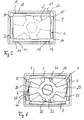
- Die Funktion des Spreizelementes 2 zeigen die Figuren 5 und 6. Wie in Figur 5 gezeigt, kann das Spreizelement 2 leicht in das Halteelement 1 eingesteckt werden. In dieser Einsteckposition liegen die größeren Flügel 29, 30 etwa diagonal im Halteelement 1.
- Das Verbindungsstück aus Spreizelement 2 und Halteelement 1 wird nun in das Hohlprofil 9 hineingesteckt und hierbei bilden die Erhebungen 10 bis 21 die Anlagefläche zwischen dem Halteelement 1 und dem Hohlprofil 9.
- Anschließend wird mit einem Sechskantschlüssel, der in die Sechskantbohrung 28 eingesetzt wird, das Spreizelement um etwa 20 Grad im Uhrzeigersinn um die Achse der Bohrung 28 gedreht. Die konkaven Seiten 33, 35 und 34, 36 der Flügel 29, 30 und 31, 32 drücken dabei gegen die Innenseite der Seitenwände 4, 5, 6, 7, wodurch die Seitenwände nach Außen gegen die Innenseite des Hohlprofils 9 gedrückt werden.
- Das Spreizelement 2 wird solange um die Achse der Bohrung 28 gedreht bis eine ausreichend feste Anlage des Halteelementes 1 am Hohlprofil 9 erzeugt ist.
- Ein Zurückgleiten des Spreizelementes entgegen der durchgeführten Drehung wird durch Rastelemente 46 an der Seite 33 mindestens eines Flügels des Spreizelementes 2 verhindert, die mit einem vorstehenden Element 47 an der Innenseite einer Seitenwand 6 zusammenwirken. Im vorliegenden Fall ist als Rasteinrichtung 46, 47 eine sperrende Verzahnung vorgesehen.
- Um eine leichte Drehung des Spreizelementes 3 im Halteelement 1 zu ermöglichen, sind an der Innenseite der Wände 4, 5, 6, 7 des Halteelementes konkave Ausnehmungen vorgesehen, die als Gegenstück mit den Flächen 33, 34, 35, 36 des Spreizelementes 3 zusammenwirken.
Claims (8)
- Verbindungselement (3) für ein Hohlteil (9) mit einem weiteren Teil im Tür- und Fensterbau mit einem Halteelement (1), das in das Hohlteil (9) in Richtung der Achse des Halteelementes (44) einsteckbar ist und einem Spreizelememt (2), das das Halteelement (1) gegen das Hohlteil (9) drückt, wobei die innere Form des Halteelementes (1) und die äußere Form des Spreizelementes (2) so aufeinander abgestimmt sind, daß durch Drehen des Spreizelementes (2) relativ zum Halteelement (1) eine feste Verbindung zwischen Halteelement (1) und Hohlteil (9) entstehen kann, dadurch gekennzeichnet, daß das Spreizelement (2) eine in Richtung der Achse (44) des Halteelements (1) verlaufende Innenvielkantfläche aufweist und die feste Verbindung durch Drehen des Spreizelementes (2) um die Achse (44) des Hohlteils (9) entstehen kann.
- Verbindungselement nach Anspruch 1, dadurch gekennzeichnet, daß das Spreizelement (2) mindestens eine bogenförmige Fläche (33, 34, 35, 36) aufweist, die mit einer entsprechenden bogenförmigen Fläche am Halteelement (1) zusammenwirkt.
- Verbindungselement nach einem der vorhergehenden Ansprüche, dadurch gekennzeichnet, daß am Spreizelement (2) und/oder am Halteelement (1) Rastmittel (46, 47) vorgesehen sind.
- Verbindungselement nach einem der vorhergehenden Ansprüche, dadurch gekennzeichnet, daß das Spreizelement (2) eine Durchbohrung (28) in Richtung der Achse (44) des Halteelementes (1) aufweist.
- Verbindungselement nach einem der vorhergehenden Ansprüche, dadurch gekennzeichnet, daß die äußere Form des Halteelementes (1) der inneren Form des Hohlteils (9) angepaßt ist.
- Verbindungselement nach einem der vorhergehenden Ansprüche, dadurch gekennzeichnet, daß die äußere Form des Halteelementes (1) kleine Erhebungen (10-21) aufweist, die die Verbindungsfläche zwischen Halteelement (1) und Hohlteil (9) bilden.
- Verbindungselement nach einem der vorhergehenden Ansprüche, dadurch gekennzeichnet, daß das Spreizelement (2) und das Halteelement (1) Teile eines Eckverbinders sind.
- Verbindungselement nach Anspruch 7, dadurch gekennzeichnet, daß das Halteelement (1) eine Bohrung oder eine Vertiefung (43) auf der Achse des entsprechenden Halteelementes des Eckverbinders aufweist.
Priority Applications (1)
| Application Number | Priority Date | Filing Date | Title |
|---|---|---|---|
| DE29823819U DE29823819U1 (de) | 1997-08-12 | 1998-07-31 | Verbindungselement für ein Hohlteil mit einem weiteren Teil im Tür- und Fensterbau |
Applications Claiming Priority (2)
| Application Number | Priority Date | Filing Date | Title |
|---|---|---|---|
| DE19734875A DE19734875C2 (de) | 1997-08-12 | 1997-08-12 | Verbindungselement für ein Hohlteil mit einem weiteren Teil im Tür- und Fensterbau |
| DE19734875 | 1997-08-12 |
Publications (2)
| Publication Number | Publication Date |
|---|---|
| EP0897047A1 EP0897047A1 (de) | 1999-02-17 |
| EP0897047B1 true EP0897047B1 (de) | 2007-03-21 |
Family
ID=7838724
Family Applications (1)
| Application Number | Title | Priority Date | Filing Date |
|---|---|---|---|
| EP98114395A Expired - Lifetime EP0897047B1 (de) | 1997-08-12 | 1998-07-31 | Verbindungselement für ein Hohlteil mit einem weiteren Teil im Tür- und Fensterbau |
Country Status (4)
| Country | Link |
|---|---|
| EP (1) | EP0897047B1 (de) |
| CZ (1) | CZ249298A3 (de) |
| DE (2) | DE19734875C2 (de) |
| PL (1) | PL195946B1 (de) |
Families Citing this family (4)
| Publication number | Priority date | Publication date | Assignee | Title |
|---|---|---|---|---|
| DE19809482C2 (de) * | 1998-03-06 | 2000-05-31 | Niemann Hans Dieter | Schweißeckverbinder von Hohlkammerprofilen |
| DE19842978C1 (de) * | 1998-09-19 | 2000-01-13 | Deflex Dichtsysteme Gmbh | Verbindungselement für Rahmenprofile |
| DE29821523U1 (de) * | 1998-12-02 | 2000-04-13 | Niemann, Hans Dieter, 50169 Kerpen | Schweißeckverbinder |
| DE10109718C1 (de) * | 2001-02-28 | 2002-07-18 | Grundmeier Kg | Eckverbinder |
Family Cites Families (14)
| Publication number | Priority date | Publication date | Assignee | Title |
|---|---|---|---|---|
| DE7200009U (de) * | 1972-04-13 | Aluminium-Walzwerke Singen Gmbh | Lösbare Eckverbindungsvorrichtung für Hohlprofile | |
| DE1013410B (de) * | 1954-02-03 | 1957-08-08 | Ver Leichtmetallwerke Gmbh | Eckverbindung fuer Hohlprofile, insbesondere fuer Fenster- und Tuerrahmen |
| US2996159A (en) * | 1958-06-02 | 1961-08-15 | Ralph T Casebolt | Miter joint |
| GB993761A (en) * | 1961-12-21 | 1965-06-02 | Hyde & Partners Ltd | Improvements relating to structural members and to frameworks embodying such members |
| FR1497682A (fr) * | 1965-09-14 | 1967-10-13 | élément de raccord pour le raccordement, entre eux, de profilés creux | |
| AT297289B (de) * | 1968-04-01 | 1972-03-27 | Wilfried Suessmilch | Winkellasche zur lösbaren Eckverbindung von Hohlprofilen |
| FR2122006A5 (de) * | 1971-01-14 | 1972-08-25 | Sidem | |
| DE2130639A1 (de) * | 1971-06-21 | 1972-12-28 | Metallbau Koelble Gmbh | Eckverbindung,insbesondere fuer Fenster-,Tuerrahmen od.dgl. |
| AU563550B2 (en) * | 1983-12-21 | 1987-07-16 | Warr, M.G. | Picture framing system |
| GB8501297D0 (en) * | 1985-01-18 | 1985-02-20 | Hara J B O | Joint for connecting tube/rod members |
| DE3745029C2 (de) * | 1987-04-13 | 1996-01-04 | Huels Troisdorf | Eckverbinder sowie Verfahren zum Verbinden zweier auf Gehrung geschnittener Hohlkammerprofile |
| FR2618862B1 (fr) * | 1987-07-27 | 1989-10-27 | Hassid Jean Pierre | Dispositif d'assemblage de tubes ou analogues comportant un logement en creux de forme cylindrique ou analogue |
| DE8809311U1 (de) * | 1988-07-21 | 1988-09-01 | Grotefeld, Hans Dieter, 4970 Bad Oeynhausen | Eckverbinder aus Kunststoff |
| GB2272013B (en) * | 1992-11-03 | 1996-01-03 | Solite Impex Pte Limited | Lockable frames formed from metal extrusions |
-
1997
- 1997-08-12 DE DE19734875A patent/DE19734875C2/de not_active Expired - Fee Related
-
1998
- 1998-07-31 DE DE59813948T patent/DE59813948D1/de not_active Expired - Lifetime
- 1998-07-31 EP EP98114395A patent/EP0897047B1/de not_active Expired - Lifetime
- 1998-08-07 CZ CZ982492A patent/CZ249298A3/cs unknown
- 1998-08-11 PL PL327949A patent/PL195946B1/pl unknown
Also Published As
| Publication number | Publication date |
|---|---|
| CZ249298A3 (cs) | 1999-03-17 |
| DE59813948D1 (de) | 2007-05-03 |
| PL327949A1 (en) | 1999-02-15 |
| PL195946B1 (pl) | 2007-11-30 |
| EP0897047A1 (de) | 1999-02-17 |
| DE19734875C2 (de) | 2003-02-06 |
| DE19734875A1 (de) | 1999-02-18 |
Similar Documents
| Publication | Publication Date | Title |
|---|---|---|
| DE19646988C5 (de) | Beschlag für ein Fenster | |
| DE29701099U1 (de) | Stiftförmiges Halteelement für ein orthopädisches Haltesystem | |
| DE69410877T2 (de) | Schloss, bestehend aus einem Schlüssel und einem Zylinderschloss | |
| EP0335069A1 (de) | Flachschlüssel für Zylinderschlösser sowie zugehöriges Zylinderschloss | |
| CH671429A5 (de) | ||
| DE69904408T2 (de) | Schlüssel mit bewegbarem stift, sicherheitsdrehzylinder und damit ausgerüstetes schloss | |
| EP0897047B1 (de) | Verbindungselement für ein Hohlteil mit einem weiteren Teil im Tür- und Fensterbau | |
| DE20004943U1 (de) | Verriegelungsvorrichtung mit pilzförmigem Zapfen | |
| DE3202253C2 (de) | ||
| DE202020004473U1 (de) | Einstellbares Scharnier für Fenster- oder Türbefestigungen | |
| EP0052803A2 (de) | Scharnierarm mit Befestigungsplatte | |
| DE19949695A1 (de) | Vorrichtung zum Befestigen oder Verbinden von Bauteilen | |
| EP1635075B1 (de) | Verbindungsvorrichtung | |
| DE69315107T2 (de) | Einstellbarer Abstandhalter für den Einbau von Tür- und Fensterrahmen | |
| CH646488A5 (de) | Aufhaengevorrichtung von einem verschiebbaren fluegel einer schiebetrennwand. | |
| EP1342926B1 (de) | Befestigungsvorrichtung | |
| DE8534096U1 (de) | Zylinderschloß mit einer Nachschließsicherung | |
| EP3913183A1 (de) | Statikteil für einen rollladenkasten | |
| DE29711966U1 (de) | Türarretierungsanordnung | |
| DE29617518U1 (de) | Türfeststeller | |
| DE19502362C2 (de) | Positionierungseinrichtung für Beschlagteile | |
| DE19717116B4 (de) | Drehlager | |
| EP1760229B1 (de) | Schliesszylinder, insbesondere Profilzylinder, für eine Schliessvorrichtung wie z.B. ein Türschloss | |
| EP1749953A2 (de) | Klemmstift | |
| EP3563009B1 (de) | Wandschirmverbindungseinrichtung zum gelenkigen verbinden von wandschirmen und wandschirmanordnung |
Legal Events
| Date | Code | Title | Description |
|---|---|---|---|
| PUAI | Public reference made under article 153(3) epc to a published international application that has entered the european phase |
Free format text: ORIGINAL CODE: 0009012 |
|
| AK | Designated contracting states |
Kind code of ref document: A1 Designated state(s): DE FR |
|
| AX | Request for extension of the european patent |
Free format text: AL;LT;LV;MK;RO;SI |
|
| 17P | Request for examination filed |
Effective date: 19990805 |
|
| AKX | Designation fees paid |
Free format text: DE FR |
|
| 17Q | First examination report despatched |
Effective date: 19991115 |
|
| GRAG | Despatch of communication of intention to grant |
Free format text: ORIGINAL CODE: EPIDOS AGRA |
|
| GRAG | Despatch of communication of intention to grant |
Free format text: ORIGINAL CODE: EPIDOS AGRA |
|
| GRAH | Despatch of communication of intention to grant a patent |
Free format text: ORIGINAL CODE: EPIDOS IGRA |
|
| GRAH | Despatch of communication of intention to grant a patent |
Free format text: ORIGINAL CODE: EPIDOS IGRA |
|
| 17Q | First examination report despatched |
Effective date: 19991115 |
|
| 19A | Proceedings stayed before grant |
Effective date: 20000710 |
|
| 19F | Resumption of proceedings before grant (after stay of proceedings) |
Effective date: 20070102 |
|
| GRAA | (expected) grant |
Free format text: ORIGINAL CODE: 0009210 |
|
| AK | Designated contracting states |
Kind code of ref document: B1 Designated state(s): DE FR |
|
| RIN2 | Information on inventor provided after grant (corrected) |
Inventor name: DER ERFINDER HAT AUF SEINE NENNUNG VERZICHTET. |
|
| REF | Corresponds to: |
Ref document number: 59813948 Country of ref document: DE Date of ref document: 20070503 Kind code of ref document: P |
|
| ET | Fr: translation filed | ||
| PLBE | No opposition filed within time limit |
Free format text: ORIGINAL CODE: 0009261 |
|
| STAA | Information on the status of an ep patent application or granted ep patent |
Free format text: STATUS: NO OPPOSITION FILED WITHIN TIME LIMIT |
|
| 26N | No opposition filed |
Effective date: 20071227 |
|
| REG | Reference to a national code |
Ref country code: DE Ref legal event code: R082 Ref document number: 59813948 Country of ref document: DE Representative=s name: AXEL DRAUDT, DE |
|
| REG | Reference to a national code |
Ref country code: DE Ref legal event code: R082 Ref document number: 59813948 Country of ref document: DE Representative=s name: DRAUDT, AXEL, DIPL.-ING., DE Effective date: 20110715 Ref country code: DE Ref legal event code: R081 Ref document number: 59813948 Country of ref document: DE Owner name: ROTO GLUSKE-BKV GMBH, DE Free format text: FORMER OWNER: FA. JOACHIM GLUSKE, 42281 WUPPERTAL, DE Effective date: 20110715 |
|
| REG | Reference to a national code |
Ref country code: FR Ref legal event code: PLFP Year of fee payment: 19 |
|
| REG | Reference to a national code |
Ref country code: FR Ref legal event code: PLFP Year of fee payment: 20 |
|
| PGFP | Annual fee paid to national office [announced via postgrant information from national office to epo] |
Ref country code: FR Payment date: 20170724 Year of fee payment: 20 Ref country code: DE Payment date: 20170728 Year of fee payment: 20 |
|
| REG | Reference to a national code |
Ref country code: DE Ref legal event code: R071 Ref document number: 59813948 Country of ref document: DE |