EP0898210A2 - Verfahren und Vorrichtung zum selbst-fixierenden Druck von einem ferroelektrischen Aufzeichnungsmittel - Google Patents
Verfahren und Vorrichtung zum selbst-fixierenden Druck von einem ferroelektrischen Aufzeichnungsmittel Download PDFInfo
- Publication number
- EP0898210A2 EP0898210A2 EP98115408A EP98115408A EP0898210A2 EP 0898210 A2 EP0898210 A2 EP 0898210A2 EP 98115408 A EP98115408 A EP 98115408A EP 98115408 A EP98115408 A EP 98115408A EP 0898210 A2 EP0898210 A2 EP 0898210A2
- Authority
- EP
- European Patent Office
- Prior art keywords
- toner
- recording medium
- image
- carrier liquid
- vacuum
- Prior art date
- Legal status (The legal status is an assumption and is not a legal conclusion. Google has not performed a legal analysis and makes no representation as to the accuracy of the status listed.)
- Ceased
Links
Images


Classifications
-
- G—PHYSICS
- G03—PHOTOGRAPHY; CINEMATOGRAPHY; ANALOGOUS TECHNIQUES USING WAVES OTHER THAN OPTICAL WAVES; ELECTROGRAPHY; HOLOGRAPHY
- G03G—ELECTROGRAPHY; ELECTROPHOTOGRAPHY; MAGNETOGRAPHY
- G03G15/00—Apparatus for electrographic processes using a charge pattern
- G03G15/14—Apparatus for electrographic processes using a charge pattern for transferring a pattern to a second base
- G03G15/16—Apparatus for electrographic processes using a charge pattern for transferring a pattern to a second base of a toner pattern, e.g. a powder pattern, e.g. magnetic transfer
- G03G15/169—Apparatus for electrographic processes using a charge pattern for transferring a pattern to a second base of a toner pattern, e.g. a powder pattern, e.g. magnetic transfer with means for preconditioning the toner image before the transfer
-
- G—PHYSICS
- G03—PHOTOGRAPHY; CINEMATOGRAPHY; ANALOGOUS TECHNIQUES USING WAVES OTHER THAN OPTICAL WAVES; ELECTROGRAPHY; HOLOGRAPHY
- G03G—ELECTROGRAPHY; ELECTROPHOTOGRAPHY; MAGNETOGRAPHY
- G03G15/00—Apparatus for electrographic processes using a charge pattern
- G03G15/06—Apparatus for electrographic processes using a charge pattern for developing
- G03G15/10—Apparatus for electrographic processes using a charge pattern for developing using a liquid developer
- G03G15/104—Preparing, mixing, transporting or dispensing developer
-
- G—PHYSICS
- G03—PHOTOGRAPHY; CINEMATOGRAPHY; ANALOGOUS TECHNIQUES USING WAVES OTHER THAN OPTICAL WAVES; ELECTROGRAPHY; HOLOGRAPHY
- G03G—ELECTROGRAPHY; ELECTROPHOTOGRAPHY; MAGNETOGRAPHY
- G03G15/00—Apparatus for electrographic processes using a charge pattern
- G03G15/14—Apparatus for electrographic processes using a charge pattern for transferring a pattern to a second base
- G03G15/16—Apparatus for electrographic processes using a charge pattern for transferring a pattern to a second base of a toner pattern, e.g. a powder pattern, e.g. magnetic transfer
- G03G15/1605—Apparatus for electrographic processes using a charge pattern for transferring a pattern to a second base of a toner pattern, e.g. a powder pattern, e.g. magnetic transfer using at least one intermediate support
- G03G15/161—Apparatus for electrographic processes using a charge pattern for transferring a pattern to a second base of a toner pattern, e.g. a powder pattern, e.g. magnetic transfer using at least one intermediate support with means for handling the intermediate support, e.g. heating, cleaning, coating with a transfer agent
-
- G—PHYSICS
- G03—PHOTOGRAPHY; CINEMATOGRAPHY; ANALOGOUS TECHNIQUES USING WAVES OTHER THAN OPTICAL WAVES; ELECTROGRAPHY; HOLOGRAPHY
- G03G—ELECTROGRAPHY; ELECTROPHOTOGRAPHY; MAGNETOGRAPHY
- G03G15/00—Apparatus for electrographic processes using a charge pattern
- G03G15/14—Apparatus for electrographic processes using a charge pattern for transferring a pattern to a second base
- G03G15/16—Apparatus for electrographic processes using a charge pattern for transferring a pattern to a second base of a toner pattern, e.g. a powder pattern, e.g. magnetic transfer
- G03G15/1665—Apparatus for electrographic processes using a charge pattern for transferring a pattern to a second base of a toner pattern, e.g. a powder pattern, e.g. magnetic transfer by introducing the second base in the nip formed by the recording member and at least one transfer member, e.g. in combination with bias or heat
- G03G15/167—Apparatus for electrographic processes using a charge pattern for transferring a pattern to a second base of a toner pattern, e.g. a powder pattern, e.g. magnetic transfer by introducing the second base in the nip formed by the recording member and at least one transfer member, e.g. in combination with bias or heat at least one of the recording member or the transfer member being rotatable during the transfer
-
- G—PHYSICS
- G03—PHOTOGRAPHY; CINEMATOGRAPHY; ANALOGOUS TECHNIQUES USING WAVES OTHER THAN OPTICAL WAVES; ELECTROGRAPHY; HOLOGRAPHY
- G03G—ELECTROGRAPHY; ELECTROPHOTOGRAPHY; MAGNETOGRAPHY
- G03G2215/00—Apparatus for electrophotographic processes
- G03G2215/16—Transferring device, details
- G03G2215/1604—Main transfer electrode
- G03G2215/1614—Transfer roll
-
- G—PHYSICS
- G03—PHOTOGRAPHY; CINEMATOGRAPHY; ANALOGOUS TECHNIQUES USING WAVES OTHER THAN OPTICAL WAVES; ELECTROGRAPHY; HOLOGRAPHY
- G03G—ELECTROGRAPHY; ELECTROPHOTOGRAPHY; MAGNETOGRAPHY
- G03G2215/00—Apparatus for electrophotographic processes
- G03G2215/16—Transferring device, details
- G03G2215/1676—Simultaneous toner image transfer and fixing
- G03G2215/168—Simultaneous toner image transfer and fixing at the first transfer point
Definitions
- the invention relates to a method according to claim 1 and to a device according to claim 20.
- the invention relates to the field of electrostatography and, in particular, to a Method and device for self-fixing electrographic Printing processes that work at high speeds.
- Electrographic printing is a well known printing process in which an electrostatic latent image is treated to be electrostatic attracts marking particles contained in a toner.
- the toner can be either a dry toner or a liquid toner.
- the electrographic Printing is particularly useful when only one is relative small number of prints is required or if the image to be printed is different changes frequently or when part of the image to be printed changes sequentially must become.
- Dry toner powders have a number of disadvantages when encountered with such Printing processes are used.
- For high printing speeds, for Long duration printing process is the analysis of the cost per page of special meaning.
- the cost of melting the Images on paper or any other substrate add significantly to that running costs of such a printer.
- Other disadvantages include that Cost of the entire maintenance of the printing device and the cost of the Dry toner powder.
- toner particles can be dispersed in insulating or non-polar liquids are.
- Such toner particles usually include a color-forming one Substance, for example pigments, which have been ground in connection with or combined in another way with dispersing resins or lacquers or similar.
- means for controlling the polarity or Agents for aligning the charges are usually attached to the polarity adjust and the ratio between charge and mass of the toner particles adjust.
- Such dispersed materials are known as liquid toners or as a liquid developer. When used, a liquid developer is applied to the Surface of a carrier applied, which carries a charge pattern to a develop electrostatic image on the support.
- the developed latent image is fixed on the surface, especially by means of a transfer to a subsequent substrate surface, usually heating to temperatures above room temperature takes place in order to melt the toner image onto the substrate.
- a variety of procedures can be used used to perform such a fixing step on the substrate achieve, for example by means of IR or UV radiation, by means of a Solvent vapor or with a variety of other techniques or Connections using such techniques, usually by those skilled in the art to be used.
- the above mentioned need Process to fix a toner image on a substrate high Power consumption. They can also be ecologically undesirable or be slow or have several of these disadvantages.
- Liquid toner particles can also be used in conjunction with fixing materials, which are usually, but not necessarily are thermoplastic polymeric materials.
- fixing materials which are usually, but not necessarily are thermoplastic polymeric materials.
- Such fixing materials if they are incorporated within the toner, other physical Properties adversely affect the mobility of such toner particles by making such toner particles unsuitable for use in the To use high speed printing by means of electrographic processes can.
- an electrostatic developer liquid discloses in which a wax is dispersed in the liquid carrier so that the Developer is self-fixing at room temperature.
- U.S. Patent 4,507,377 is a developer that uses a compatible mixture of at least one polyester resin and at least one Polyester plasticizing material. This mixture leads to a self-fixing liquid developer for the electrographic process.
- compositions and the self-fixing additive in them limit the electrophoretic development rate of the liquid toner particles. In high speed electrographic printing processes, such compositions would not be able to produce adequate density and have self-fixing characteristics if an increased printing speed greater than 1 ms -1 was used.
- U.S. Patent 3,907,423 teaches a method and apparatus for Extract excess developer liquid to remove the solvent by means of a roller used to carry out the extraction process reduce.
- U.S. Patent 4,286,039 teaches the use of a deformable roller Polyurethane as a squeeze or peel roller.
- the liquid toner is of the type that is highly mobile Contains toner particles when the liquid toner is at least partially from them removed, an adherent, i.e. H. firmly adhering and firmly attached shelf form a document.
- the toner is applied to the recording medium by means of a System applied donor roller.
- the invention can additionally comprise a further step, which between the Steps b) and c) is inserted, the developed image on a Intermediate carrier is transferred before the developed image on the substrate, d. H. the substrate is transferred.
- the invention can additionally comprise a further step, which consists in that excess carrier liquid is removed from the developed image by means for a second vacuum extraction process on the intermediate recording medium is inserted.
- the invention may further include a further step, which is therein there is a layer of the liquid carrier on the intermediate recording medium is applied before the developed image of this is transmitted.
- a further step can also be provided after the implementation of the Step c) by cleaning the recording medium, the Carrier liquid is applied by means of a cleaning unit.
- Excess carrier liquid and superfluous are preferred Toner material that by means of the vacuum extraction device or by means of the second vacuum extractant was removed, recycled.
- the toner material has the property that it does not clump or clump, even if it does has been recycled. Rather, the recycled liquid toner can be used directly Liquid toner can be reused.
- the invention can preferably be used for high-speed printing processes for printing a continuous printing material web.
- the printing speed according to this invention can reach printing speeds of up to 10 ms -1 .
- the vacuum extractant or another vacuum extractant can operated at a vacuum of 1 to 80 kPa.
- the latent image is digitally displayed on the Recording medium generated.
- the printing method according to the invention can at high Print speeds through a self-fixing material in multi-color printing be carried out with a plurality of printing stations.
- the means for returning the liquid toner preferably comprise one Device with a donor roller.
- the device may additionally comprise an intermediate transfer means which between the recording medium and the recording station (Transfer station) is arranged.
- the means for removing the excess carrier liquid from one developed latent image on the recording medium preferably comprises Vacuum extractant.
- a vacuum extraction device can be used to remove excess To remove carrier liquid from the developed latent image on which Intermediate recording member may be provided.
- the vacuum extraction device and the further extraction device can create a vacuum between 1 and 80 kPa.
- the vacuum extraction device and the further extraction device can comprise an elongated slot through which the vacuum is drawn and the transversely to the transport direction of the recording medium and the Intermediate recording medium, the gap width between the respective transmission links between 0.05 and 5 mm and where it is a Has a width of 0.5 to 5 mm.
- the recording station can have a transfer roller include.
- the means to apply the electrostatic latent image to the recording medium generate can include digital means.
- the device may further comprise a cleaning unit, which is suitable for to clean the recording medium and / or a cleaning unit which is suitable to clean the intermediate transmission member.
- the cleaning unit which is suitable for cleaning the recording medium can also be adapted to apply a layer of the carrier liquid to the Apply recording medium.
- the cleaning unit which is suitable for the recording medium clean can also be adjusted to a layer of the carrier liquid onto the intermediate recording medium.
- the cleaning unit according to these embodiments of the invention can driven cleaning roller include and means for applying the Carrier liquid on the respective recording medium before this Cleaning roller and the extractant to remove excess Carrier liquid reached by the respective recording medium.
- the device can additionally contain recycled toner material and an air separation device include.
- the separator preferably comprises a Housing that contains an inlet for the extracted toner and air, as well a baffle disposed around the inlet and one Air outlet, and a toner outlet located outside the deflector with the air outlet connected to a source of reduced pressure is.
- the high speed electrographic printing device may be one Multi-color printing direction and therefore a variety of printing stations include as characterized above.
- the present invention is particularly suitable for repeated use to tone latent image that is on or above the surface of a ferroelectric recording medium is available and the use of suitable liquid toners, which have a variety of disadvantages of To overcome the state of the art.
- suitable liquid toners which have a variety of disadvantages of To overcome the state of the art.
- no melting and Fixing the toner deposits requires, which is why such deposits are wear-free to the extent that it is for normal handling and Procedural purposes is expected.
- a self-regulating electrographic printing machine which is capable of working at any printing speed which is required and which is not limited by any speed. It can operate at a low electrographic print speed, usually 0.1 ms -1 to a high electrographic print speed, usually 10 ms -1 or any incremental speed between the two speeds, although a print speed of 1 ms -1 and 5 ms -1 or an incremental speed between these two speeds is preferred.
- the toner is loaded while it is on the developer roller
- the funds for the development process are loaded by: create a waveform in the liquid toner solution.
- Such a toner process by means of toning by creating a hydraulic meniscus is disclosed in U.S. Patent 5,213,931.
- Such toners are typically characterized by the structure in which the Pigments are encased or encapsulated by associated polymers in which Way that the surface of the particles is substantially smooth, however a suitable selection of such polymers with regard to the properties of a Carrier has taken place and that the particle surface in some way shows a sticky character.
- Another advantage of such a toner system is that it is recycled Toner can be reused without resins in the carrier that are in Connection with other components in the toner composition Balance in the toner liquid.
- a toner such as that described in U.S. Patent 5,418,104 allows high Agility during meniscus tone, as described in U.S. Patent 5,213,913 is disclosed, which is due to the smooth surface structure. If however, excess carrier liquid from the toner deposit on the Recording medium is removed, the not yet present discretely Particles to become adherent and to connect with each other, so that they form a network which enables an efficient transfer of the Toner particles allowed without a shift or rearrangement more individual Toner particles takes place, whereby a high image resolution is achieved and whereby when the now sticky network of particles on the printing Substrate is applied, an almost instantaneous secure binding of the said network of particles on the printing substrate is achieved without that a subsequent fixing step is necessary.
- toner materials are contemplated useful in this invention, the substantially discrete toner particles in one Detect suspension, which is a dispersant with low electrical Has conductivity to an electrical connection of the toner particles prevent, wherein the discrete toner particles comprise pigmentary articles from one layer of an electrically insulating thermoplastic polymer and one Plasticizing material are surrounded, whereby the toner particles in the occur essentially discretely in their form and none at all Have surface production so that mechanical connections be prevented between the particles; that electrically insulating thermoplastic polymer for the toner material is selected from one Chemical group, the acrylics, acrylic copolymers, polyethylene and Polyethylene vinyl acetate copolymers.
- the toner particles which comprise pigment particles, in turn, through a layer an electrically insulating thermoplastic polymer and one Plasticizers are surrounded, are within a dispersant or a carrier fluid kept in suspension when an external electrical Field is applied, as in a ferroelectric recording medium is provided, wherein it is intensified by the donor medium, so that the Toner particles quickly move toward and onto the latent image deposit this.
- This toner particle movement with a high Particle mobility takes place is a fundamental requirement for everyone High speed printing using an electrographic process.
- the present invention takes advantage of the particles as described in the US patent 5,418,104, wherein the toner particles have a well-defined im have essentially spherical geometry without a network of particles arises that would significantly hinder the movement of the toner particles, whereby the mobility of the toner particles decreased dramatically.
- the removal of excess carrier liquid can be accomplished by a variety of different means, including vacuum suction means as disclosed in U.S. Patent 5,023,665, or by the reserving roller in U.S. Patent 3,907,423, or by a solvent limiting device, such as those described in U.S. Pat U.S. Patent 3,722,994.
- a device which comprises a vacuum suction unit, which enables excellent control of the quantity of carrier liquid which is removed at increased printing speeds, that is to say at speeds of more than 1 ms -1 , which causes the network formation of the toned Image forming toner particles is supported so that an almost dry transfer of the image can be achieved on the receiving medium and excess carrier liquid can be completely recovered and added to the dispersed toner in such a way that the working strength necessary for the toner is restored can be effected, wherein a desired concentration of the solids dissolved in the liquid is effected so that the carrier liquid can be reused.
- the carrier liquid is virtually an element of the printing device and is not to be regarded as a consumable, although of course small amounts of said carrier liquid are lost from the device, as is understood by those skilled in the art.
- Another advantage of using a vacuum suction device is that stray toner particles can be removed along with the excess carrier liquid on those areas of the electrostatic latent image where there is no charge, thereby reducing the strength of the background fog on the final image .
- a particular advantage when using a ferroelectric Recording medium is that the persistent internal polarization, the carries the latent image, allows a high vacuum, reducing the amount of Carrier fluid can be limited with the image deposit on the said recording medium is connected so that only a minor Amount of carrier liquid is carried out to the printing substrate, whereby environmental and cost considerations are fulfilled.
- a very fast one Adherence of the image deposited on the final print substrate reached so that a subsequent further treatment of the printing material is possible is the way it’s in print shops, for example in terms of winding, Cutting, collating, etc. without a fuser or any System must be provided, for example the use of radiation any frequency, including blackbody radiation, that should be noticed on the toner deposits or should touch them and / or on the final substrate in any way; this means the bond the toner particles on the substrate, as described here, on a Binding at ambient temperature without the need for to apply external forces including such chemical nature. It is coming added that when the printing is completed, the adhered image is such Fixier exercises the usual care requirements regarding Wear, tear, skimmed oil, crushing behavior and Erase head resistance corresponds.
- an intermediate one can be used Recording medium between the developing roller and the final one Arrange the substrate.
- the selection criterion for suitable materials must be considered with regard to the surface energy so that no toner on the intermediate recording medium is bound.
- the preferred liquid toner has such a physical nature that the outer components of the encapsulated and described above surrounding pigment particles that are made according to the US patent 5,418,104, are normally dispersed in the carrier liquid, such as for example in Isopar L manufactured by Exxon Corporation, or the like.
- the invention describes a method of printing in which Liquid toners are used, with the latent image on the ferroelectric Recording medium is toned and excess carrier liquid removed and with the toned image subsequently on a suitable substrate is transferred, the image being bound directly to the substrate without that an additional fixation device is necessary.
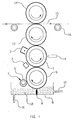
- FIG. 1 described an electrographic printer for high speeds which comprises a recording medium 1 with a write head 2, wherein the print head 2 is adapted to an electrostatic latent image on the Form recording medium 1.
- a device 3 for enhancing the charge of the latent image enhances the Charge on the recording medium 1.
- a donor roller 5 collects toner from a toner bath 9 when it turns moved over a weir 8. Excess toner is passed through a roller 6 removed, which is cleaned by a scratch 7. Through a feed line 10 the toner is supplied to the toner bath 9 and through a discharge line 11 it becomes removed for recycling.
- a thin layer of the liquid toner is around the donor roller 5 applied and from this to the recording medium 1, where the electrostatic electrical image tones.
- the toned electrostatic latent image is on the recording medium 1 transported around, and excess toner liquid and excess toner are removed by a vacuum head 4 before the toned image on a Intermediate roller 13, d. H. a transfer cylinder is transmitted.
- the toned Image is guided around the intermediate roller 13 until it is on a Printing material web or another substrate 15 is transmitted, which by a gap between the intermediate roller 13 and a transfer roller 14, i.e. H. a pressure cylinder.
- the printing material web 15 is about Carrying rollers 16 transported.
- the method for Generation of the electrostatic image and toning of the electrostatic Image the same as in Fig. 1; however after the electrostatic image on the Intermediate roller 13 has been transferred, a second vacuum head 17th used to remove more of the excess carrier fluid before the image is transferred to the printing material web 15.
- a cleaning device 18 is used on the intermediate roller 13 to add remaining toner remove before the intermediate roller 13 the developed image of the Recording medium 1, i.e. H. the recording roller 1.
- Fig. 3 shows a structure for the direct transfer of developed images to the Printing material web 15.
- the print head 2 generates a latent image on the recording roller 1, this is one of the Contrast enhancing device 3 arranged to the latent image on the to strengthen the ferroelectric surface of the recording roller 1.
- the vacuum head 4 removes the largest Proportion of carrier fluid and scattered toner particles before the developed Image is transferred to the printing material web 15, which is via a transfer roller 19th is unrolled.
- the recording roller 1 is then by the Cleaning device 18 cleaned before the device 3 the picture again charges.
- the Print head 2 When using the ferroelectric recording roller 1, the Print head 2 the latent image on the platen 1 under none at all Circumstances change, a lot of exact duplicates of the image must be made to be produced.
- the write head 2, however, is equipped so that it all Part or part of the electrostatic image can change so that it is e.g. Legs consecutive number of digits printed on the copy of an image can be, which remains otherwise unchanged.
- ferroelectric recording roller consist of the ability to maintain high-resolution latent images and the ability to get a gray scale and a continuous one To maintain sound reproduction, as in the field of graphic Technology.
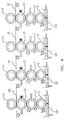
- Fig. 4 shows a structure for printing on a printing material web 15, which also is suitable for color printing.
- Each stage has a donor roller 5, which is in a toner bath 20, 21, 22, 23rd immersed, a recording roller 1, an intermediate roller 13 and a Transfer roller 14, wherein the printing material web 15 through the gap between the Transfer roller 14 and the intermediate roller 13 passes through.
- a toner of a first color creates an electrostatic image that matches the first Color is toned and is transferred to the printing material web 15.
- toner 21 forms an electrostatic image with a second Color that is transferred to the printing material web 15, a correct one Register between the first and the second stage is set. Following Inks are transferred from the toner tanks 22 and 23, likewise the register between the individual transmission stages is set correctly, so that the printing material web 15, after all four colors have been printed, has a fully developed picture.
- the colors are preferably cyan, magenta, yellow and black. A Combination of these colors or any other colors can can also be used.
- the sequence of colors in the stages depends on the chemical Composition of the toner, its opacity; the preferred order
- the printing colors are yellow, blue, magenta and black, although others Color sequences can be used within the scope of the invention.
- Fig. 5 shows a schematic view of a vacuum head 4 of a type like it is used according to the present invention.
- the vacuum head 4 has a valve 25 with an opening 24 at its tip.
- a line 27 is vacuum applied and excess carrier material received by a tank 26 which is arranged inside a body 28, and is then transported on line 27 for recycling while the Vacuum is applied.
- the vacuum extraction stage 29 extracts the scattered toner particles and the carrier liquid with the help of air, the Toner particles and the carrier liquid are transported to a toner separator 30 where the carrier liquid and the toner particles are separated from the air become and wherein the liquid and the particles to a toner reservoir 31st be transported and the air through a line 30a to a source is transported for reduced pressure or vacuum.
- the toner will then become too a toner concentration control unit 33 to ensure that the toner has the appropriate working concentration, with further Toner concentrate from a toner concentrate resvervoir 32 can be added may, if the toner concentration control unit 33 determines that the toner an enrichment is required and if this to the concreting unit 34 is transported, with excess toner back to the toner reservoir 32 is transported.
- the toned image becomes too transferred to the vacuum stage and after applying a vacuum, as in stage 2 Shown to illustrate the present invention, the predominant amount of the carrier liquid 35 removed, only a very small amount a small amount remains below the toner particles.
- the vacuum process or any other process Always remove a significant amount of the excess carrier fluid Carrier liquid 35 left over the toner particles. According to the Invention can remove significantly more carrier fluid because of the ferroelectric surface carries a higher charge, so that a higher Vacuum can be applied to extract the carrier liquid 35.
- the toner particles tend to agglomerate, so that a network of particles 36 according to the invention is created while at stand the technology, the remaining carrier liquid prevents this agglomeration.
- the carrier liquid 35 acts below the coherent network of toner particles remains as a means to detach them from the recording medium 1 so that when the attached toner particles are transferred to the printing material web 15 in there is essentially no longer any carrier liquid on the surface, resulting in a leads to the current self-fixing step.
- the embodiment 7 is like that of FIG. 3, but with a intermediate transmission process with vacuum extraction available could be, where then another level between level 3 and level 4 would be present in Fig. 7.
- the ferroelectric Recording media is polarized as shown in U.S. Patent 5,191,834 so that the domain structure bears constant internal polarization corresponding to a permanent latent image, which is a repeated one Concretes allow and transfer of the toner without it being necessary is to regenerate the image for each print, which makes it very quick Printing process is enabled and a repeated raster image loading process is not is required.
- This imaging process for imaging the ferroelectric recording medium is used in this embodiment included, but other methods according to the invention Can find use.
- the persistent latent image thus formed on the surface or in Connection to the surface of the polarized ferroelectric Recording medium can be amplified, if necessary, what means that an increased potential difference between the positively polarized Image parts and the negative polarized image parts is applied, whereby the Contrast between the image and the non-image parts is increased.
- This method of contrast enhancement of the latent image allows the Using a high vacuum after the latent image is developed, because of an increased electrostatic force the toner particles on the image medium holds and also an increased electrostatic attraction of the toner particles the latent image and thereby the development speed and all subsequent steps and thus the printer speed elevated.
- the electrostatic printer described herein is full can be automated because the main controller in a print control computer can exist, the analog and digital interface options includes.
- the transfer station, the Concreting station or for example the recycling station a limited one Self-regulating unit can include the pressure control computer maintain optimal interdependency of such subunits.
- the present invention a high vacuum, so that after the vacuum pressure stage outer surface of the toner deposit substantially free of Carrier fluid is, causing the extensive formation of a network of Toner particles is enabled while deliberately allowing a certain amount of Carrier liquid is retained at or near the toner deposit, d. H. on the surface of the recording medium so that a complete Transfer the toner image to the intermediate platen or any other substrate without loss of image resolution or the integrity of the image is made possible.
- Relocation of part or all of the toned latent image after toning or during transfer and / or after transfer at high printing speeds is virtually eliminated in this embodiment.
- dislocations which are also referred to as redrawing, smearing, etc., are associated with fixed pressure surfaces; and this phenomenon becomes particularly noticeable at print speeds greater than 1 ms -1 when hydrodynamic displacement of the toned latent image can take place.
- the invention allows networks of particles of the toned latent image to be formed if the concentration of the carrier liquid on or in connection with the particles is reduced by a vacuum suction device or the like, essentially connecting a mat of interconnected particles because this can be transmitted as the only coherent whole, prevents hydrodynamic displacement of individual particles and possible trailing, blurring or blackening at high printing speeds. Therefore, the addition of hardened or densifying agents is not necessary within this device, even if printing at speeds of up to 5 ms -1 .
- the intermediate roller 13 it has been found useful found in connection with the intermediate roller 13 a device for Wetting the same with the carrier liquid to actively provide the amount of To control carrier liquid on the surface of the intermediate roller 13 to in this way the discharge of toner particles from the intermediate roller 13, i. H. from to support the surface, thereby making the transfer to the final one Substrate is improved; such a system allows an excellent transfer for a wider variety of substrates, d. H. Papers, additionally it also reduces the amount of paper dust that accumulates on the Recording medium falls, leaving the liquid toner either directly contaminated or indirectly through the system used to recycle the Carrier liquid serves.
- Such a device for wetting with the carrier liquid can also be used in the Cleaning unit can be installed.
- 8 shows an embodiment of a such cleaning unit, as used in the invention. While in operation, a body 37 belonging to the cleaning unit carries a roller 42, made of a material with open cells or a similar suitable Material is made. The roller 42 is pressed against the intermediate roller rotated by a motor 44 at a predetermined rotational speed, to scrape off any remaining toner after the transfer. The Carrier liquid passes through an inflow line 39 to a spray nozzle 38 fed, which wets or softens the toner deposit before it through the Roller 42 is scraped off.
- Excess carrier liquid is removed by a vacuum 41 removed and to a collector tank, not shown, by means of a Vacuum tube 40 sucked.
- the roller 42 is by means of a spray nozzle 43 and 45 sprayed out carrier liquid jet, the Carrier liquid is supplied through the tube 47. Remaining carrier liquid and remaining toner particles are removed from the roller 42 by the vacuum 41 away.
- the jet of carrier liquid 46 fed through tube 47 creates a remaining layer of the carrier liquid which, if required can serve as a release layer before the subsequent developed one Image is obtained from the imaging member.
- Another control of this final carrier liquid release layer is vacuum 48 with achieved additional carrier liquid, which by a not shown Collector tank is returned by means of the vacuum tube 49.
- the layer thickness the release layer is between 0.1 and 10 microns, but one Peeling layer of 0.5 to 3 microns thick is preferred.
- the cleaning unit shown above is primarily as one Device for removing unnecessary toner that is not completely on the final substrate substrate was transferred, is designed, can careful control of liquid jets and vacuum one Surprisingly well controlled layer of the carrier liquid on the surface of the Intermediate roll are generated to create a release layer. It is therefore possible not only to clean the surface of the intermediate transfer member, before another collection of developed images from the recording medium takes place there, but the layer can also act as a moistening mechanism act by a controlled layer thickness of the carrier liquid on the Intermediate roller is generated, which serves as a removable layer to a more complete transfer of the toner particles to the final substrate to achieve.
- the carrier liquid used in the cleaning unit to remove it remaining toner particles and used to create a release layer is fully recycled within the printer, with only one very minor amount of the toner liquid is lost due to evaporation, such as can be determined by the experts.
- Contaminated by toner Carrier liquid from the cleaning unit becomes a collector tank transported from where it is then passed through a variety of filters to remove the toner particles. The filtered in this way Carrier fluid then becomes a tank for storing the Carrier liquid is transported from where it returns to the cleaning unit can recirculate.
- the configuration of the vacuum system which has a negative pressure in the Vacuum head 4, as shown in Fig. 5, comprises a unit which is operated by means of compressed air in which a Venturi type system creates a negative pressure in the storage tank.
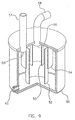
- the negative pressure is to the vacuum head 4 or the vacuum heads 4, 17 by means of a Toner separator 30 applied, as shown in Fig. 9.
- FIG 9 illustrates the toner separator as used in the invention.
- the toner separator consists of a housing 50 in which an inlet 56 the Removal of excess toner is allowed, which is from the developed image by means of the vacuum head through the supply line 58 to the input of the Toner separator has arrived.
- Deflection plates ensure the separation of the Toner particles from the air flow caused by negative pressure from the not shown storage tank via the feed line 57 and the air flow Incoming outlet 55 flow.
- the toner separated in this way that collects at the bottom of the housing 50 is not by means of a Pump shown transported from an outlet 51 to the toner reservoir.
- the vacuum system as well as all pumps referred to in the invention is taken, operated by compressed air. This system is therefore extremely fire-proof.
- the configuration of the transfer device can either be of the type for the direct transfer, with the toned latent image of the Recording medium is transported directly to the printing material, or from that with an intermediate means, whereby the toned image initially increases an intermediate transfer roller and only then to the printing material is transported.
- the latter has Embodiment, d. H. using an intermediate transfer link, turned out to be preferred because such a system has better control the amount of carrier liquid allowed with the image to be transferred is connected such that a second vacuum suction device in connection with the intermediate transfer member can be arranged if necessary is.
- electrostatic transfer is preferred, the present invention also use other methods such as, for example are known from U.S. Patent 5,342,726; however, any combination of transfer procedures can be used if desired.
- a transfer under pressure is like the professionals know a transfer under pressure from the ferroelectric Recording medium difficult in that a disturbance of the internal Polarization within the recording medium is a distortion or Can cause a change in the latent image; such a distortion or Changing a latent image is usually on repeated printing undesirable.
- a vacuum suction device is a great way to control the amount of toner liquid that is removed at increased printing speeds, for example, greater than 1 ms -1 , helping to form a network of toner particles in the toned image such that an almost dry one Transfer of the adhesive image thus formed to the recording medium can be achieved.
- Figure 10 shows a graphical representation of an example of the intensity of the vacuum used in the invention.
- the size specifications relate to an experimental vacuum head as shown in FIG. 5, the opening 24 being of the order of 2 mm in width and 54 mm in length.
- the gray area 79 in FIG. 10 shows the usable range of a vacuum intensity for a given printing speed
- the dark colored area 80 shows the preferred vacuum intensity for a given printing speed.
- the vacuum intensity would be extremely increased for higher printing speeds, ie at more than 2.0 ms -1 .
- the preferred vacuum intensity ensures the transfer of a developed image to the printing material, the preferred toner compound being used with a proportion of fixing agents which corresponds to the general requirement for care, with abrasion, Wear, skimmed oil, pinch fold and the resistance of the extinguishing head are taken into account.
- a vacuum intensity of 2 kPa to 10 kPa was used, a range between 4 kPa to 8 kPa being preferably used.
- a vacuum intensity of 6 kPa to 34 kPa was used, preferably 9 kPa to 18 kPa.
- a vacuum intensity of 10 kPa to 60 kPa was used, preferably 14 kPa to 28 kPa.
- the vacuum intensity can be varied in accordance with an algorithm, in a computer for controlling the printer or the printing press, in order to optimize the extraction of the carrier liquid and to improve the image quality during the printing process; the vacuum intensity can be increased or decreased depending on the printing speed, so that optimum printing conditions can be maintained in each case.
- the proportions that apply here were measured on the tank 26 as shown in FIG. 5.
- Other Dimensions for opening the vacuum head can also be used are, of course, the levels corresponding to the vacuum intensity would have to be adjusted.
- the space between the vacuum head and the recording medium can be varied if necessary for example depending on the surface charge of the latent image and the toner characteristics.
- the distance between the vacuum head and the Recording medium can also be made according to an algorithm in the Press control computer unit to be corrected for the extraction carrier fluid and image quality during the printing process improve, this gap or distance just like that Printing speed can be reduced or increased so that optimal Printing conditions are maintained.
- a distance between that Vacuum head and the recording medium in the order of 0.05 mm up to 5.0 mm was used, with a distance between 0.1 mm and 1.0 mm is preferred.
- the invention described above provides a method and an apparatus for high-speed printing by means of an electrographic process, taking a toned image on a variety of substrates Ambient temperatures can be transferred, with properties for the Self-fixing can be exploited, which occur immediately after the transfer without that subsequent treatment is necessary.
- the invention thus creates Process that has lower production costs due to a low Has energy consumption, also a low consumption of Carrier liquid is necessary, so that the environmental impact is also reduced by eliminating solvent inputs into the atmosphere.
- the invention enables a complete recycling of toner without Loss of quality for the subsequent development of images that this Use recycled toner.
- the invention also creates on the basis of Recycle process an economically very interesting structure for a electrostatic printing process at high speed.
- the invention provides a method for high-speed printing created a self-fixing step which involves applying a liquid toner 12 with a carrier liquid and a toner material on a latent image a ferroelectric medium 1 to this image on the to develop ferroelectric medium 1. Excess carrier liquid will removed from the developed image by an extraction mechanism 4, 17, to create an attached picture. The attached picture is on a Transfer substrate 15. Here, a fixed image is simultaneously on the substrate 15 generated without further steps to fix the image on the Substrate 15 is required.
Landscapes
- Physics & Mathematics (AREA)
- General Physics & Mathematics (AREA)
- Electrostatic Charge, Transfer And Separation In Electrography (AREA)
- Liquid Developers In Electrophotography (AREA)
- Wet Developing In Electrophotography (AREA)
- Cleaning In Electrography (AREA)
- Fixing For Electrophotography (AREA)
- Electrophotography Using Other Than Carlson'S Method (AREA)
Abstract
Description
- Fig. 1:
- eine schematische Ansicht einer ersten Ausführungsform für einen elektrographischen Hochgeschwindigkeitdrucker gemäß der Erfindung,
- Fig. 2:
- eine schematische Ansicht einer zweiten Ausführungform eines elektrographischen Hochgeschwindigkeitsdrucker gemäß der Erfindung,
- Fig. 3:
- eine schematische Ansicht einer dritten Ausführungsform,
- Fig. 4:
- eine schematische Ansicht einer Ausführungsform eines Mehrfarb-Hochgeschwindigkeits-Druckwerks, der nach dem elektrographischen Verfahren arbeitet, gemäß der Erfindung,
- Fig. 5:
- eine schematische Ansicht eines Vakuum-Extraktionskopfes gemäß der Erfindung,
- Fig. 6:
- ein Blockdiagramm einer Vorrichtung für den Tonerfluß und für das Rececling des Toners gemäß der vorliegenden Erfindung,
- Fig. 7:
- eine schematische Ansicht des Druckprozesses gemäß der vorliegenden Erfindung, wobei der Vorgang der Entfernung überschüssigen Tonerträgers von den Tonerpartikeln und das daraus resultierende entwickelte Bild gemäß der vorliegenden Erfindung im Vergleich zum Stand der Technik eingeschlossen sind,
- Fig. 8:
- eine schematische Ansicht einer Reinigungseinheit, die fähig ist, als Vorrichtung zum Benetzen des Trägers gemäß der Erfindung zu dienen,
- Fig. 9:
- eine schematische Ansicht einer Vorrichtung zum Trennen von Toner gemäß der Erfindung,
- Fig. 10:
- eine graphische Darstellung eines Beispiels für die Stärke des Vakuums, wie sie bei der Erfindung Verwendung findet.
Claims (38)
- Selbstfixierendes Hochgeschwindigkeits-Druckverfahren, bestehend aus den folgenden Schritten:a) Aufbringen eines Flüssigtoners (12), der ein Tonermaterial und eine Trägerflüssigkeit umfaßt, auf ein latentes Bild auf einem ferroelektrischen Aufzeichnungsmedium (1) um ein entwickeltes Bild auf dem Aufzeichnungsmedium (1) zu entwickeln,b) Entfernen überschüssiger Trägerflüssigkeit von dem entwickelten Bild mittels eines Extraktionsmechanismus (29), um ein anhaftendes Bild zu erzeugen, undc) Übertragen des anhaftenden Bildes auf ein Substrat (15),
wodurch ohne einen weiteren Schritt oder weitere Schritte zum Fixieren des Bildes auf dem Substrat (15) sofort ein fixiertes Bild auf dem Substrat (15) erzeugt wird. - Selbstfixierendes Hochgeschwindigkeits-Druckverfahren mit den folgenden Schritten:a) Aufbringen eines Flüssigtoners (12), der ein Tonermaterial und eine Trägerflüssigkeit umfaßt, auf ein latentes Bild auf einem ferroelektrischen Aufzeichnungsmedium (1), um ein entwickeltes Bild auf dem Aufzeichnungsmedium (1) zu erzeugen,b) Entfernen überschüssiger Trägerflüssigkeit von dem entwickelten Bild mittels eines Vakuum-Extraktionsmittels (29), um ein anhaftendes Bild zu erzeugen, undc) Übertragen des anhaftenden Bildes auf ein Substrat (15), wodurch ohne einen weiteren Schritt oder weitere Schritte zum Fixieren des Bildes auf dem Substrat (15) sofort ein fixiertes Bild auf dem Substrat (15) geschaffen wird.
- Verfahren nach Anspruch 2, dadurch gekennzeichnet, daß der flüssige Toner (12) sehr bewegliche Tonerpartikel aufweist, die, wenn die Trägerflüssigkeit (12) wenigstens teilweise entfernt wird, eine anhaftende Ablagerung erzeugen.
- Verfahren nach Anspruch 2, dadurch gekennzeichnet, daß der Toner mittels eines eine Donorwalze (5) umfassenden Systems auf das Aufzeichnungsmedium (1) übertragen wird.
- Verfahren nach Anspruch 2, dadurch gekennzeichnet, daß der Schritt zum Entfernen überschüssiger Trägerflüssigkeit (12) einen Schritt des Entfernens überflüssigen Toners von den Hintergrundanteilen des Bildes ebenso wie das Entfernen der Trägerflüssigkeit (12) umfaßt.
- Verfahren nach Anspruch 2, dadurch gekennzeichnet, daß ein zusätzlicher Schritt vorhanden ist, der zwischen den Schritten (b) und c)) zum Übertragen des entwickelten Bildes auf ein Zwischen-Aufzeichnungsmedium (13) eingefügt wird, bevor das entwickelte Bild auf das Substrat (15) übertragen wird.
- Verfahren nach Anspruch 6, dadurch gekennzeichnet, daß eine Schicht mit der Trägerflüssigkeit (12) auf das Zwischen-Aufzeichnungsmedium (13) aufgebracht wird, bevor das entwickelte Bild auf dieses übertragen wird.
- Verfahren nach Anspruch 6, dadurch gekennzeichnet, daß überschüssige Trägerflüssigkeit (12) von dem entwickelten Bild mittels eines zweiten Vakuum-Extraktionsmittels (29) auf dem Zwischen-Übertragungsmedium (13) entfernt wird.
- Verfahren nach Anspruch 8, dadurch gekennzeichnet, daß eine Schicht der Trägerflüssigkeit (12) auf dem Zwischen-Übertragungsmittel (13) aufgebracht wird, bevor das entwickelte Bild auf dieses übertragen wird.
- Verfahren nach Anspruch 2, dadurch gekennzeichnet, daß überschüssige Trägerflüssigkeit (12) mittels des Vakuum-Extraktionsmittels oder des zweiten Vakuum-Extraktionsmittels (29) entfernt wird und anschließend recycelt wird.
- Verfahren nach Anspruch 2, dadurch gekennzeichnet, daß das erste oder das zweite Vakuum-Extraktionsmittel bei einem Vakuum von 1 bis 80 kPa betrieben wird, bevorzugt bei einem Vakuum von 2 bis 30 kPa.
- Verfahren nach Anspruch 2, dadurch gekennzeichnet, daß das extrahierte Tonermaterial von der Luft durch eine Trennvorrichtung (50 bis 58) getrennt wird.
- Verfahren nach Anspruch 10, dadurch gekennzeichnet, daß das Tonermaterial in einer recycelten Tonerflüssigkeit (12) nicht agglomeriert wird und daß die recycelte Tonerflüssigkeit direkt wieder als Flüssigtoner benutzt wird.
- Verfahren nach Anspruch 2, dadurch gekennzeichnet, daß eine kontinuierliche Bedruckstoffbahn (15) bei einer Geschwindigkeit von mehr als 10 ms-1 bedruckt wird.
- Verfahren nach Anspruch 2, dadurch gekennzeichnet, daß das latente Bild auf dem Aufzeichnungsmedium (1) durch digitale Mittel gebildet wird.
- Verfahren nach Anspruch 2, dadurch gekennzeichnet, daß nach dem Schritt (c) zum Übertragen des anhaftenden Bildes auf das Substrat (15) eine Reinigungseinheit (8) das Aufzeichnungsmedium (1) mittels einer Trägerflüssigkeit reinigt.
- Verfahren nach Anspruch 5, dadurch gekennzeichnet, daß ein Schritt zum Reinigen des Zwischen-Aufzeichnungsmediums (13) vorgesehen wird, nachdem das entwickelte Bild auf das Substrat (15) übertragen worden ist, wobei eine Trägerflüssigkeit (12) mittels einer Reinigungsvorrichtung (18) aufgebracht wird.
- Verfahren nach Anspruch 2, dadurch gekennzeichnet, daß das Übertragen des anhaftenden Bildes elektrostatisch vollzogen wird.
- Verfahren für den selbstfixierenden Hochgeschwindigkeitsdruck mit einer Mehrzahl von Farben, wobei eine Mehrzahl von Druckstationen (Fig. 4) verwendet wird, und wobei jede der Druckstationen gemäß einem Verfahren nach einem der vorhergehenden Ansprüche für das selbstfixierende Drucken bei einer hohen Geschwindigkeit ausgestattet ist.
- Vorrichtung für den Hochgeschwindigkeitsdruck mit einem selbstfixierenden elektrographischen Druckverfahren, welche umfaßt:a) ein ferroelektrisches Aufzeichnungsmedium (1)b) ein Mittel zum Erzeugen eines latenten elektrostatischen Bildes auf dem Aufzeichnungsmedium (1),c) ein Mittel zum Zuführen eines flüssigen Toners (12) mit Tonerpartikeln und einer Trägerflüssigkeit zu dem latenten Bild, um das latente Bild zu entwickeln,d) Mittel zum Entfernen überschüssiger Trägerflüssigkeit von dem entwickelten latenten Bild,e) eine Übertragungsstation (13) zum Übertragen des entwickelten latenten Bildes auf ein Substrat (15) nach Entfernung überschüssiger Trägerflüssigkeit undf) Mittel zum Recyceln, um die entfernte überschüssige Trägerflüssigkeit zurück zu den Mitteln zum Zuführen des Flüssigtoners zu übertragen.
- Vorrichtung für den Hochgeschwindigkeitsdruck mit einem selbstfixierenden elektrographischen Verfahren, welches umfaßt:a) ein ferroelektrisches Aufzeichnungsmedium (1),b) eine Vorrichtung zum elektrostatischen Ablegen eines latenten Bildes auf dem Aufzeichnungsmedium (1),c) Mittel zum Zuführen eines Flüssigtoners (12), der Tonerpartikel und eine Trägerflüssigkeit umfaßt, zu dem latenten Bild, um das latente Bild zu entwickeln,d) ein Vakuum-Extraktionsmittel (50 bis 58), um überschüssige Trägerflüssigkeit von dem entwickelten latenten Bild zu entfernen,e) eine Übertragungsstation (13) zum Übertragen des entwickelten latenten Bildes nach Entfernung überschüssiger Trägerflüssigkeit auf das Substrat (15) undf) Recyclungsmittel zum Übertragen der entfernten überschüssigen Trägerflüssigkeit zurück zu den Mittel zum Zuführen des Flüssigtoners.
- Vorrichtung nach Anspruch 21, dadurch gekennzeichnet, daß das Mittel zum Zuführen des Flüssigtoners eine Vorrichtung mit einer Donorwalze (5) umfaßt.
- Vorrichtung nach Anspruch 21, dadurch gekennzeichnet, daß ein Zwischen-Aufzeichnungsmedium (13) zwischen dem Aufzeichnungsmedium (1) und der Transferstation (14) vorhanden ist.
- Vorrichtung nach Anspruch 23, dadurch gekennzeichnet, daß ein zweites Vakuum-Extraktionsmittel (17) vorhanden ist, um überschüssige Trägerflüssigkeit von dem entwickelten latenten Bild auf dem Zwischen-Aufzeichnungsmedium (13) zu entfernen.
- Vorrichtung nach den Ansprüchen 21 und 24, dadurch gekennzeichnet, daß das erste Vakuum-Extraktionsmittel (4) und das zweite Vakuum-Extraktionsmittel (17) ein Vakuum in einem Bereich von 1 bis 80 kPa und bevorzugt zwischen 2 und 30 kPa liefern.
- Vorrichtung nach Anspruch 21 und 24, dadurch gekennzeichnet, daß das erste Vakuum-Extraktionsmittel (4) und das zweite Vakuum-Extraktionsmittel (17) einen länglichen Schlitz ausbilden,der sich transversal zur Bewegungsrichtung des Aufzeichnungsmediums (1) und des Zwischen-Aufzeichnungsmediums erstreckt, wobei der Schlitz von dem entsprechenden Aufzeichnungsmedium (1, 13) 0,05 bis 5 mm beabstandet ist und eine Breite von 0,5 bis 5 mm hat.
- Vorrichtung nach Anspruch 21, dadurch gekennzeichnet, daß die Transferstation eine Transferwalze (14) umfaßt.
- Vorrichtung nach Anspruch 21, dadurch gekennzeichnet, daß das Mittel zum Bilden des elektrostatischen latenten Bildes auf dem Aufzeichnungsmedium (1) ein digitales Mittel (2) umfaßt.
- Vorrichtung nach einem der Ansprüche 21 bis 28, dadurch gekennzeichnet, daß eine Reinigungseinheit (18) vorgesehen ist, um das Aufzeichnungsmedium (1) zu reinigen.
- Vorrichtung nach einem der Ansprüche 21 bis 29, dadurch gekennzeichnet, daß eine Reinigungseinheit (18) zum Reinigen des Zwischen-Aufzeichnungsmediums (13) vorgesehen ist.
- Vorrichtung nach Anspruch 21, dadurch gekennzeichnet, daß sie eine Reinigungseinheit (18) zum Reinigen des Aufzeichnungsmediums (1) und zum Aufbringen einer Schicht der Trägerflüssigkeit auf das Aufzeichnungsmedium (1) umfaßt.
- Vorrichtung nach Anspruch 21, dadurch gekennzeichnet, daß die Reinigungsvorrichtung (18) umfaßt, die das Aufzeichnungsmedium (1) reinigt und die angepaßt ist, um eine Schicht der Trägerflüssigkeit auf das Zwischen-Aufzeichnungsmedium (13) aufzubringen.
- Vorrichtung nach einem der Ansprüche 29 bis 32, dadurch gekennzeichnet, daß die Reinigungsvorrichtung (18) eine angetriebene Reinigungswalze, Mittel zum Aufbringen von Trägerflüssigkeit auf das entsprechende Aufzeichnungsmedium (1, 18), bevor dieses die Reinigungswalze erreicht, und Extraktionsmittel aufweist, die überschüssige Trägerflüssigkeit von dem Aufzeichnungsmedium (1, 18) aufnehmen.
- Vorrichtung nach einem der Ansprüche 21 bis 28, dadurch gekennzeichnet, daß sie eine Benetzungseinheit aufweist, um eine Schicht der Trägerflüssigkeit auf das Aufzeichnungsmedium (1, 18) aufzubringen.
- Vorrichtung nach Anspruch 24, dadurch gekennzeichnet, daß sie eine Benetzungseinheit aufweist, um eine Schicht der Trägerflüssigkeit auf das Zwischen-Aufzeichnungsmedium (13) aufzubringen.
- Vorrichtung nach Anspruch 21 , dadurch gekennzeichnet, daß sie eine Tonertrennvorrichtung (50 bis 58) umfaßt, um recyceltes Tonermaterial und Luft voneinander zu trennen.
- Vorrichtung nach Anspruch 36, dadurch gekennzeichnet, daß die Tonertrennvorrichtung (50 bis 58) ein Gehäuse (50) mit einem Einlaß (56) für extrahierten Toner und Luft umfaßt, eine dem Einlaß (56) umgebende Prallfläche (52), einen Luftauslaß (55) einen Tonerauslaß (51) außerhalb des Bereiches der Prallplatten (52 bis 54), wobei der Luftauslaß (55) an eine Quelle für einen reduzierten Druck angeschlossen ist.
- Vorrichtung für das selbstfixierende Hochgeschwindigkeitsdrucken mit einem elektrographischen Druckverfahren mit einer Mehrzahl von Druckstationen (Fig. 4), wobei jede Druckstation eine Druckvorrichtung für das selbstfixierende Hochgeschwindigkeitsdruckverfahren nach einem der Ansprüche 21 bis 37 umfaßt.
Applications Claiming Priority (2)
| Application Number | Priority Date | Filing Date | Title |
|---|---|---|---|
| AUPO8751/97 | 1997-08-22 | ||
| AUPO8751A AUPO875197A0 (en) | 1997-08-22 | 1997-08-22 | Method of and means for self-fixed printing from ferro- electric recording member |
Publications (2)
| Publication Number | Publication Date |
|---|---|
| EP0898210A2 true EP0898210A2 (de) | 1999-02-24 |
| EP0898210A3 EP0898210A3 (de) | 1999-06-02 |
Family
ID=3803037
Family Applications (1)
| Application Number | Title | Priority Date | Filing Date |
|---|---|---|---|
| EP98115408A Ceased EP0898210A3 (de) | 1997-08-22 | 1998-08-17 | Verfahren und Vorrichtung zum selbst-fixierenden Druck von einem ferroelektrischen Aufzeichnungsmittel |
Country Status (4)
| Country | Link |
|---|---|
| US (1) | US6134409A (de) |
| EP (1) | EP0898210A3 (de) |
| JP (1) | JP3133030B2 (de) |
| AU (1) | AUPO875197A0 (de) |
Families Citing this family (4)
| Publication number | Priority date | Publication date | Assignee | Title |
|---|---|---|---|---|
| US6536876B1 (en) | 2002-04-15 | 2003-03-25 | Hewlett-Packard Company | Imaging systems and methods |
| US7760217B1 (en) | 2006-04-28 | 2010-07-20 | Hewlett-Packard Development Company, L.P. | Imaging methods and imaging devices |
| JP4699547B2 (ja) * | 2009-07-17 | 2011-06-15 | 株式会社ミヤコシ | 湿式現像装置 |
| US10481527B2 (en) | 2016-04-13 | 2019-11-19 | Hp Indigo B.V. | Cleaning unit |
Family Cites Families (20)
| Publication number | Priority date | Publication date | Assignee | Title |
|---|---|---|---|---|
| JPS49112626A (de) * | 1973-02-24 | 1974-10-26 | ||
| JPS52383A (en) * | 1975-06-21 | 1977-01-05 | Nissin Electric Co Ltd | Blowwout circuit switch |
| JPS5337431A (en) * | 1976-09-17 | 1978-04-06 | Sharp Corp | Removing device for developing solution |
| US4659640A (en) * | 1982-06-21 | 1987-04-21 | Eastman Kodak Company | Self-fixing liquid electrographic developers containing polyester toners and dispersed wax and processes for using the same |
| US4733273A (en) * | 1986-07-01 | 1988-03-22 | Xerox Corporation | Liquid developing apparatus |
| US4878090A (en) * | 1988-08-23 | 1989-10-31 | Minnesota Mining And Manufacturing Company | Vacuum removal of liquid toner from a record member |
| US5191834A (en) * | 1988-10-14 | 1993-03-09 | Man Roland Druckmaschinen Ag | Printing system with printing form having a ferro-electric layer |
| JPH02149952A (ja) * | 1988-11-30 | 1990-06-08 | Sharp Corp | スタンパー製造方法 |
| JPH02272587A (ja) * | 1989-04-14 | 1990-11-07 | Fuji Photo Film Co Ltd | 湿式電子写真転写装置 |
| EP0450417B1 (de) * | 1990-04-03 | 1996-02-21 | M.A.N.-ROLAND Druckmaschinen Aktiengesellschaft | Toner für Elektrostatographie |
| US5120630A (en) * | 1990-04-16 | 1992-06-09 | Minnesota Mining & Manufacturing Company | Method of using a liquid toner developing module for electrographic recording |
| US5213931A (en) * | 1990-05-24 | 1993-05-25 | Man Roland Druckmaschinen Ag | Method and means for hydraulic meniscus toning of ferro electric materials |
| US5023665A (en) * | 1990-06-27 | 1991-06-11 | Xerox Corporation | Excess liquid carrier removal apparatus |
| JPH04307574A (ja) * | 1991-04-04 | 1992-10-29 | Seiko Epson Corp | 湿式記録装置 |
| US5332642A (en) * | 1991-10-18 | 1994-07-26 | Xerox Corporation | Vacuum assisted dispersant reduction system |
| JPH0728342A (ja) * | 1993-07-09 | 1995-01-31 | Toyo Ink Mfg Co Ltd | 画像作成法 |
| DE4328037A1 (de) * | 1993-08-20 | 1995-03-02 | Roland Man Druckmasch | Druckverfahren mit Ferroelektrika |
| JPH07210009A (ja) * | 1994-01-21 | 1995-08-11 | Minolta Co Ltd | 中間転写体 |
| JP2970514B2 (ja) * | 1995-04-28 | 1999-11-02 | 富士ゼロックス株式会社 | 余剰現像液除去装置 |
| JPH10177304A (ja) * | 1996-12-16 | 1998-06-30 | Ricoh Co Ltd | 湿式画像形成装置 |
-
1997
- 1997-08-22 AU AUPO8751A patent/AUPO875197A0/en not_active Abandoned
-
1998
- 1998-08-17 EP EP98115408A patent/EP0898210A3/de not_active Ceased
- 1998-08-20 JP JP10234633A patent/JP3133030B2/ja not_active Expired - Fee Related
- 1998-08-21 US US09/138,117 patent/US6134409A/en not_active Expired - Fee Related
Also Published As
| Publication number | Publication date |
|---|---|
| US6134409A (en) | 2000-10-17 |
| JPH11119557A (ja) | 1999-04-30 |
| JP3133030B2 (ja) | 2001-02-05 |
| EP0898210A3 (de) | 1999-06-02 |
| AUPO875197A0 (en) | 1997-09-18 |
Similar Documents
| Publication | Publication Date | Title |
|---|---|---|
| DE69222259T2 (de) | Bilderzeugungsgerät und -verfahren | |
| DE69012762T2 (de) | Bildmässige klebende Schichten zum Drucken. | |
| DE69224912T2 (de) | Verfahren zum elektronischen drucken | |
| DE3724576C2 (de) | ||
| DE10242972A1 (de) | Tintenstrahlverfahren mit Entfernung überschüssiger Flüssigkeit aus einem Zwischenelement | |
| DE69920644T2 (de) | Flachdruckplatte mit durch elektrische Ladung reversibler Befeuchtbarkeit | |
| DE102012111791B4 (de) | Digitaldrucker zum Bedrucken eines Aufzeichnungsträgers | |
| DE10245066A1 (de) | Tintenstrahlbebilderung mittels Koagulation auf einem Zwischenelement | |
| DE69331640T2 (de) | Nach-bedarf herstellung von filmen für laserablationsverfahren | |
| DE102009060334A1 (de) | Vorrichtung zum Entwickeln von auf einem Ladungsbildträger erzeugten Ladungsbildern bei einem elektrophoretischen Druckgerät | |
| DE2428734A1 (de) | Fluessigkeitsentwicklungsvorrichtung fuer die elektrophotographie | |
| DE10242971A1 (de) | Vorrichtung und Verfahren zur Erzeugung von Bildern mithilfe einer koagulierbaren Tinte auf einem Zwischenelement | |
| EP1290503A2 (de) | Einrichtung und verfahren zum elektrografischen drucken oder kopieren unter verwendung flüssiger farbmittel | |
| DE2803618C2 (de) | Verfahren und Vorrichtung zur Entwicklung elektrostatischer Ladungsbilder | |
| DE60026246T2 (de) | Vorrichtung zur Beschichtung von blattförmigem Material | |
| DE2302729A1 (de) | Elektrostatisches druck- oder kopiersystem und verfahren | |
| DE2200423C3 (de) | Elektrostatographisches Abbildungsverfahren mit Bildumkehnuig | |
| DE1921222A1 (de) | Entwicklungselement und dieses verwendendes Verfahren zur Entwicklung eines elektrostatischen latenten Bildes auf einer Bildflaeche | |
| EP0898210A2 (de) | Verfahren und Vorrichtung zum selbst-fixierenden Druck von einem ferroelektrischen Aufzeichnungsmittel | |
| EP1290504A2 (de) | Einrichtung und verfahren zum reinigen und zum regenerieren eines bildträgers beim elektrografischen drucken oder kopieren unter verwendung flüssiger farbmittel | |
| DE102012103340A1 (de) | Verfahren zum Betreiben eines Digitaldruckers mit Einstellung einer Trägerflüssigkeitsschichtdicke auf einer Transferwalze sowie zugehöriger Digitaldrucker | |
| DE2602818A1 (de) | Verfahren und vorrichtung zum elektrographischen drucken auf normalpapier | |
| DE69407099T2 (de) | Druckverfahren mit mindestens einem Bild und einer Presse zur Durchführung dieses Verfahrens | |
| DE102012103328A1 (de) | Digitaldrucker zum Bedrucken eines Aufzeichnungsträgers | |
| EP1290502A1 (de) | Applikatorelement und verfahren zum elektrografischen drucken oder kopieren unter verwendung flüssiger farbmittel |
Legal Events
| Date | Code | Title | Description |
|---|---|---|---|
| PUAI | Public reference made under article 153(3) epc to a published international application that has entered the european phase |
Free format text: ORIGINAL CODE: 0009012 |
|
| AK | Designated contracting states |
Kind code of ref document: A2 Designated state(s): CH DE FR GB IT LI SE |
|
| AX | Request for extension of the european patent |
Free format text: AL;LT;LV;MK;RO;SI |
|
| PUAL | Search report despatched |
Free format text: ORIGINAL CODE: 0009013 |
|
| AK | Designated contracting states |
Kind code of ref document: A3 Designated state(s): AT BE CH CY DE DK ES FI FR GB GR IE IT LI LU MC NL PT SE |
|
| AX | Request for extension of the european patent |
Free format text: AL;LT;LV;MK;RO;SI |
|
| 17P | Request for examination filed |
Effective date: 19990929 |
|
| AKX | Designation fees paid |
Free format text: CH DE FR GB IT LI SE |
|
| 17Q | First examination report despatched |
Effective date: 20020517 |
|
| STAA | Information on the status of an ep patent application or granted ep patent |
Free format text: STATUS: THE APPLICATION HAS BEEN REFUSED |
|
| 18R | Application refused |
Effective date: 20040805 |