EP0898258B1 - Procédé et système de contrôle d'une pluralité de véhicules en tant qu'une unité de groupe - Google Patents
Procédé et système de contrôle d'une pluralité de véhicules en tant qu'une unité de groupe Download PDFInfo
- Publication number
- EP0898258B1 EP0898258B1 EP98114775A EP98114775A EP0898258B1 EP 0898258 B1 EP0898258 B1 EP 0898258B1 EP 98114775 A EP98114775 A EP 98114775A EP 98114775 A EP98114775 A EP 98114775A EP 0898258 B1 EP0898258 B1 EP 0898258B1
- Authority
- EP
- European Patent Office
- Prior art keywords
- vehicle
- joining
- group
- running
- moving target
- Prior art date
- Legal status (The legal status is an assumption and is not a legal conclusion. Google has not performed a legal analysis and makes no representation as to the accuracy of the status listed.)
- Expired - Lifetime
Links
Images


Classifications
-
- G—PHYSICS
- G08—SIGNALLING
- G08G—TRAFFIC CONTROL SYSTEMS
- G08G1/00—Traffic control systems for road vehicles
- G08G1/07—Controlling traffic signals
- G08G1/075—Ramp control
-
- G—PHYSICS
- G08—SIGNALLING
- G08G—TRAFFIC CONTROL SYSTEMS
- G08G1/00—Traffic control systems for road vehicles
- G08G1/09—Arrangements for giving variable traffic instructions
- G08G1/0962—Arrangements for giving variable traffic instructions having an indicator mounted inside the vehicle, e.g. giving voice messages
- G08G1/0967—Systems involving transmission of highway information, e.g. weather, speed limits
- G08G1/096708—Systems involving transmission of highway information, e.g. weather, speed limits where the received information might be used to generate an automatic action on the vehicle control
- G08G1/096716—Systems involving transmission of highway information, e.g. weather, speed limits where the received information might be used to generate an automatic action on the vehicle control where the received information does not generate an automatic action on the vehicle control
-
- G—PHYSICS
- G08—SIGNALLING
- G08G—TRAFFIC CONTROL SYSTEMS
- G08G1/00—Traffic control systems for road vehicles
- G08G1/09—Arrangements for giving variable traffic instructions
- G08G1/0962—Arrangements for giving variable traffic instructions having an indicator mounted inside the vehicle, e.g. giving voice messages
- G08G1/0967—Systems involving transmission of highway information, e.g. weather, speed limits
- G08G1/096733—Systems involving transmission of highway information, e.g. weather, speed limits where a selection of the information might take place
- G08G1/096758—Systems involving transmission of highway information, e.g. weather, speed limits where a selection of the information might take place where no selection takes place on the transmitted or the received information
-
- G—PHYSICS
- G08—SIGNALLING
- G08G—TRAFFIC CONTROL SYSTEMS
- G08G1/00—Traffic control systems for road vehicles
- G08G1/09—Arrangements for giving variable traffic instructions
- G08G1/0962—Arrangements for giving variable traffic instructions having an indicator mounted inside the vehicle, e.g. giving voice messages
- G08G1/0967—Systems involving transmission of highway information, e.g. weather, speed limits
- G08G1/096766—Systems involving transmission of highway information, e.g. weather, speed limits where the system is characterised by the origin of the information transmission
- G08G1/096783—Systems involving transmission of highway information, e.g. weather, speed limits where the system is characterised by the origin of the information transmission where the origin of the information is a roadside individual element
-
- G—PHYSICS
- G08—SIGNALLING
- G08G—TRAFFIC CONTROL SYSTEMS
- G08G1/00—Traffic control systems for road vehicles
- G08G1/09—Arrangements for giving variable traffic instructions
- G08G1/0962—Arrangements for giving variable traffic instructions having an indicator mounted inside the vehicle, e.g. giving voice messages
- G08G1/0967—Systems involving transmission of highway information, e.g. weather, speed limits
- G08G1/096766—Systems involving transmission of highway information, e.g. weather, speed limits where the system is characterised by the origin of the information transmission
- G08G1/096791—Systems involving transmission of highway information, e.g. weather, speed limits where the system is characterised by the origin of the information transmission where the origin of the information is another vehicle
Definitions
- the present invention relates to a method and system for automatically controlling, as a group unit, a plurality of vehicles running on a running road.
- the moving target method (hereinafter referred to as an MT method) is conventionally known as a method for automatically controlling running vehicles on a running road.
- a system using such an MT method comprises, as shown in FIG. 1, a group of position information equipment 73 for detecting the position and speed of running vehicles, a running control computer 75 for performing the management, control, etc., of the running vehicles on the basis of information on the position detected by the position information equipment 73, and a communication equipment 74 for conducting communication by providing information from the computer 75 to the running vehicle, transmitting a control instruction, and obtaining information from the running vehicle.
- the MT method is a control method for, as shown in FIG. 2, setting an imaginary running path 800 on the running control computer 75 equivalent to an actual running road (real road), setting a point (moving target hereinafter referred to as an MT) ideally running at a predetermined interval and speed on the imaginary running path 80, or at a vehicle-to-vehicle distance and running speed matching to the meteorological condition such as the falling of snow or frozen surface of a road, and enabling a real vehicle to run in a way to follow the MT.
- an MT (null MT) 720 not allocated to the running vehicle
- an MT (main road MT) 72 is generated on a main road 76 at a predetermined interval and speed and the MT72 is allocated to a vehicle entering a vehicle control section 78.
- An MT72 (corres. to the MT720 in FIG. 2) not allocated to the vehicle is moved as a null MT72 on the main road 76.
- a joining MT71 corresponding to the MT72 on the main road 76 is generated on a branch road 77.
- the MT71 is allocated to a respective vehicle (joining vehicle) entering the branch road 77.
- the null MT72 on the main road 76 corresponds to the joining MT71 allocated to the joining vehicle and is handled as the MT72 on the main road.
- the joining MT71 allocated to the joining vehicle is set in synchronism with the MT72 on the main road, so that vehicle joining is achieved at a joining point. It is to be noted that the MT71, being not allocated to the vehicle, moves as the null MT71 (corres. to the MT720 in FIG. 2) on the branch road 77.
- the vehicle-to-vehicle control method comprises setting a vehicle-to-vehicle detection sensor such as a radar for detecting a distance between individual vehicles and running a given vehicle in a way to keep a predetermined distance relative to a preceding vehicle on the basis of the vehicle-to-vehicle distance detected by the sensor. It is possible to control a plurality of vehicles as a group by combining a vehicle-to-vehicle communication with such vehicle-to-vehicle control.
- a vehicle-to-vehicle detection sensor such as a radar for detecting a distance between individual vehicles and running a given vehicle in a way to keep a predetermined distance relative to a preceding vehicle on the basis of the vehicle-to-vehicle distance detected by the sensor.
- the interval between the MTs is generally set somewhat greater among various kinds of vehicles so as to provide ample safety even if there is a difference in vehicle length and in braking capability.
- At vehicle joining there was some restriction in number of running vehicles per given interval length and hence some restriction in high density/high effective vehicle joining control.
- a running vehicle group controlling method for automatically controlling a plurality of vehicles running on a running road which comprises the steps of:
- control above is conducted by mounting a vehicle-to-vehicle detection sensor for detecting a vehicle-to-vehicle distance relative to a preceding vehicle to each of joining vehicle groups and effecting communication (road/vehicle communication) via communication equipment on the basis of the vehicle-to-vehicle distance detected by the vehicle-to-vehicle sensor as well as data (position/speed data of the running vehicle) from a communication (vehicle/vehicle communication) between the vehicles and/or position information equipment installed on the running roads.
- the joining vehicle group is divided into a plurality of vehicle groups so as to make the length of the joining vehicle group smaller than that of the null MT group; a joining MT is allocated to a respective divided joining vehicle group; and a head MT of the null MT group is handled as an MT on the main road and the joining MT is sequentially set in synchronism with the MT on the main road and, by doing so, vehicle joining is achieved.
- an MT is generated on the main road at predetermined interval and moving speed and the MT is allocated to any vehicle approaching to a vehicle control section.
- the MT not allocated to the vehicle is handled as a null MT and a length is found on the continuous null MT group (null Mt group).
- a joining MT is allocated to only a head vehicle in the joining vehicle group.
- the head MT in the null MT group is handled as an MT on the main road and the joining MT is set in synchronism with the MT on the main road and, by doing so, vehicle joining is achieved.
- the joining vehicle group is divided into a plurality of new joining vehicle groups so as to make the length of the joining vehicle group shorter than that of the null MT group.
- the joining MT is allocated to only a head vehicle in the respective new vehicle group.
- the new joining vehicle group handles a head MT in the null MT group on the main road as an MT on the main road and sets it in synchronism with the MT on the main road and, by doing so, vehicle joining is achieved.
- FIG. 3 is a diagrammatic view showing a system using a running vehicle group controlling method according to one aspect of the present invention.
- the present system uses an MT method and has an arrangement necessary to detect the positions of vehicles on roads (main road 6, branch road 7) and allocate an MT (MT2 on a main road, MT1 on a branch road) to an associated vehicle.
- the present system relating to the MT method comprises a group of position information equipment 3 set on the running roads and detecting the position and speed of the running vehicles 100, a running control computer 5 for effecting the control, management, etc., of the running vehicles on the basis of information on the positions detected at the position information equipment 3, and a communication equipment 4 for providing information from the computer 5 to the running vehicles, transmitting control instructions and conducting communications for obtaining information from the running vehicles.
- a running control computer 5 for effecting the control, management, etc., of the running vehicles on the basis of information on the positions detected at the position information equipment 3
- a communication equipment 4 for providing information from the computer 5 to the running vehicles, transmitting control instructions and conducting communications for obtaining information from the running vehicles.
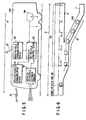
- FIG. 4 shows an arrangement of an on-road system for achieving vehicle-to-vehicle control with the use of the present system.
- the vehicle-to-vehicle control is done under which, with a vehicle-to-vehicle sensor 80 such as a radar mounted on the vehicle 100, the vehicle 100 can run in a way to be kept at a predetermined distance (vehicle-to-vehicle distance) relative to a preceding vehicle on the basis of the vehicle-to-vehicle distance detected by the sensor 80 and a group of vehicles can run as one unit in a way to be kept at such a predetermined distance.
- a predetermined distance vehicle-to-vehicle distance
- the vehicle-to-vehicle control is accomplished both with the use of the vehicle-to-vehicle distance detected by the sensor 80 and through the utilization of a communication (hereinafter referred to as a vehicle/vehicle communication) 91 between the vehicle and the adjacent vehicle or a communication (hereinafter referred to as a road/vehicle communication) 92 made on data items (data items on the position and speed of the running vehicle) from the position information equipment 3 via the communication equipment 4.
- a communication hereinafter referred to as a vehicle/vehicle communication
- a communication hereinafter referred to as a road/vehicle communication
- FIG. 5 shows an arrangement of an on-vehicle system for realizing the vehicle-to-vehicle control.
- the vehicle 100 has the vehicle-to-vehicle sensor 80 so as to detect the vehicle distance relative to the preceding vehicle and includes vehicle/vehicle communication device 81 for conducting the vehicle/vehicle communication 91, a road/vehicle communication device 82 for conducting a communication (road/vehicle communication) 92 between itself and the running control computer 5 via the communication equipment 4, and a vehicle-to-vehicle device 82.
- the vehicle-to-vehicle control device 83 is connected to the vehicle-to-vehicle detection sensor 80, vehicle-to-vehicle communication device 81 and road/vehicle communication device 82. And data items are passed between a drive device 84 and these associated devices.
- an MT (MT on the main line) 2 is generated by the running control computer 6 on the main road (imaginary running line equivalent to the main road set on the running control computer in FIG. 3) 2 at a predetermined interval and moving speed.
- the running control computer 5 allocates the MT2 to the approaching vehicle.
- An MT2 not imparted to the vehicle moves as a null MT2 on the main road 6.
- the running control computer 5 allocates an MT (joining MT) 1 to only a head vehicle in the group of vehicles (joining vehicle group).
- the running control computer 5 calculates a length of the joining vehicle group, 10, as follows:
- the running control computer 5 handles the head MT2 of the MT group 40 as an MT on the main road.
- the running control computer 5 allows the joining MT1 which is allocated to the head vehicle of the joining vehicle group 10 to synchronize with, and follow, a corresponding MT21.
- the respective vehicle in the joining vehicle group 10 is vehicle-to-vehicle controlled. Therefore, in spite of the joining MT1 being not allocated to other than the head vehicle of the joining vehicle group 10, it is possible to effect stable joining of the subsequent vehicle in the vehicle group.
- the running vehicle group controlling method if the above-mentioned condition is not met, that is, if the length of the null MT group is shorter than that of the joining vehicle group, a wait is required until a null MT group satisfying the length of the joining vehicle group arrives. This leads to a time loss.
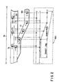
- the running control computer 5 in FIG. 3 finds the lengths of null MT groups 40A, 40B, ⁇ , that is, continuous null Mt2 groups divided by a corresponding vehicle (on the main road) as shown in FIG. 7. Further, the running control computer 5 divides the joining vehicle group 10 which approaches to the branch road 7 into a plurality of joining vehicle groups so as to make the length of the joining vehicle group shorter than that of the found null MT group. That is, the joining vehicle groups are reorganized.
- the lengths MTA, MTB, MTC ⁇ of the null MT groups 40A, 40B, 40C, ⁇ are found and that the joining vehicle group 10 is divided into joining vehicle groups 10A, 10B, 10C ⁇ .
- the running control computer 5 allocates a joining MT1 to only a head vehicle in the respective joining vehicle groups 10A, 10B, 10C ⁇ .
- the running control computer 5 handles a head MT2 of the null MT group 40A as a corresponding MT21 on the main road and sets the joining MT1 of the joining vehicle group 10A in synchronism with a corresponding MT21 on the main road, so that vehicle joining is achieved.
- the running control computer 5 handles a head MT2 of a subsequent null MT group 40B as a corresponding MT21 on the main road and sets joining MT1 of the joining vehicle group 10B in synchronism with the corresponding MT21 to achieve vehicle joining.
- safe joining is achieved for all joining vehicle groups divided.
- a joining MT is allocated only to the head vehicle and a head MT of a continuous null MT group greater in length than the joining vehicle group is handled as a corresponding MT on the main road and the joining MT is set in synchronism with the corresponding MT.
- the length of a joining vehicle group is so divided as to be matched to that of the null MT group and, by doing so, the joining vehicle group is reorganized. It is, therefore, possible to achieve still higher-efficient vehicle joining without allocating a joining MT to every vehicle, disturbing the vehicle-to-vehicle control among the vehicle groups and involving any loss time for waiting for a null MT group greater in length than a joining vehicle group.
Landscapes
- Physics & Mathematics (AREA)
- General Physics & Mathematics (AREA)
- Life Sciences & Earth Sciences (AREA)
- Atmospheric Sciences (AREA)
- Traffic Control Systems (AREA)
- Control Of Driving Devices And Active Controlling Of Vehicle (AREA)
Claims (6)
- Procédé de commande d'un groupe de véhicules en déplacement pour commander de façon automatique une pluralité de véhicules (100) en déplacement sur une route de circulation, caractérisé en ce qu'il comprend les étapes consistant à :lorsqu'un groupe de véhicules commandé en tant qu'unité sous commande véhicule à véhicule pour maintenir une distance véhicule à véhicule constante approche d'un carrefour et rejoint une route principale, affecter une cible mobile d'insertion à seulement un véhicule de tête dans un groupe de véhicules s'insérant (10), et, lorsqu'une longueur d'un groupe cible mobile vide et continu (40) sur la route principale est plus longue que celle du groupe de véhicules s'insérant (10), établir une cible mobile de tête (21) du groupe cible mobile vide (40) en synchronisme avec la cible mobile (1) d'insertion et se faisant, effectuer l'insertion de véhicule.
- Procédé selon la revendication 1, caractérisé en ce que, lorsque la longueur du groupe cible mobile vide (40) est inférieure à celle du groupe de véhicules s'insérant (10), le groupe de véhicules s'insérant (10) est divisé en groupes (10A, 10B) de façon à rendre la longueur du groupe de véhicules s'insérant (10) inférieure à celle du groupe cible mobile vide (40) et établir la cible mobile de tête du groupe cible mobile vide (40), comme une cible mobile (21) sur le côté de la route principale, en synchronisme avec la cible mobile (1) d'insertion et se faisant, effectuer l'insertion de véhicule.
- Système de commande d'un groupe de véhicules en déplacement pour commander de façon automatique une pluralité de véhicules en déplacement sur une route de circulation, caractérisé en ce qu'il comprend un système de route (3, 4, 5) installé sur la route de circulation et adapté pour commander le déplacement d'une pluralité de véhicules sur la route de façon à suivre une cible mobile se déplaçant sur une route de circulation imaginaire correspondant à la route de circulation et un système embarqué (80, 81 ,82 ,83) installé dans les véhicules (100) et adapté pour effectuer une commande véhicule à véhicule de la pluralité de véhicules se déplaçant sur la route de circulation, le système de route (3, 4, 5) et le système embarqué (80, 81, 82, 83) comprenant :des moyens pour, lorsqu'un groupe de véhicules commandé en tant qu'unité sous commande véhicule à véhicule pour maintenir une distance véhicule à véhicule constante approche d'un carrefour et rejoint une route principale, affecter une cible mobile (1) d'insertion à seulement un véhicule de tête d'un groupe de véhicules s'insérant (10) ; etdes moyens pour, lorsqu'une longueur d'un groupe cible mobile vide en continu (40) sur la route principale est plus grande que celle du groupe de véhicules s'insérant (10), établir une cible mobile de tête (21) du groupe cible en déplacement vide (40), comme la cible mobile (21) sur la route principale, en synchronisme avec la cible mobile (1) d'insertion et se faisant, effectuer l'insertion de véhicule.
- Système selon la revendication 3, caractérisé en ce que le système sur route (3, 4, 5) et le système embarqué (80, 81, 82, 83) comprennent en outre :des moyens pour, lorsqu'une longueur du groupe cible mobile vide (40) est inférieure à celle du groupe de véhicules s'insérant (10), diviser le groupe de véhicules s'insérant (10) en groupes de véhicules s'insérant (10A, 10B) de façon à rendre la longueur du groupe de véhicules s'insérant (10) inférieure à celle du groupe cible mobile vide (40),des moyens pour affecter une cible mobile (1) d'insertion aux véhicules de tête des groupes de véhicules s'insérant (10A, 10B), etdes moyens pour établir la cible mobile de tête du groupe cible mobile vide (40), comme une cible mobile (21) sur la route principale, en synchronisme avec la cible mobile (1) d'insertion et se faisant, effectuer l'insertion de véhicule.
- Système selon la revendication 3, caractérisé en ce que le système de route (3, 4, 5) comprend :un groupe d'équipement d'information de position (3) pour détecter une position et une vitesse des véhicules en déplacement;un ordinateur de commande de déplacement (5) pour effectuer une gestion et une commande des véhicules en déplacement en fonction des informations de position de véhicules détectées par le groupe d'équipement d'information de position (3) ; etun équipement de communication (4) pour permettre l'établissement de communications en fournissant les informations aux véhicules en déplacememnt à partir de l'ordinateur (5), transmettre une instruction de commande et obtenir une information à partir du véhicule en déplacement.
- Système selon la revendication 3, caractérisé en ce que le système embarqué (80, 81, 82, 820) comprend :un capteur de détection véhicule à véhicule (80) pour détecter une distance véhicule à véhicule relative à un véhicule précédent ;un dispositif de communication véhicule/véhicule (81) pour établir des communications véhicule/véhicule;un dispositif de communication route/véhicule (82) pour établir des communications route/véhicule entre le véhicule et l'ordinateur de commande de déplcament (5) par l'intermédiaire de l'équipement de communication (82) ; etun dispositif de commande véhicule à véhicule (83) relié au capteur véhicule à véhicule (80), au dispositif de communication véhicule/véhicule (81), au dispositif de communication route/véhicule (82) et au dispositif d'entraínement de véhicule (84) et adapté pour effectuer une commande véhicule à véhicule relativement à un véhicule précédent.
Applications Claiming Priority (3)
| Application Number | Priority Date | Filing Date | Title |
|---|---|---|---|
| JP225099/97 | 1997-08-21 | ||
| JP22509997 | 1997-08-21 | ||
| JP22509997A JP3268239B2 (ja) | 1997-08-21 | 1997-08-21 | 走行車両群制御方法 |
Publications (3)
| Publication Number | Publication Date |
|---|---|
| EP0898258A2 EP0898258A2 (fr) | 1999-02-24 |
| EP0898258A3 EP0898258A3 (fr) | 2000-06-14 |
| EP0898258B1 true EP0898258B1 (fr) | 2003-11-12 |
Family
ID=16823977
Family Applications (1)
| Application Number | Title | Priority Date | Filing Date |
|---|---|---|---|
| EP98114775A Expired - Lifetime EP0898258B1 (fr) | 1997-08-21 | 1998-08-06 | Procédé et système de contrôle d'une pluralité de véhicules en tant qu'une unité de groupe |
Country Status (4)
| Country | Link |
|---|---|
| US (1) | US6167331A (fr) |
| EP (1) | EP0898258B1 (fr) |
| JP (1) | JP3268239B2 (fr) |
| DE (1) | DE69819629T2 (fr) |
Families Citing this family (19)
| Publication number | Priority date | Publication date | Assignee | Title |
|---|---|---|---|---|
| JP3174833B2 (ja) * | 1999-10-27 | 2001-06-11 | 建設省土木研究所長 | 右折衝突防止システム |
| JP3478386B2 (ja) * | 2000-05-26 | 2003-12-15 | 村田機械株式会社 | 搬送車システム |
| US6725152B2 (en) * | 2002-02-21 | 2004-04-20 | Lockheed Martin Corporation | Real-time route and sensor planning system with variable mission objectives |
| US7647232B2 (en) | 2002-02-21 | 2010-01-12 | Lockheed Martin Corporation | Real-time team coordination system for reconnaissance and surveillance missions |
| US6687606B1 (en) | 2002-02-21 | 2004-02-03 | Lockheed Martin Corporation | Architecture for automatic evaluation of team reconnaissance and surveillance plans |
| US6718261B2 (en) | 2002-02-21 | 2004-04-06 | Lockheed Martin Corporation | Architecture for real-time maintenance of distributed mission plans |
| US7860639B2 (en) * | 2003-02-27 | 2010-12-28 | Shaoping Yang | Road traffic control method and traffic facilities |
| JP3928571B2 (ja) * | 2003-03-14 | 2007-06-13 | トヨタ自動車株式会社 | 車両用運転補助装置 |
| AU2004294651A1 (en) * | 2003-10-21 | 2005-06-16 | Proxy Aviation Systems, Inc. | Methods and apparatus for unmanned vehicle control |
| ATE368916T1 (de) * | 2005-01-14 | 2007-08-15 | Alcatel Lucent | Navigationsdienst |
| US8060283B2 (en) * | 2007-10-15 | 2011-11-15 | Deere & Company | Method and system for controlling the loading of a container associated with a vehicle |
| JP4670932B2 (ja) * | 2008-09-30 | 2011-04-13 | 沖電気工業株式会社 | 車々間無線通信装置及び車々間通信方法 |
| CN102292753B (zh) * | 2009-01-23 | 2014-10-15 | 丰田自动车株式会社 | 车组控制方法及车辆 |
| US8730059B2 (en) * | 2009-11-24 | 2014-05-20 | International Business Machines Corporation | Optimizing traffic speeds to minimize traffic pulses in an intelligent traffic system |
| JP5668741B2 (ja) * | 2012-10-04 | 2015-02-12 | 株式会社デンソー | 隊列走行装置 |
| JP5737316B2 (ja) * | 2013-04-17 | 2015-06-17 | 株式会社デンソー | 隊列走行システム |
| JP2016007954A (ja) * | 2014-06-25 | 2016-01-18 | トヨタ自動車株式会社 | 車線合流支援装置 |
| US20170213461A1 (en) * | 2016-01-21 | 2017-07-27 | Ford Global Technologies, Llc | System and method for vehicle group communication via dedicated short range communication |
| CN111243296B (zh) * | 2020-01-15 | 2020-11-27 | 清华大学 | 一种基于合流时间优化的匝道合流协同控制方法及系统 |
Family Cites Families (13)
| Publication number | Priority date | Publication date | Assignee | Title |
|---|---|---|---|---|
| US5297049A (en) * | 1982-11-08 | 1994-03-22 | Hailemichael Gurmu | Vehicle guidance system |
| US5179329A (en) * | 1989-04-25 | 1993-01-12 | Shinko Electric Co., Ltd. | Travel control method, travel control device, and mobile robot for mobile robot systems |
| CA2053028C (fr) * | 1990-10-23 | 1996-04-09 | Hideichi Tanizawa | Systeme de controle de la circulation de chariots |
| US5331561A (en) * | 1992-04-23 | 1994-07-19 | Alliant Techsystems Inc. | Active cross path position correlation device |
| US5369591A (en) * | 1993-03-11 | 1994-11-29 | Broxmeyer; Charles | Vehicle longitudinal control and collision avoidance system for an automated highway system |
| IL108549A (en) * | 1994-02-03 | 1998-08-16 | Zelinkovsky Reuven | Transport system |
| JPH08106596A (ja) * | 1994-10-06 | 1996-04-23 | Nippon Signal Co Ltd:The | 交通信号制御方法 |
| ATE175514T1 (de) * | 1994-11-28 | 1999-01-15 | Mannesmann Ag | Verfahren zur reduzierung einer aus den fahrzeugen einer stichprobenfahrzeugflotte zu übertragenden datenmenge |
| JPH08263793A (ja) * | 1995-03-23 | 1996-10-11 | Honda Motor Co Ltd | 車両制御装置 |
| JP3087606B2 (ja) * | 1995-05-11 | 2000-09-11 | 株式会社日立製作所 | 自動車用車間距離計測装置及び方法 |
| JP3633707B2 (ja) * | 1996-03-08 | 2005-03-30 | 日産ディーゼル工業株式会社 | 車群走行制御装置 |
| DE19637245C2 (de) * | 1996-09-13 | 2000-02-24 | Bosch Gmbh Robert | Verfahren und Vorrichtung zur Regelung der Geschwindigkeit eines Fahrzeugs |
| US5936517A (en) * | 1998-07-03 | 1999-08-10 | Yeh; Show-Way | System to minimize the distance between trains |
-
1997
- 1997-08-21 JP JP22509997A patent/JP3268239B2/ja not_active Expired - Fee Related
-
1998
- 1998-08-06 EP EP98114775A patent/EP0898258B1/fr not_active Expired - Lifetime
- 1998-08-06 DE DE69819629T patent/DE69819629T2/de not_active Expired - Lifetime
- 1998-08-19 US US09/136,402 patent/US6167331A/en not_active Expired - Fee Related
Also Published As
| Publication number | Publication date |
|---|---|
| EP0898258A3 (fr) | 2000-06-14 |
| JP3268239B2 (ja) | 2002-03-25 |
| DE69819629T2 (de) | 2004-09-16 |
| EP0898258A2 (fr) | 1999-02-24 |
| US6167331A (en) | 2000-12-26 |
| DE69819629D1 (de) | 2003-12-18 |
| JPH1166498A (ja) | 1999-03-09 |
Similar Documents
| Publication | Publication Date | Title |
|---|---|---|
| EP0898258B1 (fr) | Procédé et système de contrôle d'une pluralité de véhicules en tant qu'une unité de groupe | |
| EP0898257B1 (fr) | Méthode de commande de véhicule en marche | |
| KR102338731B1 (ko) | 열차 제어 시스템 | |
| CN1137993A (zh) | 在列车之间建立相互联系的方法及实施该方法的装置 | |
| KR960007039B1 (ko) | 운송네트워크와 그러한 네트워크를 통한 차량이동의 제어방법 | |
| EP0867352B1 (fr) | Procede de commande automatique de la circulation d'un vehicule | |
| CN112526990B (zh) | 机器人通过窄道的方法、装置、可读存储介质及机器人 | |
| EP1850151A3 (fr) | Système de contrôle de la position des flûtes sismiques marines | |
| EP0911778A3 (fr) | Système de contrôle de la circulation pour véhicule | |
| EP1754644A1 (fr) | Système de contrôle d"exploitation de train | |
| AUPP965299A0 (en) | Air traffic management system | |
| IL107619A (en) | Real time passive threat positioning system | |
| US12039871B2 (en) | Method for operating a transportation system | |
| KR100283828B1 (ko) | 열차 운행관리 시스템 | |
| US20220292985A1 (en) | Method for opearting a transportation system | |
| CN108303987A (zh) | 一种电动汽车的自动驾驶控制系统及方法 | |
| US20220292983A1 (en) | Method for autonomous control of vehicles of a transportation system | |
| US20220292984A1 (en) | Method for operating a transportation system | |
| Bianco et al. | Dynamic algorithms for TMA traffic management | |
| CN119125296A (zh) | 基于智能涂装系统的飞机损伤检测方法、装置及设备 | |
| FR2693059B1 (fr) | Procédé de transmission de signaux électriques par voie hertzienne, et système, de transmission pour la mise en Óoeuvre de ce procédé. | |
| CN120748181A (zh) | 一种基于云控平台的车辆预测巡航控制系统、方法及装置 | |
| JP3392723B2 (ja) | 自動運転合流における走行車両制御方法 | |
| JP2000293783A (ja) | 車両走行システムおよび車両自動走行方法 | |
| JPH10186013A (ja) | 情報処理装置 |
Legal Events
| Date | Code | Title | Description |
|---|---|---|---|
| PUAI | Public reference made under article 153(3) epc to a published international application that has entered the european phase |
Free format text: ORIGINAL CODE: 0009012 |
|
| 17P | Request for examination filed |
Effective date: 19980806 |
|
| AK | Designated contracting states |
Kind code of ref document: A2 Designated state(s): DE FR GB IT |
|
| AX | Request for extension of the european patent |
Free format text: AL;LT;LV;MK;RO;SI |
|
| PUAL | Search report despatched |
Free format text: ORIGINAL CODE: 0009013 |
|
| AK | Designated contracting states |
Kind code of ref document: A3 Designated state(s): AT BE CH CY DE DK ES FI FR GB GR IE IT LI LU MC NL PT SE |
|
| AX | Request for extension of the european patent |
Free format text: AL;LT;LV;MK;RO;SI |
|
| RIC1 | Information provided on ipc code assigned before grant |
Free format text: 7G 08G 1/09 A, 7G 08G 1/07 B, 7G 08G 1/16 B |
|
| AKX | Designation fees paid |
Free format text: DE FR GB IT |
|
| GRAH | Despatch of communication of intention to grant a patent |
Free format text: ORIGINAL CODE: EPIDOS IGRA |
|
| GRAS | Grant fee paid |
Free format text: ORIGINAL CODE: EPIDOSNIGR3 |
|
| GRAA | (expected) grant |
Free format text: ORIGINAL CODE: 0009210 |
|
| AK | Designated contracting states |
Kind code of ref document: B1 Designated state(s): DE FR GB IT |
|
| REG | Reference to a national code |
Ref country code: GB Ref legal event code: FG4D |
|
| REF | Corresponds to: |
Ref document number: 69819629 Country of ref document: DE Date of ref document: 20031218 Kind code of ref document: P |
|
| ET | Fr: translation filed | ||
| REG | Reference to a national code |
Ref country code: GB Ref legal event code: 746 Effective date: 20040615 |
|
| REG | Reference to a national code |
Ref country code: FR Ref legal event code: D6 |
|
| PLBE | No opposition filed within time limit |
Free format text: ORIGINAL CODE: 0009261 |
|
| STAA | Information on the status of an ep patent application or granted ep patent |
Free format text: STATUS: NO OPPOSITION FILED WITHIN TIME LIMIT |
|
| 26N | No opposition filed |
Effective date: 20040813 |
|
| PGFP | Annual fee paid to national office [announced via postgrant information from national office to epo] |
Ref country code: IT Payment date: 20100814 Year of fee payment: 13 |
|
| PGFP | Annual fee paid to national office [announced via postgrant information from national office to epo] |
Ref country code: DE Payment date: 20110803 Year of fee payment: 14 Ref country code: FR Payment date: 20110818 Year of fee payment: 14 Ref country code: GB Payment date: 20110803 Year of fee payment: 14 |
|
| GBPC | Gb: european patent ceased through non-payment of renewal fee |
Effective date: 20120806 |
|
| REG | Reference to a national code |
Ref country code: FR Ref legal event code: ST Effective date: 20130430 |
|
| PG25 | Lapsed in a contracting state [announced via postgrant information from national office to epo] |
Ref country code: IT Free format text: LAPSE BECAUSE OF NON-PAYMENT OF DUE FEES Effective date: 20120806 |
|
| PG25 | Lapsed in a contracting state [announced via postgrant information from national office to epo] |
Ref country code: DE Free format text: LAPSE BECAUSE OF NON-PAYMENT OF DUE FEES Effective date: 20130301 Ref country code: GB Free format text: LAPSE BECAUSE OF NON-PAYMENT OF DUE FEES Effective date: 20120806 |
|
| PG25 | Lapsed in a contracting state [announced via postgrant information from national office to epo] |
Ref country code: FR Free format text: LAPSE BECAUSE OF NON-PAYMENT OF DUE FEES Effective date: 20120831 |
|
| REG | Reference to a national code |
Ref country code: DE Ref legal event code: R119 Ref document number: 69819629 Country of ref document: DE Effective date: 20130301 |