EP0899443A2 - Procédé et dispositif d'injection de carburant d'un moteur à combustion - Google Patents
Procédé et dispositif d'injection de carburant d'un moteur à combustion Download PDFInfo
- Publication number
- EP0899443A2 EP0899443A2 EP98306779A EP98306779A EP0899443A2 EP 0899443 A2 EP0899443 A2 EP 0899443A2 EP 98306779 A EP98306779 A EP 98306779A EP 98306779 A EP98306779 A EP 98306779A EP 0899443 A2 EP0899443 A2 EP 0899443A2
- Authority
- EP
- European Patent Office
- Prior art keywords
- fuel injection
- fuel
- pressure
- common rail
- injection amount
- Prior art date
- Legal status (The legal status is an assumption and is not a legal conclusion. Google has not performed a legal analysis and makes no representation as to the accuracy of the status listed.)
- Granted
Links
- 239000000446 fuel Substances 0.000 title claims abstract description 249
- 238000002347 injection Methods 0.000 title claims abstract description 179
- 239000007924 injection Substances 0.000 title claims abstract description 179
- 238000000034 method Methods 0.000 title claims abstract description 12
- 238000002485 combustion reaction Methods 0.000 claims description 11
- 238000001514 detection method Methods 0.000 claims description 6
- 230000003111 delayed effect Effects 0.000 claims description 3
- 230000001934 delay Effects 0.000 claims description 2
- 230000009467 reduction Effects 0.000 abstract description 9
- 230000000994 depressogenic effect Effects 0.000 abstract description 2
- 230000007423 decrease Effects 0.000 description 7
- 239000002828 fuel tank Substances 0.000 description 4
- 230000001276 controlling effect Effects 0.000 description 3
- 230000003247 decreasing effect Effects 0.000 description 2
- 238000006073 displacement reaction Methods 0.000 description 2
- 230000001105 regulatory effect Effects 0.000 description 2
- 230000015556 catabolic process Effects 0.000 description 1
- 239000000498 cooling water Substances 0.000 description 1
- 238000006731 degradation reaction Methods 0.000 description 1
- 230000000593 degrading effect Effects 0.000 description 1
- 230000006866 deterioration Effects 0.000 description 1
- 230000002542 deteriorative effect Effects 0.000 description 1
- 238000010586 diagram Methods 0.000 description 1
- 230000001737 promoting effect Effects 0.000 description 1
- 230000001052 transient effect Effects 0.000 description 1
- XLYOFNOQVPJJNP-UHFFFAOYSA-N water Substances O XLYOFNOQVPJJNP-UHFFFAOYSA-N 0.000 description 1
Images


Classifications
-
- F—MECHANICAL ENGINEERING; LIGHTING; HEATING; WEAPONS; BLASTING
- F02—COMBUSTION ENGINES; HOT-GAS OR COMBUSTION-PRODUCT ENGINE PLANTS
- F02D—CONTROLLING COMBUSTION ENGINES
- F02D41/00—Electrical control of supply of combustible mixture or its constituents
- F02D41/30—Controlling fuel injection
- F02D41/38—Controlling fuel injection of the high pressure type
- F02D41/3809—Common rail control systems
- F02D41/3836—Controlling the fuel pressure
- F02D41/3845—Controlling the fuel pressure by controlling the flow into the common rail, e.g. the amount of fuel pumped
-
- F—MECHANICAL ENGINEERING; LIGHTING; HEATING; WEAPONS; BLASTING
- F02—COMBUSTION ENGINES; HOT-GAS OR COMBUSTION-PRODUCT ENGINE PLANTS
- F02D—CONTROLLING COMBUSTION ENGINES
- F02D41/00—Electrical control of supply of combustible mixture or its constituents
- F02D41/02—Circuit arrangements for generating control signals
- F02D41/04—Introducing corrections for particular operating conditions
- F02D41/12—Introducing corrections for particular operating conditions for deceleration
-
- F—MECHANICAL ENGINEERING; LIGHTING; HEATING; WEAPONS; BLASTING
- F02—COMBUSTION ENGINES; HOT-GAS OR COMBUSTION-PRODUCT ENGINE PLANTS
- F02D—CONTROLLING COMBUSTION ENGINES
- F02D41/00—Electrical control of supply of combustible mixture or its constituents
- F02D41/30—Controlling fuel injection
- F02D41/38—Controlling fuel injection of the high pressure type
- F02D41/40—Controlling fuel injection of the high pressure type with means for controlling injection timing or duration
-
- F—MECHANICAL ENGINEERING; LIGHTING; HEATING; WEAPONS; BLASTING
- F02—COMBUSTION ENGINES; HOT-GAS OR COMBUSTION-PRODUCT ENGINE PLANTS
- F02D—CONTROLLING COMBUSTION ENGINES
- F02D2250/00—Engine control related to specific problems or objectives
- F02D2250/31—Control of the fuel pressure
-
- F—MECHANICAL ENGINEERING; LIGHTING; HEATING; WEAPONS; BLASTING
- F02—COMBUSTION ENGINES; HOT-GAS OR COMBUSTION-PRODUCT ENGINE PLANTS
- F02D—CONTROLLING COMBUSTION ENGINES
- F02D41/00—Electrical control of supply of combustible mixture or its constituents
- F02D41/30—Controlling fuel injection
- F02D41/38—Controlling fuel injection of the high pressure type
- F02D41/3809—Common rail control systems
- F02D41/3836—Controlling the fuel pressure
- F02D41/3863—Controlling the fuel pressure by controlling the flow out of the common rail, e.g. using pressure relief valves
- F02D41/3872—Controlling the fuel pressure by controlling the flow out of the common rail, e.g. using pressure relief valves characterised by leakage flow in injectors
-
- Y—GENERAL TAGGING OF NEW TECHNOLOGICAL DEVELOPMENTS; GENERAL TAGGING OF CROSS-SECTIONAL TECHNOLOGIES SPANNING OVER SEVERAL SECTIONS OF THE IPC; TECHNICAL SUBJECTS COVERED BY FORMER USPC CROSS-REFERENCE ART COLLECTIONS [XRACs] AND DIGESTS
- Y02—TECHNOLOGIES OR APPLICATIONS FOR MITIGATION OR ADAPTATION AGAINST CLIMATE CHANGE
- Y02T—CLIMATE CHANGE MITIGATION TECHNOLOGIES RELATED TO TRANSPORTATION
- Y02T10/00—Road transport of goods or passengers
- Y02T10/10—Internal combustion engine [ICE] based vehicles
- Y02T10/40—Engine management systems
Definitions
- the present invention relates to a method and device for controlling a common rail pressure in a common-rail type fuel injection system.
- a common-rail type fuel injection system which provides a high injection pressure and performs optimum control on injection characteristics, such as fuel injection timing and the amount of fuel injected, according to the operating condition of the engine.
- the common rail type fuel injection system is a fuel injection system that stores in the common rail a fuel pressurized to a predetermined pressure by a pump and then injects the stored fuel from injectors into corresponding combustion chambers.
- a controller controls the fuel pressure in the common rail and the operation of control valves for the injectors according to the operating conditions of the engine.
- the conventional common-rail type fuel injection system will be described by referring to Figure 5.
- the fuel is supplied to individual injectors 1 from a common rail 2 through branch pipes 3 that form a part of the fuel passage.
- the fuel which was pumped by a feed pump 6 from a fuel tank 4 through a filter 5 and pressurized to a predetermined pressure, is delivered to a fuel pump 8 through a fuel pipe 7.
- the fuel pump 8 may, for example, be a so-called plunger type fuel supply pump driven by the engine which raises the fuel pressure to a high pressure determined by the operating condition of the engine and delivers the pressurized fuel through a fuel pipe 9 to the common rail 2.
- the fuel is then stored temporarily in the common rail 2 at the elevated pressure, from which it is supplied to individual injectors 1.
- injectors 1 Normally there are provided two or more injectors 1 corresponding in number to cylinders in the engine (or according to the type of engine). These injectors 1 are controlled by a controller 12 to inject fuel supplied from the common rail 2 into the corresponding combustion chambers in optimum amounts and at optimum timings. Because the pressure at which the fuel is injected from the injectors 1 is equal to the pressure of the fuel stored in the common rail 2, the injection pressure is controlled by controlling the fuel pressure in the common rail 2.
- the fuel released from the fuel pump 8 is returned to the fuel tank 4 through a return pipe 10.
- the fuel that was not used for injection into the combustion chambers is returned to the fuel tank 4 through a return pipe 11.
- the controller 12 as an electronic control unit is supplied with signals from various sensors for detecting the engine operating condition, which include: engine cylinder determination and crank angle sensors for detecting an engine revolution speed Ne; an accelerator opening sensor for detecting the amount of accelerator operation Acc; a water temperature sensor for detecting the cooling water temperature; and an intake pipe inner pressure sensor for detecting the inner pressure of the intake pipe.
- the controller 12 controls the fuel injection characteristics of the injectors 1, i.e., the fuel injection timing and the amount of fuel to be injected so that the engine output will become optimum for the current engine operating condition.
- the common rail 2 is provided with a pressure sensor 13 which detects the fuel pressure in the common rail 2 and sends the detection signal to the controller 12.
- the controller 12 controls the delivery pressure of the fuel pump 8 so that the fuel pressure in the common rail 2 remains constant even when the fuel in the common rail 2 is consumed for the injection from the injectors 1.
- the common-rail type fuel injection device controls the injection pressure to a target value according to the operating condition and at the same time calculates injection characteristics corresponding to the operating condition, i.e., the amount of fuel to be injected (determined by the fuel injection pressure and the fuel injection timing), and, according to the calculated results, controls the valve openings of the injectors for injecting high-pressure fuel, thereby realizing the fuel injection characteristics conforming to the engine operating state.
- the fuel pressure is raised by a pump and regulated by a pressure regulating valve to a predetermined injection pressure.
- the common rail target pressure under normal (steady state) operating condition is so set that the exhaust emission performance is optimum. Under a transient state where the common rail target pressure is not constant, however, the exhaust emission performance may deteriorate unless an appropriate pressure control is provided. That is, in the common-rail type fuel injection device, although raising the fuel injection pressure can easily be done by raising the common rail pressure by operating the control valve of the fuel pump, the common rail pressure cannot be lowered except by fuel injection from the injectors or by leaking fuel from the injection system such as common rail.
- the engine output revolution decreases and the common rail target pressure determined by the controller according to the result of detection of the amount of the accelerator pedal depression quickly becomes small.
- the actual common rail pressure cannot follow the rapid reduction in the target pressure and remains high. That is, because the fuel injection from the injectors are stopped, the fuel in the common rail is not consumed. Further, the fuel cannot be expected to leak within a short period of time from an injection system ranging from the common rail to the injectors. Hence, the actual common rail pressure continues to be high. In such a condition, when the fuel injection from the injectors is resumed, the fuel is injected at high pressure, increasing NOx and degrading the exhaust emission performance.
- Japanese Patent Laid-Open No. 117147/1988 discloses a fuel injection device incorporating a rapid pressure reducing system in the common rail.
- the rapid pressure reducing system is a fuel injection control device for internal combustion engines that delivers fuel by a variable displacement pump from the fuel tank to a fuel accumulator, supplies fuel from the fuel accumulator to the fuel injection valves, and controls the amount of fuel delivered by the variable displacement fuel pump so that the fuel pressure in the fuel accumulator detected by a pressure sensor matches the target fuel pressure determined according to the engine operating condition.
- a pressure reduction relief valve (solenoid valve) provided in the fuel accumulator is opened to release the high pressure fuel from the fuel accumulator through a relief pipe.
- the aim of this invention is to solve the above problem by using the existing system without having to use additional parts such as relief valve and relief pipe and to provide a fuel injection method and device for engines which, when the fuel injection amount quickly decreases as when rapidly reducing the accelerator pedal depression amount to zero, enables a quick reduction in the common rail pressure by slightly increasing the fuel injection amount to such an extent as will not affect the engine output and the exhaust emission performance.
- the invention relates to a fuel injection method for engines which comprises the steps of: storing fuel delivered by a fuel pump in a common rail; determining a basic fuel injection amount and a target pressure of the common rail based on the engine operating condition; injecting the basic fuel injection amount of fuel supplied from the common rail into combustion chambers through injection holes formed in injectors; and controlling the fuel pump to match the pressure of the common rail with the target pressure of the common rail; wherein when a pressure condition is met in which the common rail pressure is higher than the target pressure by more than a predetermined value, the amount of fuel to be injected from the injectors is set to a second fuel injection amount which is smaller than a first fuel injection amount that stabilizes the engine revolution speed when the engine is running with no load.
- This invention also relates to a fuel injection device for engines which comprises: a common rail to store fuel delivered by a fuel pump; injectors formed with injection holes through which to inject the fuel supplied from the common rail into combustion chambers; an operation state detection means to detect an operating condition of the engine; a pressure sensor to detect a pressure of the common rail; and a controller to determine a basic fuel injection amount and a target pressure of the common rail based on the engine operating condition detected by the operation state detection means and to control the fuel pump to match the common rail pressure detected by the pressure sensor with the common rail target pressure; wherein when a pressure condition is met in which the common rail pressure is higher than the common rail target pressure by more than a predetermined value, the controller sets the amount of fuel to be injected from the injectors to a second fuel injection amount which is smaller than a first fuel injection amount that stabilizes the engine revolution speed when the engine is running with no load.
- the amount of fuel to be injected from the injectors is set to the second fuel injection amount which is less than the first fuel injection amount that stabilizes the engine revolution speed during the no-load operation. This ensures reduction in the engine revolution speed.
- the second fuel injection amount is equal to the first fuel injection amount (which may be constant or varies with the revolution speed) multiplied by a factor of less than one. Because the fuel corresponding to the second fuel injection amount continues to be supplied from the common rail to the injectors where it is consumed for injection, the common rail pressure can be reduced reliably.
- the accelerator is operated next to perform positive fuel injections, the fuel can be prevented from being injected at abnormally high common rail pressure or fuel injection pressure, thus avoiding degradation of the exhaust emission characteristics.
- the pressure condition is met and also the injection amount condition is met whereby the basic fuel injection amount is less than the second fuel injection amount
- the amount of fuel to be injected from the injectors is set to the second fuel injection amount.
- the basic fuel injection amount is very small, less than the second fuel injection amount
- the amount of fuel to be injected increases slightly to the second fuel injection amount. An increase in the amount of fuel supplied from the common rail therefore swiftly reduces the common rail pressure.
- the fuel injection timing at which to inject fuel from the injectors is delayed from an injection timing used when the pressure condition is not met. Because the common rail pressure when the pressure condition is met is higher than the target pressure by more than a predetermined value, the fuel is injected through injection holes of the injectors at higher injection pressures than when the pressure condition is not met. Therefore, a large amount of fuel can be injected even during a shorter injection period. Because injection of a large amount of fuel at an early stage in the fuel injection period can cause undesired phenomena in terms of engine characteristics such as knocking, the fuel injection timing is delayed.
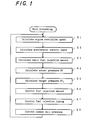
- Figure 1 is a flowchart of a main routine showing one example of a fuel injection control steps in the fuel injection method and device for engines of this invention.
- Figure 2 is a flowchart of a subroutine showing fuel injection amount control steps in the flowchart of figures 1.
- Figure 3 is a flowchart of a subroutine showing an injection timing control steps in the flowchart of Figure 1.
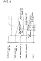
- Figure 4 is a graph showing how the engine revolution speed, the fuel injection amount and the common rail pressure change when the accelerator opening, i.e., the accelerator pedal depression amount, is reduced from a certain depression amount to zero.
- Figure 5 is a schematic diagram showing the common-rail type fuel injection system.
- Figure 4 shows how the engine revolution speed Ne, the fuel injection amount Q and the common rail pressure P change when the accelerator opening Acc, i.e., accelerator pedal depression amount, is changed from a certain depression amount to zero at time t 1 .
- the accelerator pedal depression is reduced from a certain depression amount to zero
- the basic fuel injection amount Qb represented by a solid line sharply decreases (for example, to zero) with the engine revolution speed Ne starting to slow down progressively.
- the basic fuel injection amount Qb i.e., the fuel supply from the common rail 2
- the actual pressure Pf of the common rail 2 can fall only slowly at a rate corresponding, for example, to the fuel leakage from the injectors 1.
- the target pressure Pf 0 of the common rail 2 as obtained from the predetermined map decreases with respect to the actual pressure Pf so that the exhaust emission performance at the next fuel injection timing will be appropriate.
- the target pressure Pf 0 calculated from the accelerator pedal depression amount Acc and the engine revolution speed Ne falls relatively fast but the actual pressure Pf cannot follow it.
- the difference (Pf - Pf 0 ) becomes larger than the predetermined value ⁇ and the basic fuel injection amount Qb is smaller than the second fuel injection amount equal to the first fuel injection amount Qpd multiplied by a certain factor k (0 ⁇ k ⁇ 1).
- the final fuel injection amount Qfin may be set to the basic fuel injection amount Qb.
- the second fuel injection amount Qpdxk is maintained. That is, as shown in Figure 4, the fuel injection amount control may be given a hysteresis in which when the correction increases the fuel injection amount, the control immediately increases it and in which when stopping the correction reduces the fuel injection amount, the control does not immediately reduces it but maintains the increased fuel injection amount for some time. This limits frequent variations in the fuel injection amount allowing a smooth control on the fuel injection amount.
- the target pressure Pf 0 rises after t 5 as shown by a two-dotted line. If the correction of the common rail pressure P is not made, the actual pressure Pf is still higher than the target pressure Pf 0 until time t 6 , causing deterioration of the exhaust emissions. But if the correction is made, it is seen that the actual pressure Pf is already reduced, improving the exhaust emissions.
Landscapes
- Engineering & Computer Science (AREA)
- Chemical & Material Sciences (AREA)
- Combustion & Propulsion (AREA)
- Mechanical Engineering (AREA)
- General Engineering & Computer Science (AREA)
- Electrical Control Of Air Or Fuel Supplied To Internal-Combustion Engine (AREA)
- Fuel-Injection Apparatus (AREA)
Applications Claiming Priority (3)
| Application Number | Priority Date | Filing Date | Title |
|---|---|---|---|
| JP24752497 | 1997-08-29 | ||
| JP24752497A JP3713918B2 (ja) | 1997-08-29 | 1997-08-29 | エンジンの燃料噴射方法及びその装置 |
| JP247524/97 | 1997-08-29 |
Publications (3)
| Publication Number | Publication Date |
|---|---|
| EP0899443A2 true EP0899443A2 (fr) | 1999-03-03 |
| EP0899443A3 EP0899443A3 (fr) | 2000-11-08 |
| EP0899443B1 EP0899443B1 (fr) | 2005-12-21 |
Family
ID=17164784
Family Applications (1)
| Application Number | Title | Priority Date | Filing Date |
|---|---|---|---|
| EP98306779A Expired - Lifetime EP0899443B1 (fr) | 1997-08-29 | 1998-08-25 | Procédé et dispositif d'injection de carburant d'un moteur à combustion |
Country Status (4)
| Country | Link |
|---|---|
| US (1) | US6105554A (fr) |
| EP (1) | EP0899443B1 (fr) |
| JP (1) | JP3713918B2 (fr) |
| DE (1) | DE69832858T2 (fr) |
Cited By (10)
| Publication number | Priority date | Publication date | Assignee | Title |
|---|---|---|---|---|
| WO2002006655A1 (fr) * | 2000-07-18 | 2002-01-24 | Robert Bosch Gmbh | Procede et dispositif pour commander un moteur a combustion interne |
| EP1273780A3 (fr) * | 2001-07-02 | 2005-01-05 | Robert Bosch Gmbh | Procédé de commande d'un moteur à combustion en particulier d'une automobile |
| EP1443197A3 (fr) * | 2003-01-31 | 2006-10-25 | Nissan Motor Company, Limited | Système de commande pour l'injection directe de carburant |
| DE102004055190B4 (de) * | 2004-05-12 | 2007-09-06 | Mitsubishi Denki K.K. | Kraftstoffeinspritz-Regelungsvorrichtung eines Verbrennungsmotors |
| KR100768358B1 (ko) * | 2000-07-18 | 2007-10-17 | 로베르트 보쉬 게엠베하 | 엔진 제어 방법 및 장치 |
| FR2976025A1 (fr) * | 2011-06-06 | 2012-12-07 | Peugeot Citroen Automobiles Sa | Procede de decharge de la pression dans une rampe commune d'un moteur thermique a injection directe |
| DE102004055193B4 (de) * | 2004-05-12 | 2014-01-16 | Mitsubishi Denki K.K. | Kraftstoffeinspritz-Regelungsvorrichtung eines Verbrennungsmotors |
| CN105593499A (zh) * | 2013-07-19 | 2016-05-18 | 康明斯公司 | 用于估算共轨燃料系统中的高压燃料泄露的系统和方法 |
| EP3184788A4 (fr) * | 2014-08-21 | 2017-09-13 | Nissan Motor Co., Ltd | Dispositif et procédé de commande d'injection de carburant pour moteur à combustion interne |
| EP3312407A4 (fr) * | 2015-06-19 | 2018-08-15 | Nissan Motor Co., Ltd. | Appareil de commande d'injection de carburant et procédé de commande d'un moteur à combustion interne |
Families Citing this family (25)
| Publication number | Priority date | Publication date | Assignee | Title |
|---|---|---|---|---|
| JP3695213B2 (ja) * | 1999-04-02 | 2005-09-14 | いすゞ自動車株式会社 | コモンレール式燃料噴射装置 |
| GB2366598A (en) * | 2000-09-07 | 2002-03-13 | Cummins Engine Co Ltd | Detecting leakage in the fuel rail of an i.c. engine |
| JP4627603B2 (ja) * | 2001-03-15 | 2011-02-09 | 日立オートモティブシステムズ株式会社 | 燃料供給装置 |
| JP3965098B2 (ja) * | 2002-09-30 | 2007-08-22 | ヤンマー株式会社 | コモンレール式燃料噴射装置の燃料圧力検出装置及びその燃料圧力検出装置を備えたコモンレール式燃料噴射装置 |
| JP2005127164A (ja) * | 2003-10-21 | 2005-05-19 | Denso Corp | コモンレール式燃料噴射装置 |
| JP4492467B2 (ja) * | 2005-07-13 | 2010-06-30 | 株式会社デンソー | 燃料噴射制御装置 |
| EP1790844A1 (fr) * | 2005-11-25 | 2007-05-30 | Delphi Technologies, Inc. | Méthode d'identification d'un comportement anormal d'un système dynamique |
| DE102006002738A1 (de) * | 2006-01-20 | 2007-08-02 | Robert Bosch Gmbh | Verfahren und Vorrichtung zur Steuerung einer Brennkraftmaschine |
| EP1870586B1 (fr) * | 2006-06-16 | 2018-12-05 | Delphi International Operations Luxembourg S.à r.l. | Appareil pour détecter et identifier les défaillances de composants dans un système de carburant |
| US7717088B2 (en) * | 2007-05-07 | 2010-05-18 | Ford Global Technologies, Llc | Method of detecting and compensating for injector variability with a direct injection system |
| EP2039920B1 (fr) * | 2007-09-21 | 2010-09-08 | Magneti Marelli S.p.A. | Procédé de contrôle pour système d'injection directe de type rail commun fourni avec robinet de sectionnement pour contrôler le débit d'une pompe à carburant haute pression |
| US7873460B2 (en) * | 2007-09-25 | 2011-01-18 | Denso Corporation | Controller for fuel injection system |
| EP2042720B1 (fr) * | 2007-09-26 | 2010-03-10 | Magneti Marelli S.p.A. | Procédé de commande pour un système d'injection directe à rampe d'alimentation commune comprenant une pompe à carburant à haute pression |
| DE102008035985B4 (de) * | 2008-08-01 | 2010-07-08 | Continental Automotive Gmbh | Verfahren und Vorrichtung zur Regelung des Kraftstoffdruckes im Druckspeicher eines Common-Rail-Einspritzsystems |
| US9371796B2 (en) * | 2011-01-07 | 2016-06-21 | Nissan Motor Co., Ltd. | Combustion control device and method for diesel engine |
| US9903306B2 (en) | 2013-02-08 | 2018-02-27 | Cummins Inc. | System and method for acquiring pressure data from a fuel accumulator of an internal combustion engine |
| US9551631B2 (en) | 2013-02-08 | 2017-01-24 | Cummins Inc. | System and method for adapting to a variable fuel delivery cutout delay in a fuel system of an internal combustion engine |
| US20140251275A1 (en) * | 2013-03-08 | 2014-09-11 | Cummins Inc. | Fuel injector fueling equalization system and method |
| DE102014007880B4 (de) * | 2014-05-24 | 2018-12-13 | Mtu Friedrichshafen Gmbh | Verfahren zur Einstellung des Drucks in einem Hochdrucksystem eines Kraftstoffeinspritzsystems einer Brennkraftmaschine und Brennkraftmaschine zur Durchführung des Verfahrens |
| US20160169133A1 (en) * | 2014-12-11 | 2016-06-16 | Caterpillar Inc. | System and method for increasing gaseous fuel substitution |
| GB2539013A (en) * | 2015-06-03 | 2016-12-07 | Gm Global Tech Operations Llc | Method of controlling a fuel injection system during rail pressure sensor failure condition |
| JP6380373B2 (ja) | 2015-12-25 | 2018-08-29 | トヨタ自動車株式会社 | 燃料圧力制御装置 |
| JP7054716B2 (ja) * | 2020-03-18 | 2022-04-14 | 本田技研工業株式会社 | 内燃機関の過給圧制御装置 |
| DE102021202000A1 (de) * | 2021-03-02 | 2022-09-08 | Hyundai Motor Company | Kraftstoffeinspritzsystem für einen verbrennungsmotor und verfahren sowie steuerungsvorrichtung zur steuerung eines kraftstoffeinspritzsystems eines verbrennungsmotors |
| EP4390104B1 (fr) * | 2022-12-20 | 2026-02-25 | Volvo Truck Corporation | Système et procédé de détermination de fuite d'injecteur de carburant |
Family Cites Families (13)
| Publication number | Priority date | Publication date | Assignee | Title |
|---|---|---|---|---|
| JPS6060020A (ja) * | 1983-09-09 | 1985-04-06 | Toyota Motor Corp | サスペンション用緩衝装置のばね特性制御装置 |
| US4841936A (en) * | 1985-06-27 | 1989-06-27 | Toyota Jidosha Kabushiki Kaisha | Fuel injection control device of an internal combustion engine |
| JPH0772511B2 (ja) * | 1986-11-01 | 1995-08-02 | トヨタ自動車株式会社 | 内燃機関の燃料噴射制御装置 |
| US5058553A (en) * | 1988-11-24 | 1991-10-22 | Nippondenso Co., Ltd. | Variable-discharge high pressure pump |
| JP2964665B2 (ja) * | 1991-02-27 | 1999-10-18 | 株式会社デンソー | ディーゼル機関の蓄圧式燃料噴射装置 |
| JP3173663B2 (ja) * | 1991-08-14 | 2001-06-04 | 本田技研工業株式会社 | 内燃エンジンの燃料噴射制御装置 |
| US5191867A (en) * | 1991-10-11 | 1993-03-09 | Caterpillar Inc. | Hydraulically-actuated electronically-controlled unit injector fuel system having variable control of actuating fluid pressure |
| US5678521A (en) * | 1993-05-06 | 1997-10-21 | Cummins Engine Company, Inc. | System and methods for electronic control of an accumulator fuel system |
| DE4445586A1 (de) * | 1994-12-20 | 1996-06-27 | Bosch Gmbh Robert | Verfahren zur Reduzierung des Kraftstoffdruckes in einer Kraftstoffeinspritzeinrichtung |
| JPH08338335A (ja) * | 1995-06-09 | 1996-12-24 | Nippondenso Co Ltd | 内燃機関の燃料供給装置 |
| EP0764777B1 (fr) * | 1995-09-23 | 2003-03-19 | Robert Bosch Gmbh | Méthode et appareil pour la commande d'un moteur à combustion interne |
| JP3453970B2 (ja) * | 1995-12-12 | 2003-10-06 | 株式会社デンソー | 内燃機関の燃料供給装置 |
| US5924403A (en) * | 1997-06-06 | 1999-07-20 | Detroit Diesel Corporation | Method for enhanced split injection in internal combustion engines |
-
1997
- 1997-08-29 JP JP24752497A patent/JP3713918B2/ja not_active Expired - Fee Related
-
1998
- 1998-08-25 DE DE69832858T patent/DE69832858T2/de not_active Expired - Lifetime
- 1998-08-25 EP EP98306779A patent/EP0899443B1/fr not_active Expired - Lifetime
- 1998-08-25 US US09/139,660 patent/US6105554A/en not_active Expired - Fee Related
Cited By (12)
| Publication number | Priority date | Publication date | Assignee | Title |
|---|---|---|---|---|
| WO2002006655A1 (fr) * | 2000-07-18 | 2002-01-24 | Robert Bosch Gmbh | Procede et dispositif pour commander un moteur a combustion interne |
| US6752126B2 (en) | 2000-07-18 | 2004-06-22 | Robert Bosch Gmbh | Method and device for controlling an internal combustion engine |
| KR100768358B1 (ko) * | 2000-07-18 | 2007-10-17 | 로베르트 보쉬 게엠베하 | 엔진 제어 방법 및 장치 |
| EP1273780A3 (fr) * | 2001-07-02 | 2005-01-05 | Robert Bosch Gmbh | Procédé de commande d'un moteur à combustion en particulier d'une automobile |
| EP1443197A3 (fr) * | 2003-01-31 | 2006-10-25 | Nissan Motor Company, Limited | Système de commande pour l'injection directe de carburant |
| DE102004055190B4 (de) * | 2004-05-12 | 2007-09-06 | Mitsubishi Denki K.K. | Kraftstoffeinspritz-Regelungsvorrichtung eines Verbrennungsmotors |
| DE102004055193B4 (de) * | 2004-05-12 | 2014-01-16 | Mitsubishi Denki K.K. | Kraftstoffeinspritz-Regelungsvorrichtung eines Verbrennungsmotors |
| FR2976025A1 (fr) * | 2011-06-06 | 2012-12-07 | Peugeot Citroen Automobiles Sa | Procede de decharge de la pression dans une rampe commune d'un moteur thermique a injection directe |
| CN105593499A (zh) * | 2013-07-19 | 2016-05-18 | 康明斯公司 | 用于估算共轨燃料系统中的高压燃料泄露的系统和方法 |
| CN105593499B (zh) * | 2013-07-19 | 2019-03-26 | 康明斯公司 | 用于估算共轨燃料系统中的高压燃料泄露的系统和方法 |
| EP3184788A4 (fr) * | 2014-08-21 | 2017-09-13 | Nissan Motor Co., Ltd | Dispositif et procédé de commande d'injection de carburant pour moteur à combustion interne |
| EP3312407A4 (fr) * | 2015-06-19 | 2018-08-15 | Nissan Motor Co., Ltd. | Appareil de commande d'injection de carburant et procédé de commande d'un moteur à combustion interne |
Also Published As
| Publication number | Publication date |
|---|---|
| DE69832858D1 (de) | 2006-01-26 |
| US6105554A (en) | 2000-08-22 |
| JPH1182105A (ja) | 1999-03-26 |
| EP0899443B1 (fr) | 2005-12-21 |
| JP3713918B2 (ja) | 2005-11-09 |
| DE69832858T2 (de) | 2006-08-17 |
| EP0899443A3 (fr) | 2000-11-08 |
Similar Documents
| Publication | Publication Date | Title |
|---|---|---|
| EP0899443B1 (fr) | Procédé et dispositif d'injection de carburant d'un moteur à combustion | |
| US6990958B2 (en) | Injection control system of diesel engine | |
| US7284539B1 (en) | Fuel pressure controller for direct injection internal combustion engine | |
| US6450147B2 (en) | Fuel pressure control apparatus of internal combustion engine | |
| US6792912B2 (en) | Direct fuel injection combustion control system | |
| US20050178356A1 (en) | Fuel injection controller for engine | |
| EP1304470B1 (fr) | Dispositif de commande de pression de combustible | |
| JP2006112371A (ja) | 内燃機関の燃料噴射制御装置 | |
| US7373918B2 (en) | Diesel engine control system | |
| US7565898B2 (en) | Controller for direct injection engine and controlling method | |
| JP5813531B2 (ja) | 燃料噴き放し検出装置 | |
| JP2005171931A (ja) | 燃料噴射制御装置 | |
| US6374800B2 (en) | Engine operation control device | |
| JP3572937B2 (ja) | 蓄圧式燃料噴射機構の燃料圧制御装置 | |
| JPH1130150A (ja) | 蓄圧式燃料噴射装置 | |
| JP3489244B2 (ja) | ディーゼル機関の蓄圧式燃料噴射装置 | |
| JP4484604B2 (ja) | エンジンの燃料噴射量制御方法およびこれを用いたエンジン運転状態判別方法 | |
| JP3826853B2 (ja) | 内燃機関の燃料噴射制御装置 | |
| JP2000314340A (ja) | 内燃機関のコモンレール燃料圧力制御装置 | |
| JP3807293B2 (ja) | 内燃機関の燃料噴射制御装置 | |
| JP4135254B2 (ja) | 内燃機関用燃料噴射装置 | |
| JP4151277B2 (ja) | エンジンの燃料噴射制御装置 | |
| JP4529943B2 (ja) | 内燃機関の燃料噴射制御装置 | |
| JP2007100626A (ja) | 燃料噴射システムの制御装置 | |
| JP2000248984A (ja) | エンジンの燃料噴射制御装置 |
Legal Events
| Date | Code | Title | Description |
|---|---|---|---|
| PUAI | Public reference made under article 153(3) epc to a published international application that has entered the european phase |
Free format text: ORIGINAL CODE: 0009012 |
|
| AK | Designated contracting states |
Kind code of ref document: A2 Designated state(s): DE FR GB |
|
| AX | Request for extension of the european patent |
Free format text: AL;LT;LV;MK;RO;SI |
|
| PUAL | Search report despatched |
Free format text: ORIGINAL CODE: 0009013 |
|
| AK | Designated contracting states |
Kind code of ref document: A3 Designated state(s): AT BE CH CY DE DK ES FI FR GB GR IE IT LI LU MC NL PT SE |
|
| AX | Request for extension of the european patent |
Free format text: AL;LT;LV;MK;RO;SI |
|
| 17P | Request for examination filed |
Effective date: 20010223 |
|
| AKX | Designation fees paid |
Free format text: DE FR GB |
|
| 17Q | First examination report despatched |
Effective date: 20030728 |
|
| GRAP | Despatch of communication of intention to grant a patent |
Free format text: ORIGINAL CODE: EPIDOSNIGR1 |
|
| GRAS | Grant fee paid |
Free format text: ORIGINAL CODE: EPIDOSNIGR3 |
|
| GRAA | (expected) grant |
Free format text: ORIGINAL CODE: 0009210 |
|
| AK | Designated contracting states |
Kind code of ref document: B1 Designated state(s): DE FR GB |
|
| REG | Reference to a national code |
Ref country code: GB Ref legal event code: FG4D |
|
| REF | Corresponds to: |
Ref document number: 69832858 Country of ref document: DE Date of ref document: 20060126 Kind code of ref document: P |
|
| ET | Fr: translation filed | ||
| PLBE | No opposition filed within time limit |
Free format text: ORIGINAL CODE: 0009261 |
|
| STAA | Information on the status of an ep patent application or granted ep patent |
Free format text: STATUS: NO OPPOSITION FILED WITHIN TIME LIMIT |
|
| 26N | No opposition filed |
Effective date: 20060922 |
|
| PGFP | Annual fee paid to national office [announced via postgrant information from national office to epo] |
Ref country code: FR Payment date: 20100824 Year of fee payment: 13 Ref country code: DE Payment date: 20100818 Year of fee payment: 13 |
|
| PGFP | Annual fee paid to national office [announced via postgrant information from national office to epo] |
Ref country code: GB Payment date: 20100825 Year of fee payment: 13 |
|
| GBPC | Gb: european patent ceased through non-payment of renewal fee |
Effective date: 20110825 |
|
| REG | Reference to a national code |
Ref country code: FR Ref legal event code: ST Effective date: 20120430 |
|
| REG | Reference to a national code |
Ref country code: DE Ref legal event code: R119 Ref document number: 69832858 Country of ref document: DE Effective date: 20120301 |
|
| PG25 | Lapsed in a contracting state [announced via postgrant information from national office to epo] |
Ref country code: GB Free format text: LAPSE BECAUSE OF NON-PAYMENT OF DUE FEES Effective date: 20110825 Ref country code: FR Free format text: LAPSE BECAUSE OF NON-PAYMENT OF DUE FEES Effective date: 20110831 |
|
| PG25 | Lapsed in a contracting state [announced via postgrant information from national office to epo] |
Ref country code: DE Free format text: LAPSE BECAUSE OF NON-PAYMENT OF DUE FEES Effective date: 20120301 |