EP2042720B1 - Procédé de commande pour un système d'injection directe à rampe d'alimentation commune comprenant une pompe à carburant à haute pression - Google Patents
Procédé de commande pour un système d'injection directe à rampe d'alimentation commune comprenant une pompe à carburant à haute pression Download PDFInfo
- Publication number
- EP2042720B1 EP2042720B1 EP07425598A EP07425598A EP2042720B1 EP 2042720 B1 EP2042720 B1 EP 2042720B1 EP 07425598 A EP07425598 A EP 07425598A EP 07425598 A EP07425598 A EP 07425598A EP 2042720 B1 EP2042720 B1 EP 2042720B1
- Authority
- EP
- European Patent Office
- Prior art keywords
- rail
- fuel
- common rail
- drive shaft
- pressure pump
- Prior art date
- Legal status (The legal status is an assumption and is not a legal conclusion. Google has not performed a legal analysis and makes no representation as to the accuracy of the status listed.)
- Ceased
Links
Images

Classifications
-
- F—MECHANICAL ENGINEERING; LIGHTING; HEATING; WEAPONS; BLASTING
- F02—COMBUSTION ENGINES; HOT-GAS OR COMBUSTION-PRODUCT ENGINE PLANTS
- F02M—SUPPLYING COMBUSTION ENGINES IN GENERAL WITH COMBUSTIBLE MIXTURES OR CONSTITUENTS THEREOF
- F02M63/00—Other fuel-injection apparatus having pertinent characteristics not provided for in groups F02M39/00 - F02M57/00 or F02M67/00; Details, component parts, or accessories of fuel-injection apparatus, not provided for in, or of interest apart from, the apparatus of groups F02M39/00 - F02M61/00 or F02M67/00; Combination of fuel pump with other devices, e.g. lubricating oil pump
- F02M63/02—Fuel-injection apparatus having several injectors fed by a common pumping element, or having several pumping elements feeding a common injector; Fuel-injection apparatus having provisions for cutting-out pumps, pumping elements, or injectors; Fuel-injection apparatus having provisions for variably interconnecting pumping elements and injectors alternatively
- F02M63/0225—Fuel-injection apparatus having a common rail feeding several injectors ; Means for varying pressure in common rails; Pumps feeding common rails
-
- F—MECHANICAL ENGINEERING; LIGHTING; HEATING; WEAPONS; BLASTING
- F02—COMBUSTION ENGINES; HOT-GAS OR COMBUSTION-PRODUCT ENGINE PLANTS
- F02D—CONTROLLING COMBUSTION ENGINES
- F02D41/00—Electrical control of supply of combustible mixture or its constituents
- F02D41/30—Controlling fuel injection
- F02D41/38—Controlling fuel injection of the high pressure type
- F02D41/3809—Common rail control systems
- F02D41/3836—Controlling the fuel pressure
- F02D41/3845—Controlling the fuel pressure by controlling the flow into the common rail, e.g. the amount of fuel pumped
- F02D41/3854—Controlling the fuel pressure by controlling the flow into the common rail, e.g. the amount of fuel pumped with elements in the low pressure part, e.g. low pressure pump
-
- F—MECHANICAL ENGINEERING; LIGHTING; HEATING; WEAPONS; BLASTING
- F02—COMBUSTION ENGINES; HOT-GAS OR COMBUSTION-PRODUCT ENGINE PLANTS
- F02M—SUPPLYING COMBUSTION ENGINES IN GENERAL WITH COMBUSTIBLE MIXTURES OR CONSTITUENTS THEREOF
- F02M59/00—Pumps specially adapted for fuel-injection and not provided for in groups F02M39/00 -F02M57/00, e.g. rotary cylinder-block type of pumps
- F02M59/02—Pumps specially adapted for fuel-injection and not provided for in groups F02M39/00 -F02M57/00, e.g. rotary cylinder-block type of pumps of reciprocating-piston or reciprocating-cylinder type
- F02M59/10—Pumps specially adapted for fuel-injection and not provided for in groups F02M39/00 -F02M57/00, e.g. rotary cylinder-block type of pumps of reciprocating-piston or reciprocating-cylinder type characterised by the piston-drive
- F02M59/102—Mechanical drive, e.g. tappets or cams
-
- F—MECHANICAL ENGINEERING; LIGHTING; HEATING; WEAPONS; BLASTING
- F02—COMBUSTION ENGINES; HOT-GAS OR COMBUSTION-PRODUCT ENGINE PLANTS
- F02M—SUPPLYING COMBUSTION ENGINES IN GENERAL WITH COMBUSTIBLE MIXTURES OR CONSTITUENTS THEREOF
- F02M59/00—Pumps specially adapted for fuel-injection and not provided for in groups F02M39/00 -F02M57/00, e.g. rotary cylinder-block type of pumps
- F02M59/20—Varying fuel delivery in quantity or timing
- F02M59/205—Quantity of fuel admitted to pumping elements being metered by an auxiliary metering device
-
- F—MECHANICAL ENGINEERING; LIGHTING; HEATING; WEAPONS; BLASTING
- F02—COMBUSTION ENGINES; HOT-GAS OR COMBUSTION-PRODUCT ENGINE PLANTS
- F02M—SUPPLYING COMBUSTION ENGINES IN GENERAL WITH COMBUSTIBLE MIXTURES OR CONSTITUENTS THEREOF
- F02M59/00—Pumps specially adapted for fuel-injection and not provided for in groups F02M39/00 -F02M57/00, e.g. rotary cylinder-block type of pumps
- F02M59/20—Varying fuel delivery in quantity or timing
- F02M59/36—Varying fuel delivery in quantity or timing by variably-timed valves controlling fuel passages to pumping elements or overflow passages
- F02M59/366—Valves being actuated electrically
-
- F—MECHANICAL ENGINEERING; LIGHTING; HEATING; WEAPONS; BLASTING
- F02—COMBUSTION ENGINES; HOT-GAS OR COMBUSTION-PRODUCT ENGINE PLANTS
- F02D—CONTROLLING COMBUSTION ENGINES
- F02D2200/00—Input parameters for engine control
- F02D2200/02—Input parameters for engine control the parameters being related to the engine
- F02D2200/06—Fuel or fuel supply system parameters
- F02D2200/0602—Fuel pressure
-
- F—MECHANICAL ENGINEERING; LIGHTING; HEATING; WEAPONS; BLASTING
- F02—COMBUSTION ENGINES; HOT-GAS OR COMBUSTION-PRODUCT ENGINE PLANTS
- F02D—CONTROLLING COMBUSTION ENGINES
- F02D2200/00—Input parameters for engine control
- F02D2200/02—Input parameters for engine control the parameters being related to the engine
- F02D2200/06—Fuel or fuel supply system parameters
- F02D2200/0602—Fuel pressure
- F02D2200/0604—Estimation of fuel pressure
-
- F—MECHANICAL ENGINEERING; LIGHTING; HEATING; WEAPONS; BLASTING
- F02—COMBUSTION ENGINES; HOT-GAS OR COMBUSTION-PRODUCT ENGINE PLANTS
- F02D—CONTROLLING COMBUSTION ENGINES
- F02D2250/00—Engine control related to specific problems or objectives
- F02D2250/04—Fuel pressure pulsation in common rails
-
- F—MECHANICAL ENGINEERING; LIGHTING; HEATING; WEAPONS; BLASTING
- F02—COMBUSTION ENGINES; HOT-GAS OR COMBUSTION-PRODUCT ENGINE PLANTS
- F02D—CONTROLLING COMBUSTION ENGINES
- F02D41/00—Electrical control of supply of combustible mixture or its constituents
- F02D41/009—Electrical control of supply of combustible mixture or its constituents using means for generating position or synchronisation signals
-
- F—MECHANICAL ENGINEERING; LIGHTING; HEATING; WEAPONS; BLASTING
- F02—COMBUSTION ENGINES; HOT-GAS OR COMBUSTION-PRODUCT ENGINE PLANTS
- F02D—CONTROLLING COMBUSTION ENGINES
- F02D41/00—Electrical control of supply of combustible mixture or its constituents
- F02D41/02—Circuit arrangements for generating control signals
- F02D41/04—Introducing corrections for particular operating conditions
- F02D41/12—Introducing corrections for particular operating conditions for deceleration
- F02D41/123—Introducing corrections for particular operating conditions for deceleration the fuel injection being cut-off
Definitions
- the present invention relates to a control method of an direct injection system of the common rail type provided with a high-pressure fuel pump.
- a high-pressure pump receives a flow of fuel from a tank by means of a low-pressure pump and feeds the fuel to a common rail hydraulically connected to a plurality of injectors.
- the pressure of the fuel in the common rail must be constantly controlled according to the engine point either by varying the instantaneous flow rate of the high-pressure pump or by constantly feeding an excess of fuel to the common rail and by discharging the fuel in excess from the common rail itself by means of an adjustment valve.
- the solution of varying the instantaneous flow rate of the high-pressure pump is preferred, because it presents a much higher energy efficiency and does not cause an overheating of the fuel.
- both the above-described solutions for varying the instantaneous flow rate of the high-pressure pump are mechanically complex and do not allow to adjust the instantaneous flow rate of the high-pressure pump with high accuracy.
- the flow rate adjustment device comprising a variable section bottleneck presents a small passage section in case of small flow rates and such small passage section determines a high local pressure loss (local load loss) which may compromise the correct operation of an intake valve which adjusts the fuel intake into a pumping chamber of the high-pressure pump.
- the shut-off valve is controlled synchronously with respect to the mechanical actuation of the high-pressure pump (which is performed by a mechanical transmission which receives the motion from the drive shaft) by means of a driving frequency of the shut-off valve having a constant internal synchronization ratio, predetermined according to the pumping frequency of the high-pressure pump (typically, one opening/closing cycle of the shut-off valve is performed for each pumping stroke of the high-pressure pump). It has been observed that there is a rather narrow critical angle at each pumping of the high-pressure pump; if the opening command of the shut-off valve is given at the critical angle, irregularities in the fuel delivery to the high-pressure pump may occur and such delivery irregularities subsequently cause a perturbation of the fuel pressure in the common rail.
- the mechanical transmission which operates the high-pressure pump receives the motion from the drive shaft and thus presents an actuation frequency proportional to the revolution speed of the drive shaft (consequently, by knowing the revolution speed of the drive shaft the actuation frequency of the mechanical transmission which operates the high pressure pump is immediately known); however, due to construction and assembly limitations, the mechanical transmission which operates the high-pressure pump cannot guarantee the respect of the predetermined phase with respect to the drive shaft and thus the phase between the mechanical transmission which actuates the high-pressure pump and the drive shaft cannot be known in advance.
- DE10360332A1 discloses a method of determining a high lift pump transfer interval for heat engines. The method involves determining pressure gradient of a high lift pump, during starting of a fuel metering unit, and determining a transfer interval of the pump with the help of the gradient; starting of the interval is defined by an instant at which a time derivative of the gradient is greater than a threshold, and an end of the interval is defined by an instant at which the gradient derivative is less than the threshold.
- DE10023227A1 discloses a method of determining the position of a high-pressure fuel injection piston in relation to the crankshaft angle.
- a constant pressure level is set in the pressure vessel of the fuel measurement system; the angular position of the crankshaft at the upper and lower dead points of the piston is determined from the start and end of stored pressure variation.
- US6353791B1 discloses an apparatus and method for determining engine static timing errors and overall system bandwidth.
- a strategy for quantifying and compensating for between-engine variations in engine static timing, fuel pump phasing and overall system bandwidth includes a control circuit operable to manage a fuel control system including a high pressure, cyclically operable fuel pump and at least one fuel injector operable to supply fuel to an internal combustion engine from a fuel collection unit.
- numeral 1 indicates a common rail type system as a whole for the direct fuel injection into an internal combustion engine 2 provided with four cylinders 3.
- the injection system 1 comprises four injectors 4, each of which presents a hydraulic needle actuation system and is adapted to inject fuel directly into a corresponding cylinder 3 of the engine 2 and to receive the pressurized fuel from a common rail 5.
- a variable delivery high-pressure pump 6 feeds the fuel to the common rail 5 by means of a delivery pipe 7.
- the high-pressure pump 6 is fed by a low-pressure pump 8 by means of an intake pipe 9 of the high-pressure pump 6.
- the low-pressure pump 8 is arranged inside a fuel tank 10, onto which a discharge channel 11 of the fuel in excess of the injection system 1 leads, such a discharge channel 11 receiving the fuel in excess both from the injectors 4 and from a mechanical pressure-relief valve 12 which is hydraulically coupled to the common rail 5.
- the pressure-relief valve 12 is calibrated to automatically open when the fuel pressure P rail in the common rail 5 exceeds a safety value which ensures the tightness and the safety of the injection system 1.
- Each injector 4 is adapted to inject a variable amount of fuel into the corresponding cylinder 3 under the control of an electronic control unit 13.
- the injectors 4 present a hydraulic actuation of the needle and are thus connected to the discharge channel 11, which presents a pressure slightly higher than ambient pressure and leads upstream of the low-pressure pump 8 directly into the tank 10.
- each injector 4 draws a certain amount of pressurized fuel which is discharged into the discharge channel 11.
- the electronic control unit 13 is connected to a pressure sensor 14 which detects the fuel pressure P rail in the common rail 5 and, according to the fuel pressure P rail in the common rail 5, controls in feedback the flow rate of the high-pressure pump 6; in this manner, the fuel pressure P rail in the common rail 5 is maintained equal to a desired value variable in time according to the engine point (i.e. according to the operating conditions of the engine 2).
- the high-pressure pump 6 comprises a pair of pumping elements 15, each formed by a cylinder 16 having a pumping chamber 17, in which a mobile piston 18 slides in reciprocating motion pushed by a cam 19 operated by a mechanical transmission 20 which receives the motion from a drive shaft 21 of the internal combustion engine 2.
- Each compression chamber 17 is provided with a corresponding intake valve 22 in communication with the intake pipe 9 and a corresponding delivery valve 23 in communication with the delivery pipe 7.
- the two pumping elements 15 are reciprocally operated in phase opposition and therefore the fuel sent to the high-pressure pump 6 through the intake pipe 9 is only taken in by one pumping element 15 at a time, the one which in that instant is performing the intake stroke (in the same instant, the intake valve 22 of the other pumping element 15 is certainly closed being the other pumping element 15 at compression phase).
- shut-off valve 24 which presents an electromagnetic actuation, is controlled by the electronic control unit 13 and is of the open/closed (on/off) type; in other words, the shut-off valve 24 may only assume either an entirely open position or an entirely closed position.
- the shut-off valve 24 presents an efficaciously wide introduction section so as to allow to sufficiently feed each pumping element 17 without causing any pressure drop.
- dP rail /dt k b / V r ⁇ m HP - m Inj - m Leak - m BackFlow
- the flow rate of the high-pressure pump 6 is controlled only by using shut-off valve 24 which is controlled in a choppered manner by the electronic control unit 13 according to the fuel pressure P rail in the common rail 5.
- the electronic control unit 13 determines instant-by-instant the desired value of the fuel pressure P rail in the common rail 5 according to the engine point and consequently adjusts the instantaneous fuel flow rate fed by the high-pressure pump 6 to the common rail 5 so as to follow the desired value of the fuel pressure P rail in the common rail 5 itself.
- the electronic control unit 13 adjusts the instantaneous flow rate taken in by the high-pressure pump 6 through the shut-off valve 24 by varying the ratio between the duration of the opening time and the duration of the closing time of the shut-off valve 24.
- the electronic control unit 13 cyclically controls the opening and the closing of the shut-off valve 24 to choke the fuel flow rate taken in by the high-pressure pump 6 and adjusts the fuel flow rate taken in by the high-pressure pump 6 by varying the ratio between the duration of the opening time and the duration of the closing time of the shut-off valve 24.
- the percentage of opening time of the shut-off valve 24 is varied with respect to the duration of the pump revolution of the high-pressure pump 6.
- the high-pressure pump 6 takes in the maximum flow rate which may cross the shut-off valve 24, while during the closing time of the shut-off valve 24 the high-pressure pump 6 does not take in anything; in this manner, it is possible to obtain an average pump revolution flow rate of the high-pressure pump 6 variable between a maximum value and zero.
- the electronic control unit 13 drives the shut-off valve 24 synchronously with respect to the mechanical actuation of the high-pressure pump 6 (which is performed by the mechanical transmission 20 which receives the motion from the drive shaft 21) by means of a driving frequency of the shut-off valve 24 having a constant integer synchronization ratio, predetermined according to the pumping frequency of the high-pressure pump 6 (typically, one opening/closing cycle of the shut-off valve 24 is performed for each pumping of the high-pressure pump 6).
- the electronic control unit 13 appropriately phases the opening command of the shut-off valve 24 with respect to the mechanical actuation of the high-pressure pump 6 (i.e.
- the electronic control unit 13 must know the phase of the pumping elements 15 of the high-pressure pump 6 with respect to the drive shaft 21 at least with fair accuracy.
- the electronic control unit 13 phases the driving of the shut-off valve 24 with respect to the mechanical actuation of the high-pressure pump 6 (i.e. with respect to the angular position of the drive shaft 21 from where the motion for actuating the high-pressure pump 6 is taken) so that the opening command of the shut-off valve 24 is given at a desired angular position which is outside the critical angle of the high-pressure pump 6.
- the electronic control unit 13 measures in known manner the angular position of the drive shaft 21 by means of a phonic wheel (not shown) keyed onto the drive shaft 21 itself, measures in known manner the fuel pressure P rail in the common rail 5 by means of the pressure sensor 14, analyses the oscillations of the fuel pressure P rail in the common rail 5, and determines the phase of the pumping elements 15 of the high-pressure pump 6 with respect to the drive shaft 21 according to the oscillations of the fuel pressure P rail in the common rail 5.
- the electronic control unit 13 determines the phase of the pumping elements 15 of the high-pressure pump 6 with respect to the drive shaft 21 according to the oscillations of the fuel pressure P rail in the common rail 5 when there is no fuel injection, i.e. during the step of pressurizing of the common rail 5 when the internal combustion engine 2 is cranked or during the cut-off step of the internal combustion engine 2. Specifically, the electronic control unit 13 determines the phase of the pumping elements 15 during a cut-off phase of the internal combustion engine 2 only when the fuel pressure P rail in the common rail 5 is higher than the predetermined threshold value (i.e.
- the electronic control unit 13 determines the angular position of the drive shaft 21 at which the fuel pressure P rail in the common rail 5 reaches a relative maximum and determines the angular position of the drive shaft 21 at which the TDC of each pumping element 15 occurs according to the angular position of the drive shaft 21 in which the fuel pressure P rail in the common rail 5 reaches a relative maximum.
- the angular position of the drive shaft 21 at which the TDC (Top Dead Centre) of each pumping element 15 occurs is estimated equal to the angular position of the drive shaft 21 in which the fuel pressure P rail in the common rail 5 reaches a relative maximum.
- the angular position of the drive shaft 21 at which the TDC of each pumping element 15 occurs is estimated equal to the angular position of the drive shaft 21 in which the fuel pressure P rail in the common rail 5 reaches a maximum corrected by an angular correction value; preferably, the angular correction value is algebraically added to the angular position of the drive shaft 21 at which the fuel pressure P rail in the common rail 5 reaches a relative maximum and may be either constant or variable according to the revolution speed of the drive shaft 21, the fuel pressure P rail in the common rail 5 and/or the fuel flow rate m Leak lost by leakage.
- the angular correction value takes into account the hydraulic inertias which determine an offset between the TDC of each pumping element 15 and the pressure peak in the common rail 5.
- the electronic control unit 13 detects a sequence of measurements of the fuel pressure P rail in the common rail 5 during a pumping cycle correlating to each measurement the corresponding angular position of the drive shaft 21 at the time of the measurement, identifies by means of mathematical comparisons the highest measurement and establishes that the highest measurement is the relative maximum.
- the measuring frequency i.e. the sampling frequency
- the electronic control unit 13 in the electronic control unit 13 there is stored a variation model of the fuel pressure P rail in the common rail 5 according to the position of the pumping elements 15 of the high-pressure pump 6.
- the electronic control unit 13 detects a sequence of measurements of the fuel pressure P rail in the common rail 5 during a pumping cycle correlating to each measurement the corresponding angular position of the drive shaft 21 at the time of the measurement, and estimates the angular position of the drive shaft 21 at which the fuel pressure P rail in the common rail 5 reaches a relative maximum by using the variation model of the fuel pressure P rail combined with the fuel pressure P rail measurements.
- the contribution of the fuel flow rate m Leak lost by leakage is eliminated from the trend of the acquired fuel pressure P rail in the common rail 5 and the measured trend of the fuel pressure P rail due exclusively to the high-pressure pump 6 is obtained; the sought phasing is obtained by comparing the measured trend of the fuel pressure P rail due exclusively to the high-pressure pump 6 against the corresponding theoretical trend provided by the equation [3].
- the electronic control unit 13 preferably performs various estimates of the phase of the pumping elements 15 of the high-pressure pump 6 with respect to the drive shaft 21 in various, subsequent times and determines the possibly weighed mathematical average of the various estimates; the procedure is repeated until the obtained average is stabilized.
- the above-described method for estimating the phase of the pumping elements 15 of the high-pressure pump 6 with respect to the drive shaft 21 presents many advantages because it allows to effectively (i.e. with rapidity and accuracy) and efficiently (i.e. with a minimum use of resources) determine the phase of the pumping elements 15 of the high-pressure pump 6 with respect to the drive shaft 21.
- the above-described estimation method of the phase of the pumping elements 15 of the high-pressure pump with respect to the drive shaft 21 is cost-effective and simple to implement in an injection system of the common rail type because it does not require the installation of any additional component with respect to those normally present.
Landscapes
- Engineering & Computer Science (AREA)
- Chemical & Material Sciences (AREA)
- Combustion & Propulsion (AREA)
- Mechanical Engineering (AREA)
- General Engineering & Computer Science (AREA)
- Fuel-Injection Apparatus (AREA)
- Electrical Control Of Air Or Fuel Supplied To Internal-Combustion Engine (AREA)
Claims (12)
- Procédé de commande d'un système d'injection directe (1) du type à rampe commune (ou "Common Rail") dans un moteur à combustion interne (2) ; le procédé de commande comprenant les étapes consistant à :amener le carburant sous pression jusqu'à une rampe commune (5) au moyen d'une pompe haute pression (6) présentant au moins un élément de pompage (15) actionné mécaniquement par un arbre d'entraînement (21) du moteur à combustion interne (2) ;mesurer la position angulaire de l'arbre d'entraînement (21) ;mesurer la pression de carburant Prail dans la rampe commune (5) ;analyser les oscillations de la pression de carburant Prail dans la rampe commune (5) ; etdéterminer la phase de l'élément de pompage (15) de la pompe à haute pression (6) par rapport à l'arbre d'entraînement (21) en fonction des oscillations de la pression de carburant Prail dans la rampe commune (5) lorsqu'il n'y a aucune injection ;l'étape de détermination de la phase de l'élément de pompage (15) de la pompe à haute pression (6) par rapport à l'arbre d'entraînement (21) comprenant les étapes supplémentaires consistant à : déterminer la position angulaire de l'arbre d'entraînement (21) à laquelle la pression de carburant Prail dans la rampe commune (5) atteint un maximum relatif ; et déterminer la position angulaire de l'arbre d'entraînement (21) à laquelle apparaît le point mort haut, PMH, de l'élément de pompage (15), en fonction de la position angulaire de l'arbre d'entraînement (21) à laquelle la pression de carburant Prail dans la rampe commune (5) atteint un maximum relatif,le procédé de commande étant caractérisé en ce que l'étape de détermination de la position angulaire de l'arbre d'entraînement (21) à laquelle la pression de carburant Prail dans la rampe commune (5) atteint un maximum relatif comprend les étapes supplémentaires consistant à :déterminer un modèle de variation de la pression de carburant Prail dans la rampe commune (5) en fonction de la position de l'élément de pompage (15) de la pompe haute pression (6) ;détecter une séquence de mesures de la pression de carburant Prail dans la rampe commune (5), pendant un cycle de pompage, en corrélant à chaque mesure la position angulaire correspondante de l'arbre d'entraînement (21) à l'instant de la mesure ; etestimer la position angulaire de l'arbre d'entraînement (21) à laquelle la pression de carburant Prail dans la rampe commune (5) atteint un maximum relatif, à l'aide du modèle de variation de la pression de carburant Prail combiné aux mesures de la pression de carburant Prail.
- Procédé de commande selon la revendication 1, dans lequel le modèle de variation de la pression de carburant Prail dans la rampe commune (5) est représenté par les équations suivantes :

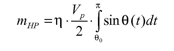
où :dPrail /dt est la variation de la pression de carburant dans la rampe commune (5) ;kb est le module de compressibilité du carburant ;Vr est le volume de la rampe commune (5) ;mHP est le débit de carburant en sortie de la pompe haute pression (6) ;mleak est la perte de débit de carburant par fuites ;minj est le débit de carburant entrant dans les cylindres (3) des injecteurs (4) ;mBackflow rate est le débit de carburant consommé par les injecteurs (4) pour leur actionnement et déchargé dans la conduite de décharge (11) ;Vp est le volume de chaque élément de pompage (15) de la pompe haute pression (6) ;η est le rendement de la pompe haute pression (6) ;θ 0 est le début de l'angle de distribution ;θ est l'angle de rotation de la pompe haute pression (6). - Procédé de commande selon la revendication 1 ou 2, et comprenant les étapes supplémentaires consistant à :amener le carburant à la pompe haute pression (6) au moyen d'une vanne de régulation (24) ;commander de manière cyclique l'ouverture et la fermeture de la vanne de régulation (24) pour réguler par étranglement le débit du carburant pris par la pompe haute pression (6) elle-même ;ajuster le débit du carburant pris par la pompe haute pression (6) en faisant varier le rapport entre la durée de l'état ouvert et la durée de l'état fermé de la vanne de régulation (24) ; etcommander la vanne de régulation (24) en synchronisme avec l'actionnement mécanique de la pompe haute pression (6) et donc avec la rotation de l'arbre d'entraînement (21).
- Procédé de commande selon la revendication 3, et comprenant l'étape de mise en phase de la commande de la vanne de régulation (24) par rapport à l'actionnement mécanique de la pompe haute pression (6), de telle sorte que l'ouverture de la vanne de régulation (24) soit commandée à une position angulaire souhaitée par rapport à l'actionnement mécanique de la pompe haute pression (6) et donc par rapport à l'arbre d'entraînement (21).
- Procédé de commande selon la revendication 3 ou 4, et comprenant les étapes supplémentaires consistant à :déterminer au moins un angle critique de la pompe haute pression (6) ; etmettre en phase la commande de la vanne de régulation (24) par rapport à l'actionnement mécanique de la pompe haute pression (6) et donc par rapport à la rotation de l'arbre d'entraînement (21), de telle sorte que la commande d'ouverture de la vanne de régulation (24) soit donnée en dehors de l'angle critique de la pompe haute pression (6).
- Procédé de commande selon l'une des revendications 1 à 5, dans lequel la phase de l'élément de pompage (15) est déterminée pendant une phase de coupure (« cut-off phase ») du moteur à combustion interne (2).
- Procédé de commande selon l'une des revendications 1 à 6, dans lequel la phase de l'élément de pompage (15) est déterminée pendant une phase de coupure (« cut-off phase ») du moteur à combustion interne (2), uniquement quand la pression de carburant Prail de la rampe commune (5) est supérieure à une valeur seuil prédéterminée donnée.
- Procédé de commande selon l'une des revendications 1 à 6, dans lequel la phase de l'élément de pompage (15) est déterminée pendant une phase de coupure (« cut-off phase ») du moteur à combustion interne (2), uniquement quand la vitesse de rotation d'un arbre d'entraînement (21) est comprise dans une plage de mesures prédéterminée.
- Procédé de commande selon l'une des revendications 1 à 8, dans lequel la position angulaire de l'arbre d'entraînement (21) à laquelle apparaît le PMH de l'élément de pompage (15) est estimée en fonction de la position angulaire de l'arbre d'entraînement (21) à laquelle la pression de carburant Prail dans la rampe commune (5) atteint un maximum relatif.
- Procédé de commande selon la revendication 9, dans lequel la position angulaire de l'arbre d'entraînement (21) à laquelle apparaît le PMH de l'élément de pompage (15) est estimée en fonction de la position angulaire de l'arbre d'entraînement (21) à laquelle la pression de carburant Prail dans la rampe commune (5) atteint un maximum relatif, corrigée par une valeur de correction angulaire.
- Procédé de commande selon la revendication 10, dans lequel la valeur de correction angulaire est constante et prédéterminée.
- Procédé de commande selon la revendication 10, dans lequel la valeur de correction angulaire est variable en fonction de la vitesse de rotation de l'arbre d'entraînement (21), de la pression de carburant Prail dans la rampe commune (5) et/ou d'une perte de débit de carburant par fuite de la rampe commune, mleak .
Priority Applications (6)
| Application Number | Priority Date | Filing Date | Title |
|---|---|---|---|
| AT07425598T ATE460582T1 (de) | 2007-09-26 | 2007-09-26 | Verfahren zur steuerung eines common-rail- direkteinspritzungsystems mit einer hochdruckkraftstoffpumpe |
| DE602007005260T DE602007005260D1 (de) | 2007-09-26 | 2007-09-26 | Verfahren zur Steuerung eines Common-Rail-Direkteinspritzungsystems mit einer Hochdruckkraftstoffpumpe |
| EP07425598A EP2042720B1 (fr) | 2007-09-26 | 2007-09-26 | Procédé de commande pour un système d'injection directe à rampe d'alimentation commune comprenant une pompe à carburant à haute pression |
| US12/234,914 US7789068B2 (en) | 2007-09-26 | 2008-09-22 | Control method of a direct injection system of the common rail type provided with a high-pressure fuel pump |
| CN200810168312.8A CN101440765B (zh) | 2007-09-26 | 2008-09-26 | 配备有高压燃料泵的共轨型直喷系统的控制方法 |
| BRPI0803628A BRPI0803628B1 (pt) | 2007-09-26 | 2008-09-26 | método de controle de um sistema de injeção direta do tipo tubo comum provido de uma bomba de combustível de alta pressão |
Applications Claiming Priority (1)
| Application Number | Priority Date | Filing Date | Title |
|---|---|---|---|
| EP07425598A EP2042720B1 (fr) | 2007-09-26 | 2007-09-26 | Procédé de commande pour un système d'injection directe à rampe d'alimentation commune comprenant une pompe à carburant à haute pression |
Publications (2)
| Publication Number | Publication Date |
|---|---|
| EP2042720A1 EP2042720A1 (fr) | 2009-04-01 |
| EP2042720B1 true EP2042720B1 (fr) | 2010-03-10 |
Family
ID=39020742
Family Applications (1)
| Application Number | Title | Priority Date | Filing Date |
|---|---|---|---|
| EP07425598A Ceased EP2042720B1 (fr) | 2007-09-26 | 2007-09-26 | Procédé de commande pour un système d'injection directe à rampe d'alimentation commune comprenant une pompe à carburant à haute pression |
Country Status (6)
| Country | Link |
|---|---|
| US (1) | US7789068B2 (fr) |
| EP (1) | EP2042720B1 (fr) |
| CN (1) | CN101440765B (fr) |
| AT (1) | ATE460582T1 (fr) |
| BR (1) | BRPI0803628B1 (fr) |
| DE (1) | DE602007005260D1 (fr) |
Families Citing this family (25)
| Publication number | Priority date | Publication date | Assignee | Title |
|---|---|---|---|---|
| DE102006031569B3 (de) * | 2006-07-07 | 2008-03-27 | Siemens Ag | Verfahren und Vorrichtung zum Betreiben einer Brennkraftmaschine |
| DE602007007331D1 (de) * | 2007-09-13 | 2010-08-05 | Magneti Marelli Spa | Verfahren zur Steuerung eines Direkteinspritzungsystems von der Common-Rail Art mit einem Absperrventil um die Flussrate einer Hochdruckkraftstoffpumpe zu regeln |
| DE102008036120B4 (de) * | 2008-08-01 | 2010-04-08 | Continental Automotive Gmbh | Verfahren zur Steuerung einer Hochdruck-Kraftstoffpumpe |
| IT1398227B1 (it) | 2009-06-09 | 2013-02-22 | Magneti Marelli Spa | Metodo per l'auto apprendimento della variazione di una caratteristica di funzionamento nominale di una pompa ad alta pressione a portata variabile in un motore a combustione interna |
| DE102010030447A1 (de) | 2010-06-23 | 2011-12-29 | Bayerische Motoren Werke Aktiengesellschaft | Verfahren zur Bestimmung der Lage eines oberen Totpunkts bei einer Kolben-Hochdruckpumpe in einer Kraftstoffversorgung eines Verbrennungsmotors |
| SE536319C2 (sv) * | 2011-12-13 | 2013-08-20 | Scania Cv Ab | Anordning och förfarande för feldetektering i ett bränsletillförselsystem hos ett motorfordon |
| EP2647824B1 (fr) * | 2012-04-05 | 2016-08-03 | Delphi International Operations Luxembourg S.à r.l. | Système de pompe à injection |
| US9903306B2 (en) | 2013-02-08 | 2018-02-27 | Cummins Inc. | System and method for acquiring pressure data from a fuel accumulator of an internal combustion engine |
| US9551631B2 (en) | 2013-02-08 | 2017-01-24 | Cummins Inc. | System and method for adapting to a variable fuel delivery cutout delay in a fuel system of an internal combustion engine |
| US9453466B2 (en) * | 2013-02-21 | 2016-09-27 | Ford Global Technologies, Llc | Methods and systems for a fuel system |
| CN103277204B (zh) * | 2013-05-30 | 2016-04-06 | 北京经纬恒润科技有限公司 | 一种高压油路建模方法及装置 |
| US9399976B2 (en) * | 2013-07-18 | 2016-07-26 | Denso International America, Inc. | Fuel delivery system containing high pressure pump with isolation valves |
| US9267460B2 (en) | 2013-07-19 | 2016-02-23 | Cummins Inc. | System and method for estimating high-pressure fuel leakage in a common rail fuel system |
| US9243598B2 (en) * | 2014-02-25 | 2016-01-26 | Ford Global Technologies, Llc | Methods for determining fuel bulk modulus in a high-pressure pump |
| DE102014217560B3 (de) * | 2014-09-03 | 2015-11-12 | Continental Automotive Gmbh | Verfahren und Vorrichtung zur Verbesserung der in den Zylindern einer Brennkraftmaschine erfolgenden Verbrennungsvorgänge |
| DE102015218258B4 (de) * | 2015-09-23 | 2017-08-24 | Continental Automotive Gmbh | Verfahren zur Raildruckregelung eines Einspritzsystems |
| DE102015221913A1 (de) * | 2015-11-09 | 2017-05-11 | Robert Bosch Gmbh | Verfahren zum Ermitteln eines Anbaulagewinkels einer Hochdruckpumpe |
| SE540744C2 (en) * | 2015-11-27 | 2018-10-30 | Scania Cv Ab | Method and system for determining pressure in a fuel accumulator tank of an engine |
| GB2554917B (en) * | 2016-10-14 | 2020-04-08 | Delphi Tech Ip Ltd | Method to determine fuel pump phasing |
| FR3060657B1 (fr) * | 2016-12-15 | 2020-12-25 | Continental Automotive France | Procede d'estimation d'un point mort haut pour une pompe haute pression d'un systeme d'injection de carburant dans un moteur de vehicule automobile |
| FR3073256B1 (fr) * | 2017-11-08 | 2021-07-30 | Renault Sas | Procede de calage pompe haute pression / vilebrequin |
| CN112020602B (zh) * | 2018-04-10 | 2023-03-28 | 康明斯公司 | 自适应高压燃料泵系统和预测泵送质量的方法 |
| JP7331776B2 (ja) * | 2020-05-21 | 2023-08-23 | トヨタ自動車株式会社 | 燃圧推定システム、データ解析装置、燃料供給装置の制御装置 |
| JP7294235B2 (ja) * | 2020-05-21 | 2023-06-20 | トヨタ自動車株式会社 | 燃圧推定システム、データ解析装置、燃料供給装置の制御装置 |
| WO2022235686A1 (fr) | 2021-05-03 | 2022-11-10 | Cummins Inc. | Systèmes et procédés d'utilisation d'injecteur de combustible comme un capteur de pression pour détecter un point mort haut pour un cylindre |
Citations (1)
| Publication number | Priority date | Publication date | Assignee | Title |
|---|---|---|---|---|
| US6353791B1 (en) * | 2000-05-04 | 2002-03-05 | Cummins, Inc. | Apparatus and method for determining engine static timing errors and overall system bandwidth |
Family Cites Families (28)
| Publication number | Priority date | Publication date | Assignee | Title |
|---|---|---|---|---|
| US5058553A (en) | 1988-11-24 | 1991-10-22 | Nippondenso Co., Ltd. | Variable-discharge high pressure pump |
| US5313924A (en) * | 1993-03-08 | 1994-05-24 | Chrysler Corporation | Fuel injection system and method for a diesel or stratified charge engine |
| US5678521A (en) * | 1993-05-06 | 1997-10-21 | Cummins Engine Company, Inc. | System and methods for electronic control of an accumulator fuel system |
| US5564391A (en) * | 1993-06-16 | 1996-10-15 | Caterpillar Inc. | Electronic control for a hydraulic-actuator unit injector fuel system and method for operating same |
| DE19644915A1 (de) | 1996-10-29 | 1998-04-30 | Bosch Gmbh Robert | Hochdruckpumpe |
| JP3834918B2 (ja) * | 1997-03-04 | 2006-10-18 | いすゞ自動車株式会社 | エンジンの燃料噴射方法及びその装置 |
| US5924403A (en) * | 1997-06-06 | 1999-07-20 | Detroit Diesel Corporation | Method for enhanced split injection in internal combustion engines |
| JP3713918B2 (ja) * | 1997-08-29 | 2005-11-09 | いすゞ自動車株式会社 | エンジンの燃料噴射方法及びその装置 |
| JPH11200990A (ja) * | 1998-01-07 | 1999-07-27 | Unisia Jecs Corp | 燃料噴射制御装置 |
| JP2000018078A (ja) * | 1998-06-30 | 2000-01-18 | Isuzu Motors Ltd | コモンレール圧力の圧力降下開始時期特定方法,並びにエンジンの燃料噴射方法及びその装置 |
| JP3794205B2 (ja) * | 1999-06-15 | 2006-07-05 | いすゞ自動車株式会社 | コモンレール式燃料噴射装置 |
| JP3633388B2 (ja) * | 1999-08-04 | 2005-03-30 | トヨタ自動車株式会社 | 内燃機関の高圧燃料ポンプ制御装置 |
| JP3849367B2 (ja) * | 1999-09-20 | 2006-11-22 | いすゞ自動車株式会社 | コモンレール式燃料噴射装置 |
| JP2001182597A (ja) * | 1999-12-24 | 2001-07-06 | Hitachi Ltd | 高圧燃料ポンプ制御装置及び筒内噴射エンジン制御装置 |
| JP3842002B2 (ja) * | 2000-03-01 | 2006-11-08 | 三菱電機株式会社 | 可変吐出量燃料供給装置 |
| DE10023227A1 (de) * | 2000-05-12 | 2001-11-22 | Bosch Gmbh Robert | Verfahren zum Bestimmen der Position eines Kolbens einer 1-Zylinder-Hochdruckpumpe eines Kraftstoffzumesssystems einer direkteinspritzenden Brennkraftmaschine |
| JP2002089401A (ja) * | 2000-09-18 | 2002-03-27 | Hitachi Ltd | 燃料供給装置 |
| JP4627603B2 (ja) * | 2001-03-15 | 2011-02-09 | 日立オートモティブシステムズ株式会社 | 燃料供給装置 |
| US6694953B2 (en) * | 2002-01-02 | 2004-02-24 | Caterpillar Inc | Utilization of a rail pressure predictor model in controlling a common rail fuel injection system |
| US7299790B2 (en) * | 2002-06-20 | 2007-11-27 | Hitachi, Ltd. | Control device of high-pressure fuel pump of internal combustion engine |
| JP3965098B2 (ja) * | 2002-09-30 | 2007-08-22 | ヤンマー株式会社 | コモンレール式燃料噴射装置の燃料圧力検出装置及びその燃料圧力検出装置を備えたコモンレール式燃料噴射装置 |
| JP2005127164A (ja) * | 2003-10-21 | 2005-05-19 | Denso Corp | コモンレール式燃料噴射装置 |
| JP4164021B2 (ja) * | 2003-12-12 | 2008-10-08 | 株式会社日立製作所 | エンジンの高圧燃料ポンプ制御装置 |
| DE10360332A1 (de) * | 2003-12-20 | 2005-07-21 | Robert Bosch Gmbh | Verfahren und Vorrichtung zum Bestimmen eines Förderintervalls einer Hochdruckpumpe |
| ATE337482T1 (de) | 2004-06-30 | 2006-09-15 | Fiat Ricerche | Hochdruckpumpe mit variabler förderrate für ein brennstoffeinspritzsystem |
| JP2006029088A (ja) * | 2004-07-12 | 2006-02-02 | Yanmar Co Ltd | 蓄圧式燃料噴射装置及びその蓄圧式燃料噴射装置を備えた内燃機関 |
| ES2282837T3 (es) * | 2004-12-23 | 2007-10-16 | C.R.F. Societa' Consortile Per Azioni | Un sistema de inyeccion de carburante con volumen de almacenamiento p ara un motor de combustion interna. |
| JP4579955B2 (ja) * | 2007-09-20 | 2010-11-10 | 日立オートモティブシステムズ株式会社 | 高圧燃料ポンプを備えた筒内噴射式内燃機関の制御装置 |
-
2007
- 2007-09-26 EP EP07425598A patent/EP2042720B1/fr not_active Ceased
- 2007-09-26 DE DE602007005260T patent/DE602007005260D1/de active Active
- 2007-09-26 AT AT07425598T patent/ATE460582T1/de not_active IP Right Cessation
-
2008
- 2008-09-22 US US12/234,914 patent/US7789068B2/en not_active Expired - Fee Related
- 2008-09-26 BR BRPI0803628A patent/BRPI0803628B1/pt not_active IP Right Cessation
- 2008-09-26 CN CN200810168312.8A patent/CN101440765B/zh not_active Expired - Fee Related
Patent Citations (1)
| Publication number | Priority date | Publication date | Assignee | Title |
|---|---|---|---|---|
| US6353791B1 (en) * | 2000-05-04 | 2002-03-05 | Cummins, Inc. | Apparatus and method for determining engine static timing errors and overall system bandwidth |
Also Published As
| Publication number | Publication date |
|---|---|
| US7789068B2 (en) | 2010-09-07 |
| BRPI0803628A2 (pt) | 2009-06-02 |
| CN101440765B (zh) | 2013-03-20 |
| ATE460582T1 (de) | 2010-03-15 |
| BRPI0803628B1 (pt) | 2018-12-26 |
| DE602007005260D1 (de) | 2010-04-22 |
| EP2042720A1 (fr) | 2009-04-01 |
| CN101440765A (zh) | 2009-05-27 |
| US20090139489A1 (en) | 2009-06-04 |
Similar Documents
| Publication | Publication Date | Title |
|---|---|---|
| EP2042720B1 (fr) | Procédé de commande pour un système d'injection directe à rampe d'alimentation commune comprenant une pompe à carburant à haute pression | |
| US7699040B2 (en) | Control method for a direct injection system of the common-rail type provided with a shut-off valve for controlling the flow rate of a high-pressure fuel pump | |
| EP1241338B1 (fr) | Système d'alimentation en carburant | |
| RU2164306C2 (ru) | Устройство управления жидкостным насосом и способ для его осуществления (варианты) | |
| US6971370B2 (en) | Common rail type fuel injection system | |
| EP2039920B1 (fr) | Procédé de contrôle pour système d'injection directe de type rail commun fourni avec robinet de sectionnement pour contrôler le débit d'une pompe à carburant haute pression | |
| US9551631B2 (en) | System and method for adapting to a variable fuel delivery cutout delay in a fuel system of an internal combustion engine | |
| EP2835518A1 (fr) | Procédé pour déterminer le module de compressibilité d'un combustible | |
| US20150112576A1 (en) | Pump control apparatus for fuel supply system of fuel-injection engine | |
| JP2008291808A (ja) | コモンレール式燃料噴射装置及び高圧ポンプの圧送特性補償方法 | |
| EP1201905A2 (fr) | Dispositif de detection de défaut dans un système d'alimentation en carburant haute pression | |
| JP5892649B2 (ja) | 高圧燃料ポンプ基準点検出方法及びコモンレール式燃料噴射制御装置 | |
| US10837383B2 (en) | Method for estimating a top dead centre for a high-pressure pump of a fuel injection system in an automotive vehicle engine | |
| EP1674718A1 (fr) | Système d'injection accumulateur pour moteur a combustion interne | |
| EP2273092B1 (fr) | Procédé d'apprentissage de paramètres d'une soupape de régulation d'une pompe d'alimentation en carburant de haute pression avec débit d'alimentation variable | |
| EP2031229A2 (fr) | Appareil pour contrôler la quantité de carburant à pulvériser réellement dans un mode à injection multiple | |
| JP2003201865A (ja) | 蓄圧式燃料噴射装置 | |
| JPH11125134A (ja) | エンジンの燃料噴射制御装置 | |
| JP4656087B2 (ja) | 燃料噴射制御装置およびそれを用いた燃料噴射システム | |
| EP2143913A1 (fr) | Dispositif de détection de position haute de came de pompe haute pression | |
| JP2010275991A (ja) | 燃料供給システムの制御装置 | |
| JPH09170478A (ja) | ディーゼルエンジンの燃料噴射制御方法 | |
| JPH09151772A (ja) | 燃料噴射制御装置 | |
| JPH10252526A (ja) | ディーゼル機関の燃料噴射量検出装置 | |
| JPH06288315A (ja) | 燃料噴射ポンプのタイマ装置 |
Legal Events
| Date | Code | Title | Description |
|---|---|---|---|
| PUAI | Public reference made under article 153(3) epc to a published international application that has entered the european phase |
Free format text: ORIGINAL CODE: 0009012 |
|
| 17P | Request for examination filed |
Effective date: 20081213 |
|
| AK | Designated contracting states |
Kind code of ref document: A1 Designated state(s): AT BE BG CH CY CZ DE DK EE ES FI FR GB GR HU IE IS IT LI LT LU LV MC MT NL PL PT RO SE SI SK TR |
|
| AX | Request for extension of the european patent |
Extension state: AL BA HR MK RS |
|
| 17Q | First examination report despatched |
Effective date: 20090319 |
|
| GRAP | Despatch of communication of intention to grant a patent |
Free format text: ORIGINAL CODE: EPIDOSNIGR1 |
|
| AKX | Designation fees paid |
Designated state(s): AT BE BG CH CY CZ DE DK EE ES FI FR GB GR HU IE IS IT LI LT LU LV MC MT NL PL PT RO SE SI SK TR |
|
| GRAS | Grant fee paid |
Free format text: ORIGINAL CODE: EPIDOSNIGR3 |
|
| GRAA | (expected) grant |
Free format text: ORIGINAL CODE: 0009210 |
|
| RAP1 | Party data changed (applicant data changed or rights of an application transferred) |
Owner name: MAGNETI MARELLI S.P.A. |
|
| AK | Designated contracting states |
Kind code of ref document: B1 Designated state(s): AT BE BG CH CY CZ DE DK EE ES FI FR GB GR HU IE IS IT LI LT LU LV MC MT NL PL PT RO SE SI SK TR |
|
| REG | Reference to a national code |
Ref country code: GB Ref legal event code: FG4D |
|
| REG | Reference to a national code |
Ref country code: CH Ref legal event code: EP |
|
| REG | Reference to a national code |
Ref country code: IE Ref legal event code: FG4D |
|
| REF | Corresponds to: |
Ref document number: 602007005260 Country of ref document: DE Date of ref document: 20100422 Kind code of ref document: P |
|
| REG | Reference to a national code |
Ref country code: NL Ref legal event code: VDEP Effective date: 20100310 |
|
| PG25 | Lapsed in a contracting state [announced via postgrant information from national office to epo] |
Ref country code: LT Free format text: LAPSE BECAUSE OF FAILURE TO SUBMIT A TRANSLATION OF THE DESCRIPTION OR TO PAY THE FEE WITHIN THE PRESCRIBED TIME-LIMIT Effective date: 20100310 |
|
| LTIE | Lt: invalidation of european patent or patent extension |
Effective date: 20100310 |
|
| PG25 | Lapsed in a contracting state [announced via postgrant information from national office to epo] |
Ref country code: SI Free format text: LAPSE BECAUSE OF FAILURE TO SUBMIT A TRANSLATION OF THE DESCRIPTION OR TO PAY THE FEE WITHIN THE PRESCRIBED TIME-LIMIT Effective date: 20100310 Ref country code: FI Free format text: LAPSE BECAUSE OF FAILURE TO SUBMIT A TRANSLATION OF THE DESCRIPTION OR TO PAY THE FEE WITHIN THE PRESCRIBED TIME-LIMIT Effective date: 20100310 Ref country code: LV Free format text: LAPSE BECAUSE OF FAILURE TO SUBMIT A TRANSLATION OF THE DESCRIPTION OR TO PAY THE FEE WITHIN THE PRESCRIBED TIME-LIMIT Effective date: 20100310 Ref country code: PL Free format text: LAPSE BECAUSE OF FAILURE TO SUBMIT A TRANSLATION OF THE DESCRIPTION OR TO PAY THE FEE WITHIN THE PRESCRIBED TIME-LIMIT Effective date: 20100310 Ref country code: AT Free format text: LAPSE BECAUSE OF FAILURE TO SUBMIT A TRANSLATION OF THE DESCRIPTION OR TO PAY THE FEE WITHIN THE PRESCRIBED TIME-LIMIT Effective date: 20100310 |
|
| PG25 | Lapsed in a contracting state [announced via postgrant information from national office to epo] |
Ref country code: ES Free format text: LAPSE BECAUSE OF FAILURE TO SUBMIT A TRANSLATION OF THE DESCRIPTION OR TO PAY THE FEE WITHIN THE PRESCRIBED TIME-LIMIT Effective date: 20100621 Ref country code: EE Free format text: LAPSE BECAUSE OF FAILURE TO SUBMIT A TRANSLATION OF THE DESCRIPTION OR TO PAY THE FEE WITHIN THE PRESCRIBED TIME-LIMIT Effective date: 20100310 Ref country code: CY Free format text: LAPSE BECAUSE OF FAILURE TO SUBMIT A TRANSLATION OF THE DESCRIPTION OR TO PAY THE FEE WITHIN THE PRESCRIBED TIME-LIMIT Effective date: 20100310 Ref country code: BE Free format text: LAPSE BECAUSE OF FAILURE TO SUBMIT A TRANSLATION OF THE DESCRIPTION OR TO PAY THE FEE WITHIN THE PRESCRIBED TIME-LIMIT Effective date: 20100310 Ref country code: GR Free format text: LAPSE BECAUSE OF FAILURE TO SUBMIT A TRANSLATION OF THE DESCRIPTION OR TO PAY THE FEE WITHIN THE PRESCRIBED TIME-LIMIT Effective date: 20100611 Ref country code: NL Free format text: LAPSE BECAUSE OF FAILURE TO SUBMIT A TRANSLATION OF THE DESCRIPTION OR TO PAY THE FEE WITHIN THE PRESCRIBED TIME-LIMIT Effective date: 20100310 Ref country code: RO Free format text: LAPSE BECAUSE OF FAILURE TO SUBMIT A TRANSLATION OF THE DESCRIPTION OR TO PAY THE FEE WITHIN THE PRESCRIBED TIME-LIMIT Effective date: 20100310 Ref country code: SE Free format text: LAPSE BECAUSE OF FAILURE TO SUBMIT A TRANSLATION OF THE DESCRIPTION OR TO PAY THE FEE WITHIN THE PRESCRIBED TIME-LIMIT Effective date: 20100310 |
|
| PG25 | Lapsed in a contracting state [announced via postgrant information from national office to epo] |
Ref country code: SK Free format text: LAPSE BECAUSE OF FAILURE TO SUBMIT A TRANSLATION OF THE DESCRIPTION OR TO PAY THE FEE WITHIN THE PRESCRIBED TIME-LIMIT Effective date: 20100310 Ref country code: IS Free format text: LAPSE BECAUSE OF FAILURE TO SUBMIT A TRANSLATION OF THE DESCRIPTION OR TO PAY THE FEE WITHIN THE PRESCRIBED TIME-LIMIT Effective date: 20100710 Ref country code: BG Free format text: LAPSE BECAUSE OF FAILURE TO SUBMIT A TRANSLATION OF THE DESCRIPTION OR TO PAY THE FEE WITHIN THE PRESCRIBED TIME-LIMIT Effective date: 20100610 Ref country code: CZ Free format text: LAPSE BECAUSE OF FAILURE TO SUBMIT A TRANSLATION OF THE DESCRIPTION OR TO PAY THE FEE WITHIN THE PRESCRIBED TIME-LIMIT Effective date: 20100310 |
|
| PLBE | No opposition filed within time limit |
Free format text: ORIGINAL CODE: 0009261 |
|
| STAA | Information on the status of an ep patent application or granted ep patent |
Free format text: STATUS: NO OPPOSITION FILED WITHIN TIME LIMIT |
|
| PG25 | Lapsed in a contracting state [announced via postgrant information from national office to epo] |
Ref country code: DK Free format text: LAPSE BECAUSE OF FAILURE TO SUBMIT A TRANSLATION OF THE DESCRIPTION OR TO PAY THE FEE WITHIN THE PRESCRIBED TIME-LIMIT Effective date: 20100310 Ref country code: PT Free format text: LAPSE BECAUSE OF FAILURE TO SUBMIT A TRANSLATION OF THE DESCRIPTION OR TO PAY THE FEE WITHIN THE PRESCRIBED TIME-LIMIT Effective date: 20100712 |
|
| 26N | No opposition filed |
Effective date: 20101213 |
|
| PG25 | Lapsed in a contracting state [announced via postgrant information from national office to epo] |
Ref country code: MC Free format text: LAPSE BECAUSE OF NON-PAYMENT OF DUE FEES Effective date: 20100930 |
|
| PG25 | Lapsed in a contracting state [announced via postgrant information from national office to epo] |
Ref country code: IE Free format text: LAPSE BECAUSE OF NON-PAYMENT OF DUE FEES Effective date: 20100926 |
|
| PG25 | Lapsed in a contracting state [announced via postgrant information from national office to epo] |
Ref country code: MT Free format text: LAPSE BECAUSE OF FAILURE TO SUBMIT A TRANSLATION OF THE DESCRIPTION OR TO PAY THE FEE WITHIN THE PRESCRIBED TIME-LIMIT Effective date: 20100310 |
|
| REG | Reference to a national code |
Ref country code: CH Ref legal event code: PL |
|
| GBPC | Gb: european patent ceased through non-payment of renewal fee |
Effective date: 20110926 |
|
| PG25 | Lapsed in a contracting state [announced via postgrant information from national office to epo] |
Ref country code: CH Free format text: LAPSE BECAUSE OF NON-PAYMENT OF DUE FEES Effective date: 20110930 Ref country code: LI Free format text: LAPSE BECAUSE OF NON-PAYMENT OF DUE FEES Effective date: 20110930 |
|
| PG25 | Lapsed in a contracting state [announced via postgrant information from national office to epo] |
Ref country code: GB Free format text: LAPSE BECAUSE OF NON-PAYMENT OF DUE FEES Effective date: 20110926 |
|
| PG25 | Lapsed in a contracting state [announced via postgrant information from national office to epo] |
Ref country code: LU Free format text: LAPSE BECAUSE OF NON-PAYMENT OF DUE FEES Effective date: 20100926 Ref country code: HU Free format text: LAPSE BECAUSE OF FAILURE TO SUBMIT A TRANSLATION OF THE DESCRIPTION OR TO PAY THE FEE WITHIN THE PRESCRIBED TIME-LIMIT Effective date: 20100911 |
|
| PG25 | Lapsed in a contracting state [announced via postgrant information from national office to epo] |
Ref country code: TR Free format text: LAPSE BECAUSE OF FAILURE TO SUBMIT A TRANSLATION OF THE DESCRIPTION OR TO PAY THE FEE WITHIN THE PRESCRIBED TIME-LIMIT Effective date: 20100310 |
|
| REG | Reference to a national code |
Ref country code: FR Ref legal event code: PLFP Year of fee payment: 10 |
|
| REG | Reference to a national code |
Ref country code: FR Ref legal event code: PLFP Year of fee payment: 11 |
|
| REG | Reference to a national code |
Ref country code: FR Ref legal event code: PLFP Year of fee payment: 12 |
|
| PGFP | Annual fee paid to national office [announced via postgrant information from national office to epo] |
Ref country code: FR Payment date: 20210819 Year of fee payment: 15 Ref country code: IT Payment date: 20210824 Year of fee payment: 15 |
|
| PGFP | Annual fee paid to national office [announced via postgrant information from national office to epo] |
Ref country code: DE Payment date: 20210818 Year of fee payment: 15 |
|
| REG | Reference to a national code |
Ref country code: DE Ref legal event code: R119 Ref document number: 602007005260 Country of ref document: DE |
|
| PG25 | Lapsed in a contracting state [announced via postgrant information from national office to epo] |
Ref country code: FR Free format text: LAPSE BECAUSE OF NON-PAYMENT OF DUE FEES Effective date: 20220930 Ref country code: DE Free format text: LAPSE BECAUSE OF NON-PAYMENT OF DUE FEES Effective date: 20230401 |
|
| PG25 | Lapsed in a contracting state [announced via postgrant information from national office to epo] |
Ref country code: IT Free format text: LAPSE BECAUSE OF NON-PAYMENT OF DUE FEES Effective date: 20220926 |