EP0899602A2 - Procédé et dispositif de commande d'un modulateur optique, pour mesurer et compenser la dispersion dans une ligne de transmission optique - Google Patents
Procédé et dispositif de commande d'un modulateur optique, pour mesurer et compenser la dispersion dans une ligne de transmission optique Download PDFInfo
- Publication number
- EP0899602A2 EP0899602A2 EP98105842A EP98105842A EP0899602A2 EP 0899602 A2 EP0899602 A2 EP 0899602A2 EP 98105842 A EP98105842 A EP 98105842A EP 98105842 A EP98105842 A EP 98105842A EP 0899602 A2 EP0899602 A2 EP 0899602A2
- Authority
- EP
- European Patent Office
- Prior art keywords
- optical
- pulse
- transmission line
- dispersion
- driving voltage
- Prior art date
- Legal status (The legal status is an assumption and is not a legal conclusion. Google has not performed a legal analysis and makes no representation as to the accuracy of the status listed.)
- Withdrawn
Links
Images


Classifications
-
- H—ELECTRICITY
- H04—ELECTRIC COMMUNICATION TECHNIQUE
- H04B—TRANSMISSION
- H04B10/00—Transmission systems employing electromagnetic waves other than radio-waves, e.g. infrared, visible or ultraviolet light, or employing corpuscular radiation, e.g. quantum communication
- H04B10/25—Arrangements specific to fibre transmission
- H04B10/2507—Arrangements specific to fibre transmission for the reduction or elimination of distortion or dispersion
- H04B10/2513—Arrangements specific to fibre transmission for the reduction or elimination of distortion or dispersion due to chromatic dispersion
- H04B10/2525—Arrangements specific to fibre transmission for the reduction or elimination of distortion or dispersion due to chromatic dispersion using dispersion-compensating fibres
-
- G—PHYSICS
- G02—OPTICS
- G02F—OPTICAL DEVICES OR ARRANGEMENTS FOR THE CONTROL OF LIGHT BY MODIFICATION OF THE OPTICAL PROPERTIES OF THE MEDIA OF THE ELEMENTS INVOLVED THEREIN; NON-LINEAR OPTICS; FREQUENCY-CHANGING OF LIGHT; OPTICAL LOGIC ELEMENTS; OPTICAL ANALOGUE/DIGITAL CONVERTERS
- G02F1/00—Devices or arrangements for the control of the intensity, colour, phase, polarisation or direction of light arriving from an independent light source, e.g. switching, gating or modulating; Non-linear optics
- G02F1/01—Devices or arrangements for the control of the intensity, colour, phase, polarisation or direction of light arriving from an independent light source, e.g. switching, gating or modulating; Non-linear optics for the control of the intensity, phase, polarisation or colour
- G02F1/03—Devices or arrangements for the control of the intensity, colour, phase, polarisation or direction of light arriving from an independent light source, e.g. switching, gating or modulating; Non-linear optics for the control of the intensity, phase, polarisation or colour based on ceramics or electro-optical crystals, e.g. exhibiting Pockels effect or Kerr effect
- G02F1/0327—Operation of the cell; Circuit arrangements
-
- H—ELECTRICITY
- H04—ELECTRIC COMMUNICATION TECHNIQUE
- H04B—TRANSMISSION
- H04B10/00—Transmission systems employing electromagnetic waves other than radio-waves, e.g. infrared, visible or ultraviolet light, or employing corpuscular radiation, e.g. quantum communication
- H04B10/25—Arrangements specific to fibre transmission
- H04B10/2507—Arrangements specific to fibre transmission for the reduction or elimination of distortion or dispersion
- H04B10/2513—Arrangements specific to fibre transmission for the reduction or elimination of distortion or dispersion due to chromatic dispersion
- H04B10/25137—Arrangements specific to fibre transmission for the reduction or elimination of distortion or dispersion due to chromatic dispersion using pulse shaping at the transmitter, e.g. pre-chirping or dispersion supported transmission [DST]
-
- G—PHYSICS
- G02—OPTICS
- G02F—OPTICAL DEVICES OR ARRANGEMENTS FOR THE CONTROL OF LIGHT BY MODIFICATION OF THE OPTICAL PROPERTIES OF THE MEDIA OF THE ELEMENTS INVOLVED THEREIN; NON-LINEAR OPTICS; FREQUENCY-CHANGING OF LIGHT; OPTICAL LOGIC ELEMENTS; OPTICAL ANALOGUE/DIGITAL CONVERTERS
- G02F1/00—Devices or arrangements for the control of the intensity, colour, phase, polarisation or direction of light arriving from an independent light source, e.g. switching, gating or modulating; Non-linear optics
- G02F1/01—Devices or arrangements for the control of the intensity, colour, phase, polarisation or direction of light arriving from an independent light source, e.g. switching, gating or modulating; Non-linear optics for the control of the intensity, phase, polarisation or colour
- G02F1/21—Devices or arrangements for the control of the intensity, colour, phase, polarisation or direction of light arriving from an independent light source, e.g. switching, gating or modulating; Non-linear optics for the control of the intensity, phase, polarisation or colour by interference
- G02F1/212—Mach-Zehnder type
-
- G—PHYSICS
- G02—OPTICS
- G02F—OPTICAL DEVICES OR ARRANGEMENTS FOR THE CONTROL OF LIGHT BY MODIFICATION OF THE OPTICAL PROPERTIES OF THE MEDIA OF THE ELEMENTS INVOLVED THEREIN; NON-LINEAR OPTICS; FREQUENCY-CHANGING OF LIGHT; OPTICAL LOGIC ELEMENTS; OPTICAL ANALOGUE/DIGITAL CONVERTERS
- G02F2203/00—Function characteristic
- G02F2203/25—Frequency chirping of an optical modulator; Arrangements or methods for the pre-set or tuning thereof
-
- G—PHYSICS
- G02—OPTICS
- G02F—OPTICAL DEVICES OR ARRANGEMENTS FOR THE CONTROL OF LIGHT BY MODIFICATION OF THE OPTICAL PROPERTIES OF THE MEDIA OF THE ELEMENTS INVOLVED THEREIN; NON-LINEAR OPTICS; FREQUENCY-CHANGING OF LIGHT; OPTICAL LOGIC ELEMENTS; OPTICAL ANALOGUE/DIGITAL CONVERTERS
- G02F2203/00—Function characteristic
- G02F2203/26—Pulse shaping; Apparatus or methods therefor
-
- H—ELECTRICITY
- H04—ELECTRIC COMMUNICATION TECHNIQUE
- H04B—TRANSMISSION
- H04B2210/00—Indexing scheme relating to optical transmission systems
- H04B2210/25—Distortion or dispersion compensation
- H04B2210/252—Distortion or dispersion compensation after the transmission line, i.e. post-compensation
-
- H—ELECTRICITY
- H04—ELECTRIC COMMUNICATION TECHNIQUE
- H04B—TRANSMISSION
- H04B2210/00—Indexing scheme relating to optical transmission systems
- H04B2210/25—Distortion or dispersion compensation
- H04B2210/254—Distortion or dispersion compensation before the transmission line, i.e. pre-compensation
Definitions
- the present invention relates to the driving of an optical modulator and, more particularly, to the driving of an optical modulator to measure, and compensator for, dispersion in an optical transmission line.
- Optical transmission systems using fiber optical transmission lines are being used to transmit relatively large amounts of information. For example, optical transmission systems at 10 Gb/s are now in practical use. However, as users require larger amounts of information to be rapidly transmitted, and as more users are connected to the systems, a further increase in the capacity of optical transmission systems is required.
- wavelength dispersion increases by 18 ps/nm/km. This increase in wavelength dispersion is relatively high, thereby requiring dispersion compensation to be performed.
- the range of dispersion tolerance is relatively large, and dispersion compensation can be performed by commonly applying a dispersion compensator having a predetermined dispersion value.
- a dispersion compensator having a predetermined dispersion value.
- the dispersion tolerance is about 800 ps/nm.
- the dispersion compensation tolerance is only 30 ps/nm. Therefore, accurate dispersion compensation is required.
- the amount of dispersion is not correctly computed at a number of points.
- the amount of the dispersion compensation should be appropriately set for each of such intermediate points by accurately measuring the amount and change of dispersion.
- DSF 1.55 ⁇ m non-dispersion shift fibers
- the dispersion compensation tolerance is very small so that dispersion compensation is required even if the 1.55 ⁇ m non-dispersion shift fiber is used.
- the amount of dispersion compensation should be constantly set to an optimum value to further prevent deterioration in transmission with time, as with the 1.3 ⁇ m non-dispersion single mode fiber.
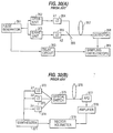
- FIG. 30(A) illustrates a twin-pulse method of measuring the wavelength dispersion.
- a group delay time difference is directly measured from the interval of pulses, to measure the wavelength dispersion.
- a pulse signal output from a pulse generator 351 is provided to laser diodes 354 and 355 through drive units 352 and 353, respectively.
- laser diode 354 Upon receipt of a pulse signal from drive unit 352, laser diode 354 outputs an optical pulse having a wavelength ⁇ 1.
- laser diode 355 Upon receipt of a pulse signal from drive unit 353, laser diode 355 outputs an optical pulse having a wavelength ⁇ 2.
- optical pulse having the wavelength ⁇ 1 output from laser diode 354 and the optical pulse having the wavelength ⁇ 2 output from laser diode 355 are provided to an optical fiber 357 through a half mirror 356, and transmitted to a detector 358 through optical fiber 357.
- sampling oscilloscope 359 compares the arrival time of the pulse signal received from pulse generator 351 through a delay circuit 360 with the arrival time of the optical pulses detected by detector 358. The amount of dispersion is obtained by detecting the delay difference between the two optical pulses after transmission through optical fiber 357.
- FIG. 30(B) illustrates a phase method of measuring the wavelength dispersion.
- the group delay time difference is not directly measured, but the wavelength dispersion is obtained from the phase difference between the optical modulation signals generated by the group delay time difference.
- a synthesizer 371 modulates an optical signal output from laser diodes 372 through 374.
- Laser diode 372 outputs an optical signal having a wavelength ⁇ 1
- laser diode 373 outputs an optical signal having a wavelength ⁇ 2
- laser diode 374 outputs an optical signal having a wavelength ⁇ 3.
- the optical signals output from laser diodes 372 through 374 are switched by an optical switch 375, provided to an optical fiber 376, and transmitted to an avalanche photodiode 377 through optical fiber 376.
- Avalanche photodiode 377 converts the optical signal transmitted through optical fiber 376 into an electric signal, and outputs the electric signal to a vector voltmeter 379 through an amplifier 378.
- Vector voltmeter 379 compares the electric signal transmitted from synthesizer 371 with the electric signal transmitted from amplifier 378, and obtains the phase difference between the optical modulation signals, thereby computing the amount of dispersion.
- Objects of the present invention are achieved by providing an optical modulator which produces an optical output at a power level which increases and decreases in accordance with an increasing driving voltage for driving the optical modulator.
- a driving voltage setting device sets the driving voltage to increase and decrease the power level of the optical output.
- Objects of the present invention are also achieved by providing an optical modulator which modulates an input light to produce a plurality of optical pulses having different wavelengths in accordance with a single pulse driving voltage for driving the optical modulator.
- a driving voltage generator generates the pulse driving voltage.
- Objects of the present invention are achieved by providing a first optical modulator which modulates a first light and provides the modulated first light to a transmission line.
- a second optical modulator modulates a second light and provides the modulated second light to the transmission line.
- An optical device such as a filter, retrieves the second light from the transmission line.
- a dispersion computation device computes an amount of dispersion in the transmission from the retrieved second light.
- a driving voltage generator which generates a pulse driving voltage having a rising edge and a decaying edge.
- An optical modulator produces a first pulse at the rising edge of the pulse driving voltage and a second pulse at the decaying edge of the pulse driving voltage.
- the first and second pulses are transmitted through a transmission line.
- a detection device detects the first and second pulses after being transmitted through the transmission line.
- the amount of dispersion in the transmission line can then be computed from the time interval between the detected first and second pulses.
- the frequency of the first pulse is determined by the slope of the rising edge of the pulse driving voltage and the frequency of the second pulse is determined by the slope of the decaying edge of the pulse driving voltage.
- Objects of the present invention are further achieved by providing a Mach-Zehnder modulator having a corresponding half-wavelength voltage V ⁇ and being driven by a pulse driving voltage.
- the pulse driving voltage has a rising edge and a decaying edge and exceeds V ⁇ so that the Mach-Zehnder modulator produces a first pulse at the rising edge of the pulse driving voltage and a second pulse at the decaying edge of the pulse driving voltage.
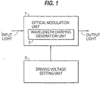
- FIG. 1 is a diagram illustrating an optical pulse generation apparatus, according to an embodiment of the present invention.
- an optical modulation unit 1 modulates an input light based on a driving voltage provided from a driving voltage setting unit 3.
- Optical modulation unit 1 increases or decreases the optical output in accordance with an increasing driving voltage. Therefore, by setting the range of the driving voltage to a range in which the optical output increases or decreases, an optical pulse is output by increasing the driving voltage. As a result, a plurality of optical pulses can be output if driving voltage setting unit 3 inputs a single pulse voltage to optical modulation unit 1.
- Optical modulation unit 1 includes a wavelength chirping generation unit 2.
- Wavelength chirping generation unit 2 generates a wavelength chirping corresponding to the driving voltage increment ratio (that is, the "slope"). Therefore, the wavelength of the optical pulse output from optical modulation unit 1 when the driving voltage increases is different from the wavelength of the optical pulse output from optical modulation unit 1 when the driving voltage decreases.
- optical modulation unit 1 outputs a plurality of optical pulses having different wavelengths even if driving voltage setting unit 3 only inputs a single pulse voltage to optical modulation unit 1.
- optical modulation unit 1 by providing an input light from a single light source, optical modulation unit 1 generates a plurality of optical pulses having different wavelengths. That is, a plurality of optical pulses having different wavelengths can be generated with a simple configuration. As a result, an optical transmission system can be smaller even when optical modulation unit 1 and driving voltage setting unit 3 are incorporated into the optical transmission system as signal sources for the dispersion measurement.
- the optical transmission system can constantly perform dispersion measurement. If the amount of dispersion compensation in the optical transmission system is set to an optimum value, then the optical transmission can be correctly performed even if dispersion compensation tolerance is small.
- FIG. 2 is a diagram illustrating an optical modulator, according to an embodiment of the present invention.
- an optical modulation unit 12 modulates an input light according to a modulation signal or a pulse signal provided by a switching unit 11.
- Optical modulation unit 12 increases or decreases an optical output with an increasing driving voltage.
- an optical pulse can be output at the rise time and the decay time of a pulse signal by setting the driving range through a pulse signal to a range in which an optical output increases or decreases. Therefore, a plurality of optical pulses can be output only by providing a single pulse voltage to optical modulation unit 1.
- Switching unit 11 provides a modulation signal for optical modulation unit 12 when a main signal is modulated, and provides a pulse signal for optical modulation unit 12 when dispersion measurement is made. Therefore, a single optical modulation unit 12 can be shared between the modulation of a main signal and the dispersion measurement, thereby reducing the size of the optical transmission system.
- Described below in detail is an example of a Mach-Zehnder modulator used as an optical modulation unit.
- Eout (t) E0/ ⁇ 2 ⁇ cos ⁇ 0 t-A (V) + cos( ⁇ 0 t+B (V)) ⁇
- a (V) a(Vin+BIA)
- B (V) b(Vin+BIA)
- Vin indicates a driving voltage input to electrodes 24a and 24b
- BIA indicates a bias voltage of a Mach-Zehnder modulator
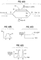
- FIGS. 4(A), 4(B), 4(C) and 4(D) are diagrams illustrating a method of driving the Mach-Zehnder modulator, according to an embodiment of the present invention. More specifically, FIG. 4(A) is a diagram illustrating a Mach-Zehnder modulator. FIG. 4(B) is a graph illustrating a pulse driving voltage provided to the modulator. FIG. 4(C) is a diagram illustrating the optical power versus time of the modulator. FIG. 4(D) is a graph illustrating pulses output by the optical modulator in accordance with the pulse driving voltage in FIG. 4(B).
- optical pulse 37 is output from optical waveguide 33 at the time t2 corresponding to the decay time of pulse voltage 35. Since the differentiation value at the decay time of the pulse voltage 35 is negative, the wavelength of the optical pulse 37 is shifted by - ⁇ into ⁇ - ⁇ .
- FIGS. 6(A)(1), 6(A)(2), 6(A)(3), 6(B)(1), 6(B)(2) and 6(B)(3) are diagrams illustrating a method of generating an optical pulse when waveform chirping is generated, according to an embodiment of the present invention.
- a wavelength chirping 38' corresponding to the differentiation value of the driving voltage Vin is generated when the driving voltage Vin decays at time t3, and optical pulse 38 having the wavelength ⁇ - ⁇ is generated.
- a wavelength chirping 39' corresponding to the differentiation value of the driving voltage Vin is generated when the driving voltage Vin rises at time t4, and optical pulse 39 having the wavelength ⁇ + ⁇ is generated.
- a Mach-Zehnder modulator normally modulates data at a half-wavelength voltage V ⁇ , but can generate short pulses at the rise time and the decay time of a driving waveform by modulating the data at a driving voltage 2V ⁇ which is double the half-wavelength voltage V ⁇ .
- the signs for the wavelength chirping ⁇ are opposite between the rise time and the decay time of the driving waveform, thereby assigning the two generated short pulses with different wavelengths ⁇ + ⁇ and ⁇ - ⁇ .
- the pulse interval is extended by a group delay difference and changed from the pulse interval d before the transmission to the pulse interval d + ⁇ d after the transmission.
- ⁇ d D ⁇ L ⁇ c
- D (ps/nm/km) indicates a dispersion value of a transmission line
- L(km) indicates a transmission distance
- ⁇ c indicates the ⁇ of a pulse peak.
- detecting the change ⁇ d in pulse interval gives a dispersion value D in a transmission line.
- the change ⁇ d in pulse interval can be directly read through, for example, a sampling oscilloscope.
- simple control can be performed by preliminarily adjusting the pulse interval d.
- FIGS. 7(A)(1), 7(A)(2), 7(A)(3), 7(B)(1), 7(B)(2) and 7(B)(3) are diagrams illustrating a method of generating an optical pulse when the pulse width of a driving voltage Vin is changed, according to an embodiment of the present invention.
- an optical pulse 505 is generated at time t3 when pulse signal 504 rises, and an optical pulse 506 is generated at time t4 when pulse signal 504 decays.
- the wavelength chirping corresponding to the differentiation value at the rise time of pulse signal 504 is generated in optical pulse 505. Therefore, the wavelength of optical pulse 505 is ⁇ 1.
- the wavelength chirping corresponding to the differentiation value at the decay time of pulse signal 504 is generated in optical pulse 506. Therefore, the wavelength of optical pulse 506 is ⁇ 2.
- FIGS. 8(A)(1), 8(A)(2), 8(A)(3), 8(B)(1), 8(B)(2) and 8(B)(3) are diagrams illustrating a method of generating an optical pulse when the slope of a driving voltage is changed, according to an embodiment of the present invention.
- the wavelength chirping corresponding to the differentiation value -dV1 at the decay time of pulse signal 601 is generated in optical pulse 603. Therefore, the wavelength of optical pulse 603 is ⁇ 2.
- the wavelength chirping corresponding to the differentiation value -dV2 at the decay time of pulse signal 604 is generated in optical pulse 606. Therefore, the wavelength of optical pulse 606 is ⁇ 3.
- the present invention uses an optical modulator, such as a Mach-Zehnder modulator, in a much different manner than conventional techniques.
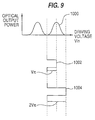
- FIG. 9 is a diagram illustrating a comparison of a convention pulse driving voltage and a pulse driving voltage according to an embodiment of the present invention.
- a Mach-Zehnder modulator has an output power versus driving voltage characteristic curve indicating a periodic waveform 1000.
- Waveform 1000 has a half-wavelength voltage V ⁇ .
- a Mach-Zehnder modulator is driven with a pulse driving voltage having a height of V ⁇ , such as pulse driving voltage 1002, to produce either an optical "1" or "0".
- the optical output power of a Mach-Zehnder modulator increases and decreases in accordance with an increasing and decreasing driving voltage, respectively.
- a modulator such as a Mach-Zehnder modulator
- a pulse driving voltage that exceeds the half-wavelength voltage V ⁇ .
- a Mach-Zehnder modulator is driven with a pulse driving voltage having a height of 2V ⁇ , such as pulse driving voltage 1004. Therefore, according to embodiments of the present invention, the optical output power of the Mach-Zehnder modulator increases and decreases in accordance with an increasing driving voltage. In other words, the driving voltage does not have to decrease to produce a decreasing optical output power.
- an optical modulator such as a Mach-Zehnder modulator
- a single pulse driving voltage which causes the optical modulator to produce a plurality of optical pulses.
- FIGS. 10(A) and 10(B) are diagrams illustrating the driving of a Mach-Zehnder modulator with a single pulse to produce a plurality of optical pulses.
- a single pulse driving voltage 1006 is applied to a Mach-Zehnder modulator.
- a plurality of optical pulses will be output by the Mach-Zehnder modulator.
- the wavelength of the pulses can be changed by changing the slope of the rising and decaying times of the pulse driving voltage. Further, time intervals between pulses can be changed by changing the duration of the pulse driving voltage.
- a Mach-Zehnder modulator is used to generate an optical "1" or "0". For this purpose, it is not necessary to use a driving voltage exceeding the half-wavelength voltage V ⁇ .
- a Mach-Zehnder modulator is used to measure, and compensate for, dispersion. Conventionally, a Mach-Zehnder modulator is not used for this purpose. This difference in the use of a Mach-Zehnder modulator is an important reason why a Mach-Zehnder modulator is not conventionally driven at a voltage exceeding the half-wavelength voltage V ⁇ .
- FIGS. 11(A), 11(B) and 11(C) are diagrams illustrating waveforms from an experiment on optical pulse transmission, according to an embodiment of the present invention.
- FIG. 11(A) illustrates a transmission pulse string before being transmitted through a single mode fiber and having a transmission interval L1 of 400ps.
- FIG. 11(B) illustrates the pulse string after transmission through 25km of the single mode fiber. As shown in FIG. 11(B), the interval between the optical pulses is extended to L2.
- FIG. 11(C) illustrates the pulse string after transmission through 50km of the single mode fiber. As shown in FIG. 11(C), the interval of optical pulses is extended to L3.
- the interval between the optical pulses depends on the dispersion value (length of the transmission line).
- the wavelength dispersion of the single mode fiber used in this experiment is about 17 ps/nm/km.
- measuring the optical pulse interval after the transmission through the single mode fiber enables the dispersion measurement and dispersion compensation of a fiber transmission line working at super-high speed transmission speeds through an existing transmission line to be easily performed at low cost.
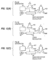
- FIGS. 12(A), 12(B) and 12(C) are diagrams illustrating an optical pulse generation apparatus, according to an embodiment of the present invention.
- laser light emitted from a laser diode 41 is input to a Mach-Zehnder modulator 42 and, simultaneously, a pulse signal 401 generated by a pulse generator 43 is input to Mach-Zehnder modulator 42.
- pulse generator 43 drives Mach-Zehnder modulator 42 on one side only, and sets the driving voltage Vin to double the half-wavelength voltage V ⁇ .
- two optical pulses 402 and 403 are output from Mach-Zehnder modulator 42, and a wavelength chirping is generated corresponding to the increment ratio of the pulse signal, thereby producing the different wavelengths of optical pulses 402 and 403 output from Mach-Zehnder modulator 42.
- the time interval d of optical pulses 402 and 403 output from Mach-Zehnder modulator 42 can be optionally set by changing the pulse width d of pulse signal 401 output from pulse generator 43.
- optical pulses 405 and 406 are output from LiNbO 3 modulator 45, and a wavelength chirping is generated corresponding to the increment ratio of the pulse signal, thereby providing different wavelengths for optical pulses 405 and 406 output from LiNbO 3 modulator 45.
- the time interval d of optical pulses 405 and 406 output from LiNbO 3 modulator 45 can be optionally set by changing the pulse width d of pulse signal 404 output from pulse generator 46.
- Mach-Zehnder modulator 42 can use a strong dielectric crystal such as KDP, LiTaO 2 , etc. for a substrate as well as LiNbO 3 .
- FIG. 12(C) is a diagram illustrating an example in which a semiconductor modulator 48 is applied as the substrate in Mach-Zehnder modulator 42 shown in FIG. 12(A).
- a laser light emitted from a laser diode 47 is input to semiconductor modulator 48 and, simultaneously, a pulse signal 407 generated by a pulse generator 49 is input to semiconductor modulator 48.
- pulse generator 49 drives semiconductor modulator 48 on one side only, and sets the driving voltage Vin to double the half-wavelength voltage V ⁇ .
- FIG. 13(A) is a top view of semiconductor modulator 48 shown in FIG. 12(C).
- FIG. 13(B) is a sectional view of the semiconductor modulator when cut vertically along line XIII - XIII in FIG. 13(A).
- an n-InP substrate 51 has an optical waveguide 52.
- Optical waveguides 53a and 53b branch from optical waveguide 52.
- An optical waveguide 54 is obtained by combining optical waveguides 53a and 53b.
- Optical waveguides 53a and 53b individually have electrodes 55a and 55b, respectively.
- an electrode 61 is provided under n-InP substrate 51, and an n-InAlAs layer 62 is provided on n-InP substrate 51. Furthermore, multiple quantum well layers 63a and 63b, p-InAlAs layers 64a and 64b, and p-InGaAs layers 65a and 65b are laid as optical waveguides 53a and 53b. A polyamide resin 66 is filled in the area between optical waveguides 53a and 53b. The multiple quantum well layers 63a and 63b are formed by alternately laying an InGaAs layer and an InAlAs layer of several nm each in thickness.
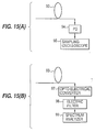
- FIG. 15(A) is a diagram illustrating an example of detectors 75 and 80.
- the wavelength dispersion of an optical fiber 93 is obtained by directly reading the pulse interval between optical pulses.
- the optical pulses transmitted through optical fiber 93 are detected by a photodiode 94.
- the detection result of photodiode 94 is output to a sampling oscilloscope 95 to read the pulse interval of optical pulses 415 and 416.
- FIG. 15(B) is a diagram illustrating an additional example of detectors 75 and 80.
- the wavelength dispersion of an optical fiber 96 is obtained by measuring the frequency element based on the pulse interval between optical pulses.
- the optical pulses transmitted through optical fiber 93 are converted into an electric signal by an opto-electrical converter 97.
- a spectrum analyzer 99 analyzes the frequency to compute the wavelength dispersion of the optical fiber.
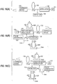
- FIGS. 16(A), 16(B) and 16(C) are diagrams illustrating examples of a dispersion measurement apparatus, according to an embodiment of the present invention, wherein the precision of the dispersion measurement is improved by transmitting an optical pulse and then returning it.
- laser light emitted from a laser diode 101 is modulated by a modulator 102 and transmitted through an optical fiber 104.
- the light transmitted through optical fiber 104 is reflected by a loopback device 105, and input to a detector 103 after being transmitted through optical fiber 104 again.
- the measured amount of dispersion generated through optical fiber 104 can be doubled by reflecting the light by loopback device 105 and transmitting and returning the light through optical fiber 104.
- the dispersion can be detected with high precision even if optical fiber 104 is short or the dispersion of optical fiber 104 is small.
- a laser diode 106, a Mach-Zehnder modulator 107, a pulse generator 108, and a detector 109 are provided on the transmission side of the optical transmission system.
- Laser light emitted from laser diode 106 is input to Mach-Zehnder modulator 107 and, simultaneously, a pulse signal 421 generated by pulse generator 108 is input to Mach-Zehnder modulator 107.
- pulse generator 108 drives Mach-Zehnder modulator 107 on one side only, and sets the driving voltage Vin to double the half-wavelength voltage V ⁇ .
- two optical pulses 422 and 423 are output from Mach-Zehnder modulator 107, and a wavelength chirping is generated corresponding to the increment ratio of pulse signal 421, thereby producing the different wavelengths of optical pulses 422 and 423 output from Mach-Zehnder modulator 107.
- Optical pulses 422 and 423 output from Mach-Zehnder modulator 107 are transmitted through an optical fiber 110, reflected by a loopback device 111 and returned to optical fiber 110. Thus, the pulses are transmitted and returned through optical fiber 110.
- Optical pulses 422' and 423' transmitted and returned through optical fiber 110 are detected by detector 109. The change of the pulse interval between optical pulses 422' and 423' is double the change of the pulse interval measured when the pulses pass through optical fiber 110 only once.
- the pulse interval d + 2 ⁇ d of optical pulses 422' and 423' is measured and compared with the pulse interval d of optical pulses 422 and 423 to compute the change 2 ⁇ d of the pulse interval.
- the wavelength dispersion of optical fiber 110 can be obtained by Equation (12) based on the change 2 ⁇ d of the pulse interval.
- High-precision measurement can be realized even if a dispersion value of optical fiber 110 and wavelength chirping ⁇ are small.
- Laser diode 106, Mach-Zehnder modulator 107, pulse generator 108, and detector 109 can be provided on the transmission side of the optical transmission system by looping back optical pulses 422 and 423 by loopback device 111. As a result, a system configuration of a small size can be realized.
- a laser diode 112 a Mach-Zehnder modulator 113, a pulse generator 114, and a detector 115 are provided on the receiving side of the optical transmission system.
- Laser light emitted from laser diode 112 is input to Mach-Zehnder modulator 113 and, simultaneously, a pulse signal 424 generated by pulse generator 114 is input to Mach-Zehnder modulator 113.
- pulse generator 114 drives Mach-Zehnder modulator 113 on one side only, and sets the driving voltage Vin to double the half-wavelength voltage V ⁇ .
- two optical pulses 425 and 426 are output from Mach-Zehnder modulator 113, and a wavelength chirping is generated corresponding to the increment ratio of pulse signal 424, thereby producing the different wavelengths of optical pulses 425 and 426 output from Mach-Zehnder modulator 113.
- Optical pulses 425 and 426 output from Mach-Zehnder modulator 113 are transmitted through an optical fiber 116, reflected by a loopback device 117 and returned to optical fiber 116. Thus, the pulses are transmitted and returned through optical fiber 116.
- Optical pulses 425' and 426' transmitted and returned through the optical fiber 116 are detected by detector 115.
- the change of the pulse interval of optical pulses 425' and 426' is double the change of the pulse interval measured when the pulses pass through optical fiber 116 only once.
- the pulse interval d + 2 ⁇ d of optical pulses 425' and 426' is measured and compared with the pulse interval d of optical pulses 425 and 426 to compute the change 2 ⁇ d of the pulse interval.
- the wavelength dispersion of optical fiber 116 can be obtained by Equation (12) based on the change 2 ⁇ d of the pulse interval. High-precision measurement can be realized even if a dispersion value of optical fiber 116 and wavelength chirping ⁇ are small.
- optical pulse 432' having a wavelength ⁇ - ⁇ and optical pulse 433' having a wavelength ⁇ + ⁇ are extracted through an optical filter 127 from among optical pulse 432' having a wavelength ⁇ - ⁇ , optical pulse 433' having a wavelength ⁇ + ⁇ , and optical pulse 434' having a wavelength ⁇ transmitted through optical fiber 126.
- the extracted pulses are transmitted to a detector 128.
- Detector 128 detects optical pulses 432' and 433', measures the pulse interval d + ⁇ d of optical pulses 432' and 433', compares the pulse interval d of optical pulses 432 and 433 before the transmission, and computes the change ⁇ d of the pulse interval.
- the wavelength dispersion of optical fiber 126 is obtained by Equation (12) based on the change ⁇ d of the pulse interval.
- FIG. 18(A) is a diagram illustrating a dispersion measurement apparatus
- FIG. 18(B) is a diagram illustrating the extraction of a measurement signal in the dispersion measurement apparatus, according to an embodiment of the present invention.
- the dispersion measurement apparatus in FIGS. 18(A) and 18(B) provides a light source for a main signal separately from a light source for dispersion measurement to reduce the influence of the main signal when performing the dispersion measurement by using one optical wavelength for the main signal and a different wavelength for the dispersion measurement.
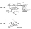
- FIG. 19 is a diagram illustrating a dispersion measurement apparatus, according to a further embodiment of the present invention.
- the dispersion measurement apparatus in FIG. 19 converts a transmitted optical pulse into an electric signal, and obtains the amount of dispersion in a transmission line based on a frequency element of the electric signal.
- an LiNbO 3 modulator is used as a Mach-Zehnder modulator.
- Optical pulses 452 and 453 output from LiNbO 3 modulator 142 are input to an optical fiber 144.
- Optical pulse 452' transmitted through optical fiber 144 can be incorporated into optical pulse 453' by adjusting the time interval between optical pulses 452 and 453. Therefore, assuming that the frequency element of optical pulses 452 and 453 before the transmission is 2f0, the frequency element of optical pulse 453' after the transmission through optical fiber 144 is f0.
- Optical pulse 453' is converted into an electric signal by an opto-electrical converter 145, and a signal of a frequency element 2f0 is extracted through an electric filter 146 and output to a detector 147. Then, the wavelength dispersion of optical fiber 144 can be obtained by reading the time interval d when the detected signal is only a signal of the frequency element f0 and the frequency element 2f0 becomes 0.
- FIGS. 20(A)(1), 20(A)(2), 20(B)(1), 20(B)(2), 20(C)(1) and 20(C)(2) are diagrams illustrating a method of measuring a dispersion value by comparing the spectrum element of a pulse string before and after transmission, according to an embodiment of the present invention.
- optical pulse 463' is incorporated into optical pulse 464', and an optical pulse 464'' is generated.
- the frequency element through optical pulses 462'' and 464'' is f0.
- the amount of dispersion compensation can be set by detecting the frequency element through the optical pulse after the transmission.
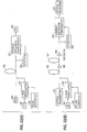
- FIG. 21(A) is a diagram illustrating a dispersion compensation apparatus applied to a transmission system without a repeater, according to an embodiment of the present invention.
- the dispersion compensation apparatus of FIG. 21(A) converts a light output from a single light source into a plurality of optical pulses having different wavelengths, and performs dispersion compensation of a transmission line based on a measured dispersion amount when the optical pulses are transmitted through the transmission line. This method is available when it is necessary to measure the dispersion value of a transmission line when the system is first started.
- two optical pulses are output from LiNbO 3 modulator 152, and a wavelength chirping is generated corresponding to the increment ratio of the pulse signal, thereby producing the different wavelengths of the optical pulses output from LiNbO 3 modulator 152, and thereby easily facilitating dispersion measurement.
- Detector 156 outputs the detection result of the wavelength dispersion to a dispersion compensator 157.
- Dispersion compensator 157 compensates the wavelength dispersion of optical fiber 155 based on the detection result of the wavelength dispersion output from detector 156.
- the wavelength dispersion generated during the transmission through optical fiber 155 can be compensated for by dispersion compensator 157, thereby realizing super-high-speed optical transmission.
- the wavelength dispersion of the 1.3 ⁇ m zero-dispersion single mode fiber can be exactly compensated for by accurately adjusting the length of the dispersion compensation fiber based on the detection result of the wavelength dispersion output from detector 156. Therefore, an optical signal can be correctly transmitted even when there is only a small dispersion compensation tolerance.
- laser light emitted from a laser diode 161 is input to LiNbO 3 modulator 162 and, simultaneously, a pulse signal generated by a pulse generator 163 is input to LiNbO 3 modulator 162.
- pulse generator 163 drives LiNbO 3 modulator 162 on one side only, and sets the driving voltage Vin to double the half-wavelength voltage V ⁇ .
- two optical pulses are output from LiNbO 3 modulator 162, and a wavelength chirping is generated corresponding to the increment ratio of the pulse signal, thereby producing the different wavelengths of the optical pulses output from LiNbO 3 modulator 162, and thereby easily facilitating dispersion measurement.
- the two optical pulses output from LiNbO 3 modulator 162 are input to and transmitted through an optical fiber 165, and then amplified in a repeater 166.
- the optical pulses amplified in repeater 166 are input to and transmitted through an optical fiber 167, and then amplified in a repeater 168.
- the optical pulses amplified by repeater 168 are detected by a detector 169.
- the pulse interval d + ⁇ d between the optical pulses after the transmission through optical fibers 165 and 167 is measured, and compared with the pulse interval d of the optical pulses before the transmission through optical fibers 165 and 167 in order to compute the change ⁇ d of the pulse interval.
- the wavelength dispersion of optical fibers 165 and 167 is obtained by Equation (12) based on the change ⁇ d of the pulse interval.
- Detector 169 outputs the detection result of the wavelength dispersion to a dispersion compensator 170.
- Dispersion compensator 170 compensates the wavelength dispersion of optical fibers 165 and 167 based on the detection result of the wavelength dispersion output from detector 169.
- any loss caused during the transmission through optical fibers 165 and 167 can be compensated by repeaters 166 and 168, and the wavelength dispersion generated during the transmission through optical fibers 165 and 167 can be compensated by dispersion compensator 170, thereby realizing super-high-speed and long-distance optical transmission.
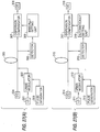
- FIG. 22(A) is a diagram illustrating a dispersion compensation apparatus applied to a transmission system without a repeater, according to an embodiment of the present invention.
- the dispersion compensation apparatus illustrated in FIG. 22(A) converts a light output from a single light source into a plurality of optical pulses having different wavelengths, and dynamically performs dispersion compensation of a transmission line based on a dispersion amount when the optical pulses are transmitted through the transmission line.
- This method is not only available when it is necessary to measure the dispersion value of a transmission line when the system is started, but also applicable when it is necessary to constantly monitor a dispersion value during operation, and to appropriately set the amount of dispersion compensation
- laser light emitted from a laser diode 181 is input to LiNbO 3 modulator 182 and, simultaneously, a pulse signal generated by a pulse generator 183 is input to LiNbO 3 modulator 182.
- pulse generator 183 drives LiNbO 3 modulator 182 on one side only, and sets the driving voltage Vin to double the half-wavelength voltage V ⁇ .
- the two optical pulses output from LiNbO 3 modulator 182 are input to an optical fiber 185, and the optical pulse obtained through optical fiber 185 is detected by a detector 186.
- the pulse interval d + ⁇ d between the optical pulses after the transmission through optical fiber 185 is measured, and compared with the pulse interval d of the optical pulses before the transmission through optical fiber 185 in order to compute the change ⁇ d of the pulse interval.
- the wavelength dispersion of optical fiber 185 is obtained by Equation (12) based on the change ⁇ d of the pulse interval.
- the two optical pulses output from LiNbO 3 modulator 192 are input to and transmitted through an optical fiber 195, and then amplified in a repeater 196.
- the optical pulses amplified in repeater 196 are input to and transmitted through an optical fiber 197, and then amplified by repeater 198.
- the optical pulses amplified by repeater 198 are detected by a detector 199.
- the pulse interval d + ⁇ d between the optical pulses after the transmission through optical fibers 195 and 197 is measured, and compared with the pulse interval d of the optical pulses before the transmission through optical fibers 195 and 197 in order to compute the change ⁇ d of the pulse interval.
- the wavelength dispersion of optical fibers 195 and 197 is obtained by Equation (12) based on the change ⁇ d of the pulse interval.
- Detector 199 outputs the detection result of the wavelength dispersion to a variable dispersion compensator 200.
- Variable dispersion compensator 200 compensates in real time the wavelength dispersion of optical fibers 195 and 197 based on the detection result of the wavelength dispersion output from detector 199. When the pulse intervals before and after the transmission match each other, the dispersion of optical fibers 195 and 197 is completely compensated for.
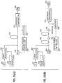
- FIG. 24(A) is a diagram illustrating a dispersion compensation apparatus applied to a transmission system without a repeater, according to an embodiment of the present invention.
- the dispersion compensation apparatus in FIG. 24(A) compensates the wavelength dispersion of a main signal light by changing the wavelength of the main signal light based on the amount of dispersion in a transmission line.
- laser light emitted from a laser diode 231 is input to LiNbO 3 modulator 232 and, simultaneously, a pulse signal generated by a pulse generator 233 is input to LiNbO 3 modulator 232.
- pulse generator 233 drives LiNbO 3 modulator 232 on one side only, and sets the driving voltage Vin to double the half-wavelength voltage V ⁇ .
- Detector 239 outputs the wavelength dispersion detection result to a wavelength control unit 242.
- Wavelength control unit 242 changes the wavelength of a laser light output from a main signal generation unit 234 according to the wavelength dispersion detection result output from detector 239, and compensates the wavelength dispersion of optical fibers 235 and 237.
- the amount of wavelength change ⁇ ' (nm) of the laser light output from main signal generation unit 234 is computed by Equation (13).
- main signal generation unit 234 when a main signal output from main signal generation unit 234 is transmitted through optical fibers 235 and 237 to a main signal detection unit 241, the loss caused during the transmission can be compensated for by repeaters 236 and 238, and the wavelength dispersion generated during the transmission can be compensated for, thereby realizing a super-high-speed and long-distance optical transmission.
- the dispersion compensation of optical fibers 235 and 237 can be performed with high precision by providing a dispersion compensator 240 in a transmission line, approximately performing the dispersion compensation of optical fibers 235 and 237 through dispersion compensator 240, and changing the wavelength of the laser light output from main signal generation unit 234.
- laser light emitted from a laser diode 251 is input to LiNbO 3 modulator 252 and, simultaneously, a pulse signal generated by a pulse generator 253 is input to LiNbO 3 modulator 252.
- pulse generator 253 drives LiNbO 3 modulator 252 on one side only, and sets the driving voltage Vin to double the half-wavelength voltage V ⁇ .
- Detector 256 outputs the wavelength dispersion detection result to a optical power control unit 259.
- Optical power control unit 259 changes the optical power of a laser light output from a main signal generation unit 254 according to the wavelength dispersion detection result output from detector 256, and compensates for the wavelength dispersion of optical fiber 255.
- Nonlinearity generated depending on the intensity of the optical input power to optical fiber 255 is adopted to compensate for the wavelength dispersion by changing an optical power of a laser light. Through this nonlinearity, an optical pulse passing through optical fiber 255 is subject to compression or expansion. Therefore, the influence of the dispersion of a main signal light can be adjusted by changing an optical output power.
- Optical pulse 473' is converted into an electric signal by an opto-electrical converter 287, and a signal of a frequency element 2f0 is extracted through an electric filter 288 and output to a detector 289. Then, the wavelength dispersion of optical fiber 285 can be obtained by reading the time interval d when the detected signal is only a signal of the frequency element f0 and the frequency element 2f0 becomes 0.
- laser light emitted from a laser diode 311 is input to LiNbO 3 modulator 312 and, simultaneously, a pulse signal generated by a pulse generator 313 is input to LiNbO 3 modulator 312.
- pulse generator 313 drives LiNbO 3 modulator 312 on one side only, and sets the driving voltage Vin to double the half-wavelength voltage V ⁇ .
- the wavelength dispersion generated during the transmission through optical fiber 315 can be compensated for by dispersion compensator 317 in real time, thereby stably realizing a super-high-speed transmission. Furthermore, using a CPU, etc, system management of such as the measurement of a dispersion value, the setting of dispersion compensation, etc. can be performed.
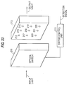
- laser light having a wavelength ⁇ emitted from a laser diode 331 is input to a Mach-Zehnder modulator 332 and, simultaneously, a pulse signal 481 generated by a pulse generator 333 is input to Mach-Zehnder modulator 332.
- pulse generator 333 drives Mach-Zehnder modulator 332 on one side only, and sets the driving voltage Vin to double the half-wavelength voltage V ⁇ .
- an LiNbO 3 modulator allows the external modulation to be efficiently performed.
- a semiconductor modulator allows a laser diode and the Mach-Zehnder modulator to be easily integrated. Therefore, a dispersion measurement apparatus can be smaller and lighter-weight.
- a plurality of optical pulses can be output by modulating a split light at a voltage exceeding a half-wavelength voltage, and a wavelength chirping can be generated corresponding to the increment ratio of the voltage input from the drive signal input unit. Also, a voltage exceeding a half-wavelength voltage can be input to one electrode to modulate the phase of the split light at different modulation efficiencies. Thus, a single light source can generate a plurality of optical pulses having different wavelengths.
- a plurality of light pulses having different wavelengths can be input from the transmission or receiving side of a transmission line, and the transmitted light pulses are detected on the receiving or transmission side of the transmission line.
- optical pulses can be easily input to a transmission line without having any influence on a main signal transmitted through the transmission line, and can also be easily retrieved from the transmission line after the transmission.
- a dispersion compensation unit is provided on the transmission or receiving side of a transmission line or in a repeater.
- an optical pulse generation apparatus, a detection apparatus, and a dispersion compensation unit can be positioned at the same point, thereby facilitating the design of the optical pulse generation apparatus, the detection apparatus, and the dispersion compensation unit as a single structure, and realizing a compact configuration for a dispersion measurement system.
- an amount of dispersion compensation can be variable.
- dispersion compensation in a transmission line can be performed with high precision not only when a dispersion value for a transmission line is computed when a system is started, but also when a dispersion value for the transmission line is measured in real time while the transmission line is being used.
- the optical transmission can be performed at a higher speed.
- the wavelength of a main signal is changed depending on the amount of dispersion in a transmission line. Therefore, the dispersion compensation can be performed in the transmission line only by adjusting the wavelength of a light source. As a result, the number of units required when the dispersion compensation is performed can be reduced, thereby realizing a smaller, lighter-weight and inexpensive dispersion compensation system.
- the output power of a main signal light can be varied depending on the amount of dispersion in a transmission line. Since the optical pulses transmitted through a transmission line can be compressed of extended based on the nonlinearity of the output power of the main signal light, the influence of the dispersion on the light of the main signal can be reduced.
- dispersion compensation in a transmission line is performed in such a way that the frequency elements before and after transmission match each other. As a result, the dispersion compensation in the transmission line can be easily realized.
- an optical modulation unit increases/decreases optical output with an increasing driving voltage.
- only increasing a driving voltage causes an optical pulse to be output.
- only decreasing a driving voltage also causes an optical pulse to be output.
- a modulator is a Mach-Zehnder LiNbO 3 modulator. This allows a laser diode and the Mach-Zehnder modulator to be easily integrated, and a light source can be incorporated into the Mach-Zehnder modulator. Therefore, a dispersion measurement apparatus can become smaller and lighter-weight.
- an optical filter separates a plurality of optical pulses having different wavelengths. This allows a short optical pulse having a single wavelength to be output from a system with a simple configuration, thereby easily generating an optical source for a super-high-speed optical transmission.
- the wavelength of the light for a main signal is different from the wavelength of the light for dispersion measurement.
- the light of the main signal can be easily removed using an optical filter even when the light of the main signal is detected during the dispersion measuring process, thereby allowing the light for the dispersion measurement to be solely extracted.
- a dispersion compensation unit is positioned on the transmission or receiving side of the transmission line or in a repeater.
- an optical pulse generation apparatus, a detection apparatus, and a dispersion compensation unit can be positioned at the same point, thereby facilitating the design of an optical pulse generation apparatus, the detection apparatus, and the dispersion compensation unit as a single structure, and realizing a compact configuration for a dispersion measurement system.
- an amount of dispersion compensation can be manually or automatically varied.
- the dispersion compensation in a transmission line can be periodically performed.
- the dispersion compensation in the transmission line can be performed in real time with high precision.
- the wavelength of a main signal is changed depending on the amount of dispersion in a transmission line. Therefore, the amount of dispersion in the transmission line can be varied, and the dispersion compensation can be performed in the transmission line only by adjusting the wavelength of a light source. As a result, the number of units required when the dispersion compensation is performed can be reduced, thereby realizing a smaller, lighter-weight and inexpensive dispersion compensation system.
- the output power of a main signal light can be varied depending on the amount of dispersion in a transmission line. Since the optical pulse transmitted through a transmission line can be compressed or extended based on the nonlinearity of the output power of the main signal light, the influence of the dispersion on the light of the main signal can be reduced.
- optical pulses can be generated at predetermined intervals based on electric pulses of a predetermined frequency.
- the generated optical pulses are transmitted through a transmission line, and the transmitted optical pulses are converted into electric signals.
- the dispersion compensation in the transmission line is performed in such a way that the frequency elements of the electric signals can refer to the predetermined frequency.
- the dispersion compensation in a transmission line can be easily realized.
Landscapes
- Physics & Mathematics (AREA)
- Engineering & Computer Science (AREA)
- Electromagnetism (AREA)
- Computer Networks & Wireless Communication (AREA)
- Signal Processing (AREA)
- Nonlinear Science (AREA)
- Ceramic Engineering (AREA)
- Crystallography & Structural Chemistry (AREA)
- Chemical & Material Sciences (AREA)
- General Physics & Mathematics (AREA)
- Optics & Photonics (AREA)
- Optical Modulation, Optical Deflection, Nonlinear Optics, Optical Demodulation, Optical Logic Elements (AREA)
- Optical Communication System (AREA)
Applications Claiming Priority (3)
| Application Number | Priority Date | Filing Date | Title |
|---|---|---|---|
| JP232011/97 | 1997-08-28 | ||
| JP23201197A JP3913856B2 (ja) | 1997-08-28 | 1997-08-28 | 光パルス生成装置、分散測定装置、分散補償装置及び分散測定方法 |
| JP23201197 | 1997-08-28 |
Publications (2)
| Publication Number | Publication Date |
|---|---|
| EP0899602A2 true EP0899602A2 (fr) | 1999-03-03 |
| EP0899602A3 EP0899602A3 (fr) | 2000-07-19 |
Family
ID=16932562
Family Applications (1)
| Application Number | Title | Priority Date | Filing Date |
|---|---|---|---|
| EP98105842A Withdrawn EP0899602A3 (fr) | 1997-08-28 | 1998-03-31 | Procédé et dispositif de commande d'un modulateur optique, pour mesurer et compenser la dispersion dans une ligne de transmission optique |
Country Status (3)
| Country | Link |
|---|---|
| US (3) | US5973816A (fr) |
| EP (1) | EP0899602A3 (fr) |
| JP (1) | JP3913856B2 (fr) |
Cited By (5)
| Publication number | Priority date | Publication date | Assignee | Title |
|---|---|---|---|---|
| WO2003058312A3 (fr) * | 2001-12-31 | 2003-10-16 | 3M Innovative Properties Co | Systeme de compensation de dispersion d'ordre eleve avec modulation de phase |
| US6829409B2 (en) | 2001-12-31 | 2004-12-07 | 3M Innovative Properties Company | Method for higher-order dispersion compensation |
| US7016567B2 (en) | 2001-12-31 | 2006-03-21 | 3M Innovative Properties Company | System for higher-order dispersion compensation including a delay line |
| US7062123B2 (en) | 2001-12-31 | 2006-06-13 | 3M Innovative Properties Company | System for higher-order dispersion compensation |
| CN104764592A (zh) * | 2015-04-08 | 2015-07-08 | 电子科技大学 | 一种电光强度调制器啁啾参数的测量方法 |
Families Citing this family (39)
| Publication number | Priority date | Publication date | Assignee | Title |
|---|---|---|---|---|
| JP3649556B2 (ja) * | 1997-08-20 | 2005-05-18 | 富士通株式会社 | 波長分散制御のための方法と装置及び分散量検出方法 |
| JP3913856B2 (ja) * | 1997-08-28 | 2007-05-09 | 富士通株式会社 | 光パルス生成装置、分散測定装置、分散補償装置及び分散測定方法 |
| WO1999028723A1 (fr) * | 1997-11-28 | 1999-06-10 | Fujitsu Limited | Procede de mesure de la dispersion en mode de polarisation, dispositif de commande de compensation de dispersion et procede de commande de compensation de dispersion |
| KR100438814B1 (ko) * | 1998-01-31 | 2004-07-16 | 삼성전자주식회사 | 분산보상광섬유모듈을 이용한 광변조기의 처핑값 측정 장치 |
| US6370283B1 (en) * | 1998-10-29 | 2002-04-09 | Tycom (U.S.) Inc. | Electro-optic modulator for generating solitons |
| US6266170B1 (en) * | 1999-06-22 | 2001-07-24 | Avanex Corporation | Method and system for compensating for chromatic dispersion in an optical network |
| JP3631653B2 (ja) * | 2000-02-21 | 2005-03-23 | 独立行政法人科学技術振興機構 | 群速度分散測定装置および群速度分散測定方法 |
| FR2806559B1 (fr) * | 2000-03-20 | 2002-05-31 | Cit Alcatel | Regenerateur optique synchrone par modulation d'intensite et modulation de phase par effet kerr croise |
| AU2002213589A1 (en) * | 2000-03-22 | 2001-12-17 | University Of Maryland Baltimore County | System and method for reducing differential mode dispersion effects in multimode optical fiber transmissions |
| JP2001356075A (ja) * | 2000-06-15 | 2001-12-26 | Advantest Corp | 光特性測定装置、方法、記録媒体 |
| US6330381B1 (en) * | 2000-06-30 | 2001-12-11 | Nortel Networks Limited | Methods, systems, media and signals for determining optimum pre-compensation and optimization of an optical system |
| JP4592887B2 (ja) * | 2000-08-07 | 2010-12-08 | 富士通株式会社 | 波長分散を補償する方法及びシステム |
| WO2002025783A2 (fr) * | 2000-09-22 | 2002-03-28 | Calmar Optcom, Inc. | Laser a fibre a blocage actif de mode avec sortie a frequence modulee |
| US7139478B2 (en) * | 2001-03-15 | 2006-11-21 | Fitel Usa Corp. | Nonlinear device comprising a spectrally broadening fiber |
| US6839363B2 (en) * | 2001-03-16 | 2005-01-04 | Calmar Optcom, Inc. | Digital control of actively mode-locked lasers |
| US6845108B1 (en) | 2001-05-14 | 2005-01-18 | Calmar Optcom, Inc. | Tuning of laser wavelength in actively mode-locked lasers |
| JP4608149B2 (ja) * | 2001-08-10 | 2011-01-05 | 住友大阪セメント株式会社 | マッハツェンダ型光変調器の半波長電圧測定方法及び装置 |
| US6614515B2 (en) * | 2001-11-19 | 2003-09-02 | Lasercomm, Inc. | Method and apparatus for dispersion measurement |
| US7577366B2 (en) * | 2002-01-07 | 2009-08-18 | Fujitsu Limited | Selectable dispersion enhancement |
| US6734955B2 (en) * | 2002-01-28 | 2004-05-11 | Mark Stephen Wight | Dispersion measurement in optical networks |
| US20040208523A1 (en) * | 2002-01-30 | 2004-10-21 | Tellabs Operations, Inc. | Swept frequency reflectometry using an optical signal with sinusoidal modulation |
| JP3892326B2 (ja) | 2002-03-26 | 2007-03-14 | 富士通株式会社 | 光変調器の制御装置 |
| JP3881270B2 (ja) * | 2002-03-26 | 2007-02-14 | 富士通株式会社 | 光変調器の駆動制御装置および駆動制御方法 |
| JP3975810B2 (ja) * | 2002-04-05 | 2007-09-12 | 株式会社日立製作所 | 光片側サイドバンド送信器 |
| JP4047099B2 (ja) * | 2002-08-20 | 2008-02-13 | 富士通株式会社 | 時分割多重信号光の分離装置、並びに、それを用いた光受信装置および光伝送システム |
| US6721081B1 (en) * | 2002-09-26 | 2004-04-13 | Corning Incorporated | Variable duty cycle optical pulses |
| JP4082992B2 (ja) * | 2002-11-21 | 2008-04-30 | 富士通株式会社 | 光分散モニタ装置および方法、並びに、それを用いた光伝送システム |
| JP4149298B2 (ja) | 2003-03-27 | 2008-09-10 | 富士通株式会社 | 光変調器の制御装置 |
| JP4459547B2 (ja) * | 2003-04-15 | 2010-04-28 | 独立行政法人科学技術振興機構 | 光パルス圧縮器および光関数発生器、光パルス圧縮方法および光関数発生方法 |
| JP4789460B2 (ja) * | 2004-12-22 | 2011-10-12 | 株式会社アドバンテスト | 光スイッチ及び光試験装置 |
| US7336365B2 (en) * | 2005-02-11 | 2008-02-26 | Optoplan As | Method and apparatus for suppression of crosstalk and noise in time-division multiplexed interferometric sensor systems |
| JP2007114307A (ja) * | 2005-10-18 | 2007-05-10 | Fujitsu Ltd | チャープ切り替え回路及び光伝送システム |
| WO2008023480A1 (fr) * | 2006-08-21 | 2008-02-28 | Nec Corporation | Modulateur et procédé de modulation de lumière mach-zehnder, émetteur, modulateur, appareil d'émission et appareil de réception de lumière |
| JP2009302703A (ja) * | 2008-06-11 | 2009-12-24 | Toshiba Corp | コンプリメンタリー光配線システム |
| JP5471578B2 (ja) * | 2010-02-23 | 2014-04-16 | 富士通株式会社 | 波長分散測定方法および装置、並びに、光伝送システム |
| JP5594192B2 (ja) * | 2011-03-08 | 2014-09-24 | 住友大阪セメント株式会社 | 光変調器 |
| JP6031963B2 (ja) * | 2012-11-21 | 2016-11-24 | 富士通株式会社 | 光送信装置、光送信方法、および光送信プログラム |
| TWI656704B (zh) * | 2014-02-18 | 2019-04-11 | 日商尼康股份有限公司 | Method for generating pulsed light, pulsed laser device, and exposure device and inspection device having the same |
| US10931376B2 (en) | 2019-04-30 | 2021-02-23 | At&T Intellectual Property I, L.P. | Enhancement of optical communications and optical fiber performance |
Family Cites Families (16)
| Publication number | Priority date | Publication date | Assignee | Title |
|---|---|---|---|---|
| JPS6165131A (ja) * | 1984-09-06 | 1986-04-03 | Fujitsu Ltd | 光フアイバ波長分散係数測定装置 |
| JPS633236A (ja) * | 1986-06-24 | 1988-01-08 | Fujikura Ltd | 光フアイバの波長分散測定器 |
| US4752125A (en) * | 1986-12-19 | 1988-06-21 | Siecor Corporation | Apparatus to measure fiber dispersion |
| CA2011954C (fr) * | 1989-03-14 | 1994-02-22 | Fujitsu Limited | Modulateur optique |
| JP2679223B2 (ja) * | 1989-03-14 | 1997-11-19 | 富士通株式会社 | 光変調方法及び光変調器 |
| CA2083219C (fr) * | 1991-11-19 | 1999-01-05 | Hiroshi Nishimoto | Emetteur optique muni d'un modulateur optique |
| JPH06209293A (ja) * | 1992-07-31 | 1994-07-26 | American Teleph & Telegr Co <Att> | 光伝送システムにおける変調装置 |
| FR2696874B1 (fr) * | 1992-10-13 | 1994-12-09 | Thomson Csf | Modulateur d'onde électromagnétique à puits quantiques. |
| FR2699295B1 (fr) * | 1992-12-15 | 1995-01-06 | Thomson Csf | Dispositif de traitement optique de signaux électriques. |
| WO1994028455A1 (fr) * | 1993-06-01 | 1994-12-08 | United Technologies Corporation | Modulateur electro-optique dote d'un systeme de regulation de polarisation a activation par porte |
| US5625722A (en) * | 1994-12-21 | 1997-04-29 | Lucent Technologies Inc. | Method and apparatus for generating data encoded pulses in return-to-zero format |
| JP3432957B2 (ja) * | 1995-07-05 | 2003-08-04 | 三洋電機株式会社 | 光変調装置および光ファイバ通信システム |
| US5644665A (en) * | 1995-07-27 | 1997-07-01 | The United States Of America As Represented By The Secretary Of The Navy | Multi-octave, high dynamic range operation of low-biased modulators by balanced detection |
| JP4086912B2 (ja) * | 1995-09-11 | 2008-05-14 | 富士通株式会社 | 光変調器の制御装置 |
| US5835212A (en) * | 1996-10-18 | 1998-11-10 | Uniphase Telecommunications Products, Inc. | Variable chirp optical modulator using single modulation source |
| JP3913856B2 (ja) * | 1997-08-28 | 2007-05-09 | 富士通株式会社 | 光パルス生成装置、分散測定装置、分散補償装置及び分散測定方法 |
-
1997
- 1997-08-28 JP JP23201197A patent/JP3913856B2/ja not_active Expired - Fee Related
-
1998
- 1998-03-20 US US09/045,121 patent/US5973816A/en not_active Expired - Lifetime
- 1998-03-31 EP EP98105842A patent/EP0899602A3/fr not_active Withdrawn
-
1999
- 1999-02-08 US US09/245,920 patent/US5982530A/en not_active Expired - Lifetime
- 1999-02-25 US US09/257,497 patent/US6262828B1/en not_active Expired - Lifetime
Cited By (7)
| Publication number | Priority date | Publication date | Assignee | Title |
|---|---|---|---|---|
| WO2003058312A3 (fr) * | 2001-12-31 | 2003-10-16 | 3M Innovative Properties Co | Systeme de compensation de dispersion d'ordre eleve avec modulation de phase |
| US6829409B2 (en) | 2001-12-31 | 2004-12-07 | 3M Innovative Properties Company | Method for higher-order dispersion compensation |
| US7013063B2 (en) | 2001-12-31 | 2006-03-14 | 3M Innovative Properties Company | System for higher-order dispersion compensation including phase modulation |
| US7016567B2 (en) | 2001-12-31 | 2006-03-21 | 3M Innovative Properties Company | System for higher-order dispersion compensation including a delay line |
| US7062123B2 (en) | 2001-12-31 | 2006-06-13 | 3M Innovative Properties Company | System for higher-order dispersion compensation |
| CN104764592A (zh) * | 2015-04-08 | 2015-07-08 | 电子科技大学 | 一种电光强度调制器啁啾参数的测量方法 |
| CN104764592B (zh) * | 2015-04-08 | 2017-08-08 | 电子科技大学 | 一种电光强度调制器啁啾参数的测量方法 |
Also Published As
| Publication number | Publication date |
|---|---|
| JP3913856B2 (ja) | 2007-05-09 |
| JPH1172761A (ja) | 1999-03-16 |
| US5982530A (en) | 1999-11-09 |
| EP0899602A3 (fr) | 2000-07-19 |
| US6262828B1 (en) | 2001-07-17 |
| US5973816A (en) | 1999-10-26 |
Similar Documents
| Publication | Publication Date | Title |
|---|---|---|
| US5982530A (en) | Apparatus for driving an optical modulator to measure, and compensate for, dispersion in an optical transmission line | |
| EP1443689B1 (fr) | Réduction au minimum de la dispersion de lignes de transmission optiques | |
| US7489880B2 (en) | Apparatus and method for measuring the dispersion of a fiber span | |
| US6661974B1 (en) | Optical transmitter and optical transmission system | |
| EP1536259B1 (fr) | Système de transmission optique, de multiplexage optique et techniques associées | |
| EP1335509B1 (fr) | Circuit de transmission optique | |
| JPH0799478A (ja) | ファイバオプティック送信システムの分散補償装置と方法 | |
| US6122086A (en) | Compensation of dispersion | |
| US20020018213A1 (en) | Wavelength dispersion measuring device and a method thereof | |
| US6510255B2 (en) | Optical transmission apparatus | |
| US6304348B1 (en) | Optical communication method and optical communication system based on optical phase conjugation | |
| US5619320A (en) | Method and apparatus for measuring dispersion zero along an optical fiber | |
| EP1385281B1 (fr) | Méthode et dispositif de surveillance de dispersion, et méthode et dispositif pour compenser la dépendance en température de la pente de dispersion | |
| US6674936B2 (en) | Polarization mode dispersion compensation using a wavelength locked loop | |
| EP1309115B1 (fr) | Procédé de mesure du chirp | |
| US5852700A (en) | Method and device for the generation of ultrashort optical pulses | |
| Campillo et al. | Phase performance of an eight-channel wavelength-division-multiplexed analog-delay line | |
| EP1387158A2 (fr) | Méthode de retardation d'un balayage de mono-phase et appareil de mesure de dispersion à dépendance chromatique et de polarisation. | |
| US6323992B1 (en) | Wavelength converter and wavelength conversion method | |
| JP4437994B2 (ja) | 光伝送装置及び光伝送方法 | |
| JP2001244896A (ja) | 光送信装置 |
Legal Events
| Date | Code | Title | Description |
|---|---|---|---|
| PUAI | Public reference made under article 153(3) epc to a published international application that has entered the european phase |
Free format text: ORIGINAL CODE: 0009012 |
|
| AK | Designated contracting states |
Kind code of ref document: A2 Designated state(s): DE FR GB |
|
| AX | Request for extension of the european patent |
Free format text: AL;LT;LV;MK;RO;SI |
|
| PUAL | Search report despatched |
Free format text: ORIGINAL CODE: 0009013 |
|
| 17P | Request for examination filed |
Effective date: 20000425 |
|
| RIC1 | Information provided on ipc code assigned before grant |
Free format text: 7G 02F 1/03 A, 7H 04B 10/18 B, 7G 01M 11/00 B |
|
| AK | Designated contracting states |
Kind code of ref document: A3 Designated state(s): AT BE CH DE DK ES FI FR GB GR IE IT LI LU MC NL PT SE |
|
| AX | Request for extension of the european patent |
Free format text: AL;LT;LV;MK;RO;SI |
|
| AKX | Designation fees paid |
Free format text: DE FR GB |
|
| RTI1 | Title (correction) |
Free format text: METHOD AND APPARATUS OF MEASURING, AND COMPENSATE FOR, DISPERSION IN AN OPTICAL TRANSMISSION LINE |
|
| GRAP | Despatch of communication of intention to grant a patent |
Free format text: ORIGINAL CODE: EPIDOSNIGR1 |
|
| STAA | Information on the status of an ep patent application or granted ep patent |
Free format text: STATUS: THE APPLICATION IS DEEMED TO BE WITHDRAWN |
|
| 18D | Application deemed to be withdrawn |
Effective date: 20070210 |