EP0899631A2 - Elektrostatisches Aufzeichnungsgerät und Reinigungsklinge - Google Patents
Elektrostatisches Aufzeichnungsgerät und Reinigungsklinge Download PDFInfo
- Publication number
- EP0899631A2 EP0899631A2 EP98116086A EP98116086A EP0899631A2 EP 0899631 A2 EP0899631 A2 EP 0899631A2 EP 98116086 A EP98116086 A EP 98116086A EP 98116086 A EP98116086 A EP 98116086A EP 0899631 A2 EP0899631 A2 EP 0899631A2
- Authority
- EP
- European Patent Office
- Prior art keywords
- cleaning blade
- edge
- recording apparatus
- image
- electrostatic recording
- Prior art date
- Legal status (The legal status is an assumption and is not a legal conclusion. Google has not performed a legal analysis and makes no representation as to the accuracy of the status listed.)
- Withdrawn
Links
- 238000004140 cleaning Methods 0.000 title claims abstract description 141
- 239000013013 elastic material Substances 0.000 claims abstract 3
- 108091008695 photoreceptors Proteins 0.000 description 41
- 238000010438 heat treatment Methods 0.000 description 15
- 238000010586 diagram Methods 0.000 description 14
- 238000012545 processing Methods 0.000 description 14
- 230000002159 abnormal effect Effects 0.000 description 13
- 238000012546 transfer Methods 0.000 description 10
- 239000000314 lubricant Substances 0.000 description 5
- 230000002411 adverse Effects 0.000 description 4
- 238000005516 engineering process Methods 0.000 description 4
- JOYRKODLDBILNP-UHFFFAOYSA-N Ethyl urethane Chemical compound CCOC(N)=O JOYRKODLDBILNP-UHFFFAOYSA-N 0.000 description 3
- 230000000694 effects Effects 0.000 description 3
- 229920001971 elastomer Polymers 0.000 description 3
- 239000000463 material Substances 0.000 description 3
- 239000002390 adhesive tape Substances 0.000 description 2
- 239000011248 coating agent Substances 0.000 description 2
- 238000000576 coating method Methods 0.000 description 2
- 238000011156 evaluation Methods 0.000 description 2
- 238000004299 exfoliation Methods 0.000 description 2
- 238000011086 high cleaning Methods 0.000 description 2
- 238000004519 manufacturing process Methods 0.000 description 2
- 238000002844 melting Methods 0.000 description 2
- 230000008018 melting Effects 0.000 description 2
- 239000002245 particle Substances 0.000 description 2
- 229920000642 polymer Polymers 0.000 description 2
- 238000003825 pressing Methods 0.000 description 2
- 238000012360 testing method Methods 0.000 description 2
- 101100065878 Caenorhabditis elegans sec-10 gene Proteins 0.000 description 1
- 101100172879 Caenorhabditis elegans sec-5 gene Proteins 0.000 description 1
- 239000004809 Teflon Substances 0.000 description 1
- 229920006362 Teflon® Polymers 0.000 description 1
- 229920006311 Urethane elastomer Polymers 0.000 description 1
- 238000013459 approach Methods 0.000 description 1
- 239000003795 chemical substances by application Substances 0.000 description 1
- 238000011109 contamination Methods 0.000 description 1
- 238000011161 development Methods 0.000 description 1
- 238000009826 distribution Methods 0.000 description 1
- 239000000428 dust Substances 0.000 description 1
- 230000002708 enhancing effect Effects 0.000 description 1
- 230000001050 lubricating effect Effects 0.000 description 1
- 238000005259 measurement Methods 0.000 description 1
- 239000000203 mixture Substances 0.000 description 1
- 239000000843 powder Substances 0.000 description 1
- 230000000630 rising effect Effects 0.000 description 1
- 238000007789 sealing Methods 0.000 description 1
Images


Classifications
-
- G—PHYSICS
- G03—PHOTOGRAPHY; CINEMATOGRAPHY; ANALOGOUS TECHNIQUES USING WAVES OTHER THAN OPTICAL WAVES; ELECTROGRAPHY; HOLOGRAPHY
- G03G—ELECTROGRAPHY; ELECTROPHOTOGRAPHY; MAGNETOGRAPHY
- G03G21/00—Arrangements not provided for by groups G03G13/00 - G03G19/00, e.g. cleaning, elimination of residual charge
- G03G21/0005—Arrangements not provided for by groups G03G13/00 - G03G19/00, e.g. cleaning, elimination of residual charge for removing solid developer or debris from the electrographic recording medium
- G03G21/0011—Arrangements not provided for by groups G03G13/00 - G03G19/00, e.g. cleaning, elimination of residual charge for removing solid developer or debris from the electrographic recording medium using a blade; Details of cleaning blades, e.g. blade shape, layer forming
- G03G21/0017—Details relating to the internal structure or chemical composition of the blades
Definitions
- the present invention relates to an electrostatic recording apparatus wherein an image carrier is cleaned by a cleaning blade, and to a cleaning blade used for the electrostatic recording apparatus.
- an electrostatic image is formed on an image carrier such as an electrophotographic photoreceptor and it is developed to become a toner image, then it is transferred onto a transfer sheet and fixed thereon to become a toner image, while the surface of the image carrier on which image forming has been completed is cleaned by a cleaning device to be ready for subsequent image forming.
- an image carrier such as an electrophotographic photoreceptor
- the cleaning device used commonly is a blade cleaning device which has an excellent cleaning efficiency. However, it has a problem that blade curling or chipped blade edges are caused in the contact between the cleaning blade edge and the image carrier.
- TOKKAIHEI No. 6-332350 discloses that rounding or chamfering is formed on a blade edge.
- TOKKAISHO No. 61-212881 discloses that a cleaning blade does not come in contact with an image carrier. It is further disclosed by TOKKAIHEI No. 5-150696 that the coefficient of friction on the surface of an image carrier is lowered.
- TOKHAISHO No. 55-77773 and TOKKAIHEI No. 4-212190 disclose that a cleaning blade is coated with a film layer, and low friction and durability of the film layer for exfoliation are improved.
- TOKKAIHEI No. 5-150696 discloses a technology to lower the coefficient of friction on the surface of an image carrier, the structure thereof is complicated, resulting in cost increase.
- TOKKAISHO No. 55-77773 and TOKKAIHEI No. 4-212190 disclose a technology to provide a film layer on a cleaning blade to realize low friction, there are problems in exfoliation and durability of the film layer.
- 6-332350 discloses a cleaning device and a manufacturing method for the same wherein rounding or chamfering is formed on an edge portion, there are problems that the rounding or chamfering is for the entire portions of the cleaning blade, the chamfering width is not sufficient for the curling, and it is not easy to manufacture cleaning blades.
- An object of the present invention is to solve various problems which the prior art has had concerning a cleaning blade. Further object of the invention is to provide an electrostatic recording apparatus wherein cleaning efficiency is excellent, blade curling at an end of a cleaning blade, blade abnormal noise and chipped blade edges are not caused, and durability is excellent.
- the invention is structured as follows.
- the invention is represented by an electrostatic recording apparatus having therein an image carrier, a charging means to charge the surface of the image carrier, an exposure means which conducts imagewise exposure on the surface of the image carrier charged uniformly by the charging means and thereby forms an electrostatic latent image, a developing means to develop the electrostatic latent image on the surface of the image carrier, a transfer means to transfer a toner image formed by the developing means, and a cleaning blade which is structured with an elastic body to clean the image carrier after transferring conducted by the transfer means, wherein the image carrier has on its surface an image forming region and a non-image-forming region provided next to the the image forming region in the axial direction, the cleaning blade comes in contact with the image forming region and the non-image-forming region on the surface of the image carrier, and an edge of the cleaning blade at a portion which substantially comes in contact with the non-image-forming area is hardened by heat.
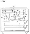
- Fig. 1 is a structure diagram showing a general view of an electrophotographic copying machine related to an embodiment of the invention
- Fig. 2 is a diagram showing cleaning of a photoreceptor drum
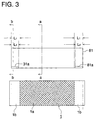
- Fig. 3 is a diagram showing an arrangement of a photoreceptor drum and a cleaning blade.
- an electrophotographic copying machine as one exmaple of the electrostatic recording apparatus, when photoreceptor drum 1 representing an image carrier or an image carrying member rotates clockwise in the direction shown with arrow mark "a", the photoreceptor drum 1 is charged uniformly by charger 2 as charging means and is subjected to imagewise exposure conducted by exposure unit 3 composed of lamp 31 as exposing means, mirrors 32, 33, 34, 35, 36 and 37 and lens 38, whereby an electrostatic latent image is formed on the surface of the photoreceptor drum 1.
- the latent image is developed by developing device 4, as developing means and a toner image thus formed by the development is transferred onto a transfer sheet by transfer device 5 as transferring means.
- the transfer sheet is conveyed from sheet-feeding unit 9 to the transfer position through sheet-feeding path 10, in synchronization with toner image forming on the photoreceptor drum 1.
- the transferred toner image is fixed on the transfer sheet by fixing device 7.
- the photoreceptor drum 1 is cleaned by cleaning device 8 to be ready for subsequent image forming.
- cleaning blade 81 composed of an elastic body such as urethane rubber or the like is in contact with the surface of the photoreceptor drum 1. Under this condition, when the photoreceptor drum 1 is rotated to move, the cleaning blade 81 removes residues such as toner or the like on the surface.
- Cleaning blade 81 scrapes the surface of the photoreceptor drum 1, with its tip being in contact with a circumferential surface of the photoreceptor drum 1 at an angle to counter against its moving direction "a" as shown in Fig. 2. Under this kind of contact, it tends to be difficult for the cleaning blade 81 to be in contact stably, when the friction between the surface of the photoreceptor drum 1 and the cleaning blade is great.
- the cleaning blade 81 is provided on the electrophotographic copying machine so that the tip of the cleaning blade 81 is in contact with a circumferential surface of the photoreceptor drum 1 at an angle to follow its moving direction "a"
- the tip of the cleaning blade is made to be in contact with a circumferential surface of the photoreceptor drum at an angle to counter against its moving direction.
- blade curling, abnormal noise and chipped edge portions tend to be caused more in the case of contact of the tip at an angle to counter than in the case of contact at an angle to follow. Therefore, it is more preferable that the structure of the invention is applied to an electrostatic recording apparatus wherein the blade tip is in contact at an angle to counter.
- the tip of cleaning blade 81 is formed to be a sharp edge, which, however, tends to lower stability in contact. Between cleaning blade 81 and the surface of photoreceptor drum 1, there exist toner particles which function as a lubricant to lower frictional resistance between them, thereby the cleaning blade 81 scrapes the surface of the photoreceptor drum 1 stably.
- both end portions of the cleaning blade 81 shown as edge portion 81a are chamfered as shown in Fig. 3 in the present embodiment.
- This chamfering processing is to apply heat and pressure for deforming the edge portion 81a. Due to this processing, frictional resistance on each of both end portions is lowered, and blade curling, blade abnormal noise and chipped blade edges were effectively prevented.
- FIG. 4 shows the structure of an apparatus for chamfering processing
- Fig. 4 (a) is a front view
- Fig. 4 (b) is a side view
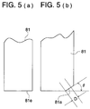
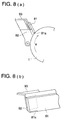
- Fig. 5 is a diagram showing a chamfer of the cleaning blade.
- supporting shaft 41 is fixed on supporting stand 40, and blade supporting member 42 is supported on the supporting shaft 41 to be capable of rising and falling in the direction shown with arrow mark "d".
- blade clamping member 43 On supporting arm 421 of the blade supporting member 42, there is mounted blade clamping member 43 detachably.
- blade clamping member 43 On the blade clamping member 43, there is clamped blade unit 44 detachably.
- the blade unit 44 is composed of blade main body 441 and supporting base portion 442. On the supporting stand 40, there are also provided heating sections 46 each being equipped with heating head 461.
- Blade unit 44 is mounted on the blade clamping member 43 and is clamped thereon with screw 431 to be fixed, then blade supporting member 42 is lowered to the prescribed position, and an edge of cleaning blade 81 is brought into pressure contact with heating head 461 at the prescribed pressure.
- the heating head 461 is set to the prescribed temperature, and both end portions of the edge of the cleaning blade 81 are chamfered by heat and pressure.
- edge 81e of cleaning blade 81 in Fig. 5 (a) is chamfered to be 81a in Fig. 5 (b).
- Fig. 5 (a) is a sectional view taken on line (a) - (a) of cleaning blade 81 in Fig. 3, while Fig. 5 (b) is a sectional view taken on line (b) - (b) of cleaning blade 81 in Fig. 3.
- Control of processing conditions such as a heating temperature, contact pressure and a heating time period can be conducted accurately by data inputted in a control section (not shown). Owing to the control of these chamfering conditions, it is possible to adjust the effect of chamfering by changing variously chamfering width D shown in Fig. 5, namely the width of a flattened portion of edge portion 81a of the cleaning blade 81. In addition to the adjustment of a chamfering width, it is also possible to adjust variously as follows.
- edge portion 81a of cleaning blade 81 coming in contact substantially with a portion other than an image forming area on photoreceptor drum 1 is given heat and pressure to be chamfered.
- pressure equivalent to the weight of a cleaning blade is given.
- edge portion 81e of cleaning blade 81 which comes in contact with image forming area 1a on photoreceptor drum 1 can obtain high cleaning efficiency because it keeps sufficient coefficient of friction, while edge portion 81a of cleaning blade 81 which comes in contact with non-image-forming area 1b on photoreceptor drum 1 scrapes the non-image-forming area 1b smoothly. It is therefore possible to prevent blade curling at an end portion in the lengthwise direction of cleaning blade 81, occurrence of abnormal noises and chipped edge portions 81a, while maintaining cleaning efficiency.
- edge portion 81a can actually be hardened simply by heat without being chamfered. Owing to heat treatment of the edge portion 81a, composition of rubber in the edge portion 81a is changed from a high polymer to a low polymer. Due to this, rubber elasticity of the edge portion 81a is lowered to 10 to 100, compared with rubber elasticity before the heat treatment. Therefore, even when cleaning blade 81 is brought into contact with a circumferential surface of photoreceptor drum 1, edge portion 81a does not follow the rotation of the photoreceptor drum 1 on non-image area 1b where frictional resistance is high on the photoreceptor drum 1.
- edge portion 81a it is therefore possible, by hardening the edge portion 81a only by heat, to prevent blade curling at an end portion in the lengthwise direction of cleaning blade 81, occurrence of abnormal noises and chipped edge portions 81a, while maintaining cleaning efficiency on the image area 1a of the photoreceptor drum 1.
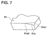
- chamfering processing is conducted so that a width of end portion 81a1 is distributed to be greater than that of inside portion 81a2 without conducting chamfering by melting uniformly in the lengthwise direction of cleaning blade 81.
- a chamfering width at the outermost portion of the cleaning blade 81 is 100 ⁇ m to 500 ⁇ m, and it is gradually reduced as the width approaches the center portion, and at portion 81a2 corresponding to OPC coated portion on photoreceptor drum 1 representing an image carrier, the chamfering width is almost zero.
- a range for chamfering is from the outside of an image forming area on photoreceptor drum 1 to the end of a blade, and the chamfering is not to conduct uniform melting in the lengthwise direction of cleaning blade 81 but to make a width of end portion 81a1 to be greater than that of inside portion 81a2.
- frictional force (force of pressure contact) of the end portion of cleaning blade 81 is reduced, edge portion 81a is hardly deformed, cleaning efficiency is excellent, and durability is excellent without occurrence of blade curling at the end portion of cleaning blade 81, blade abnormal noises and chipped blade edges.
- scattering preventing member 92 is provided on the reverse side or the obverse side of cleaning blade 81 at the position corresponding to end portion 81a1 of cleaning blade 81 to cover the range broader than the chamfered edge portion 81a against photoreceptor drum 1 representing an image carrier.
- a material of the scattering preventing member 92 is PET urethane sheet, and this scattering preventing member 92 is attached on blade holder 93 on the reverse side of cleaning blade 81 to extend along the cleaning blade 81.
- a material of the scattering preventing member 92 is PET or urethane, and this scattering preventing member 92 is glued by a double-sided adhesive tape on cleaning blade 81 which is attached on blade holder 93.
- the scattering preventing member 92 covers the obverse side of the cleaning blade 81.
- a material of scattering preventing member 92 is PET or urethane sheet, and its base portion 92a and tip portion 92b are bent, and the base portion 92a is glued, with double-sided adhesive tape 94, on cleaning blade 81 that is attached on blade holder 93.
- the scattering preventing member 92 can cover the obverse side of the cleaning blade 81 and press its tip portion 92b smoothly against photoreceptor drum 1.
- a cover representing scattering preventing member 92 which is broader than the chamfered portion on the cleaning blade 81, thereby it is possible to prevent that an end portion of the cleaning blade 81 is caught due to reduction of frictional force (pressure contact force) on the end portion, and that an image is adversely affected by the scattering caused by the foregoing, thus, an object can be attained without any troubles.
- Table 1 is a table showing the relation of the processing time, processing temperature and a chamfering width in an occasion wherein cleaning blade 81 is caused by its own weight to be in pressure contact with heating head 461.
- Chamfering width ⁇ m, Time: sec, Temperature: °C 0 sec 5 sec 10 sec 20 sec 30 sec 60 sec 100 sec 150°C - 0 0 0 0 *0 *0 200°C - *0 *0 20 50 90 140 250°C - *0 20 50 70 110 160 280°C - 70 150 200 300 500 800 300°C - 120 180 300 400 600 1000- 400°C - 400 600 800 1000 1000- 1000- 500°C - 600 900 1000- 1000- 1000- 1000- 1000- 1000- 1000- 1000- 1000- 1000- 1000- 1000- 1000- 1000- 1000- 1000- 1000- 1000- 1000- 1000- 1000- 1000- 1000- 1000- 1000- 1000- 1000- 1000- 1000- 1000- 1000- 1000- 1000- 1000- 1000- 1000- 1000-
- Table 2 shows the results of the image forming conducted by using cleaning blades each having a different chamfering width. Table of chamfering width and evaluation of efficiency. A4 size copies in actual quantity of 100,000 were made. Ordinary temperature (20°C), Ordinary humidity (50%), CPM (number of copies per minute) 40 Chamfering width ( ⁇ m) None *0 50 100 200 500 1000 Blade curling C B A A A A A A Toner scattering A A A A A B C
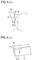
- an edge of cleaning blade 81 is brought into contact with heating head 461 so that horizontal pressure k2 may be greater than vertical pressure k1, and thereby chamfering processing is conducted so that sagged portion 81f may be remained by applying pressure from the H surface side so that no sagged portion may be caused on the surface of the contact (H surface side).
- an edge of a cleaning blade corresponding to a portion touching a non-image-forming area of an image carrier is hardened by heat, as stated above. It is therefore possible to prevent occurrence of curling of a cleaning blade and abnormal noises and occurrence of chipped edges, whereby excellent durability of a cleaning blade can be obtained.
- an edge on the end portion in the lengthwise direction is hardened by heat. Therefore, when it is applied as a cleaning member of an electrostatic recording apparatus, it is possible to prevent occurrence of curling of a cleaning blade and abnormal noises and occurrence of chipped edges, whereby it is possible to make the cleaning blade to be highly durable.
Landscapes
- Physics & Mathematics (AREA)
- General Physics & Mathematics (AREA)
- Cleaning In Electrography (AREA)
Applications Claiming Priority (6)
| Application Number | Priority Date | Filing Date | Title |
|---|---|---|---|
| JP232699/97 | 1997-08-28 | ||
| JP9232699A JPH1173072A (ja) | 1997-08-28 | 1997-08-28 | 静電記録装置及び静電記録用クリーニングブレード |
| JP23269997 | 1997-08-28 | ||
| JP25113597 | 1997-09-16 | ||
| JP251135/97 | 1997-09-16 | ||
| JP25113597A JPH1195631A (ja) | 1997-09-16 | 1997-09-16 | 静電記録装置 |
Publications (2)
| Publication Number | Publication Date |
|---|---|
| EP0899631A2 true EP0899631A2 (de) | 1999-03-03 |
| EP0899631A3 EP0899631A3 (de) | 1999-06-16 |
Family
ID=26530616
Family Applications (1)
| Application Number | Title | Priority Date | Filing Date |
|---|---|---|---|
| EP98116086A Withdrawn EP0899631A3 (de) | 1997-08-28 | 1998-08-26 | Elektrostatisches Aufzeichnungsgerät und Reinigungsklinge |
Country Status (2)
| Country | Link |
|---|---|
| US (1) | US6044245A (de) |
| EP (1) | EP0899631A3 (de) |
Cited By (1)
| Publication number | Priority date | Publication date | Assignee | Title |
|---|---|---|---|---|
| CN103034107A (zh) * | 2011-10-05 | 2013-04-10 | 柯尼卡美能达商用科技株式会社 | 清理刮刀及成像装置 |
Families Citing this family (7)
| Publication number | Priority date | Publication date | Assignee | Title |
|---|---|---|---|---|
| US6711368B2 (en) * | 2001-12-12 | 2004-03-23 | Kabushiki Kaisha Toshiba | Image forming apparatus designed to prevent curling of a cleaning blade |
| US7031634B2 (en) * | 2003-02-07 | 2006-04-18 | Eastman Kodak Company | Blade cleaner cartridge with dust and lint seal blade |
| JP4947938B2 (ja) * | 2005-06-20 | 2012-06-06 | 株式会社リコー | クリーニング装置、プロセスユニット、及び画像形成装置 |
| US7526243B2 (en) * | 2007-07-16 | 2009-04-28 | Xerox Corporation | Vibration method to reduce and/or eliminate friction/noise |
| JP2009282343A (ja) * | 2008-05-23 | 2009-12-03 | Konica Minolta Business Technologies Inc | クリーニング装置及び画像形成装置 |
| JP5849980B2 (ja) * | 2013-03-21 | 2016-02-03 | 富士ゼロックス株式会社 | 転写装置、中間転写装置及び画像形成装置 |
| JP7166822B2 (ja) * | 2018-07-18 | 2022-11-08 | キヤノン株式会社 | クリーニングブレード、クリーニングブレードの製造方法、プロセスカートリッジ及び画像形成装置 |
Family Cites Families (10)
| Publication number | Priority date | Publication date | Assignee | Title |
|---|---|---|---|---|
| GB1468085A (en) * | 1974-05-24 | 1977-03-23 | Serox Corp | Cleaning blade |
| JPS5479637A (en) * | 1977-12-08 | 1979-06-25 | Konishiroku Photo Ind Co Ltd | Cleaning blade for drum of electrophotographic copier |
| JPH0721686B2 (ja) * | 1985-03-18 | 1995-03-08 | キヤノン株式会社 | クリーニングブレード及びこのクリーニングブレードを用いた画像形成装置 |
| JPS61240272A (ja) * | 1985-04-17 | 1986-10-25 | Toshiba Corp | 画像形成装置 |
| JPS62100781A (ja) * | 1985-10-28 | 1987-05-11 | Tokai Rubber Ind Ltd | クリ−ニングブレ−ド |
| JPH01184218A (ja) * | 1988-01-14 | 1989-07-21 | Mazda Motor Corp | レーザ焼入れ方法 |
| JPH0316705A (ja) * | 1989-06-14 | 1991-01-24 | Bando Chem Ind Ltd | 電子写真複写機用クリーニング・ブレードの製造方法 |
| JPH06332350A (ja) * | 1993-05-26 | 1994-12-02 | Ricoh Co Ltd | クリーニングブレード及びその製造方法並びに該クリーニングブレードを用いる画像形成装置 |
| JP3016705B2 (ja) | 1995-03-17 | 2000-03-06 | 松下電子工業株式会社 | 蛍光ランプ |
| JPH0922184A (ja) * | 1995-07-04 | 1997-01-21 | Mita Ind Co Ltd | 静電潜像現像装置 |
-
1998
- 1998-08-25 US US09/139,291 patent/US6044245A/en not_active Expired - Fee Related
- 1998-08-26 EP EP98116086A patent/EP0899631A3/de not_active Withdrawn
Cited By (1)
| Publication number | Priority date | Publication date | Assignee | Title |
|---|---|---|---|---|
| CN103034107A (zh) * | 2011-10-05 | 2013-04-10 | 柯尼卡美能达商用科技株式会社 | 清理刮刀及成像装置 |
Also Published As
| Publication number | Publication date |
|---|---|
| US6044245A (en) | 2000-03-28 |
| EP0899631A3 (de) | 1999-06-16 |
Similar Documents
| Publication | Publication Date | Title |
|---|---|---|
| JPS603195B2 (ja) | 油計量ブレード装置 | |
| JP2000162938A (ja) | 画像形成装置および画像形成装置の像担持体への潤滑剤塗布装置 | |
| US6263175B1 (en) | Image forming apparatus including a charging device with a cleaning member | |
| US6044245A (en) | Electrostatic recording apparatus and cleaning blade | |
| JP3965951B2 (ja) | 潤滑剤塗布装置 | |
| JPH0519671A (ja) | ブレードクリーニング装置 | |
| JP3740990B2 (ja) | 画像形成装置 | |
| JP2947071B2 (ja) | クリーナ、現像器および該クリーナと現像器を用いた電子写真装置 | |
| JP2000181221A (ja) | 画像形成装置 | |
| JPH1195631A (ja) | 静電記録装置 | |
| JPH0990847A (ja) | 電子写真装置における像担持体への潤滑剤供給装置 | |
| JP2004279788A (ja) | 画像形成装置 | |
| JP4109976B2 (ja) | 現像装置及びそれを備える画像形成装置 | |
| US20060088351A1 (en) | Residual toner damming assembly | |
| JP2506645Y2 (ja) | クリ―ニング装置 | |
| JP3451170B2 (ja) | クリーニング装置 | |
| JP2004191406A (ja) | 定着装置及び画像形成装置 | |
| JP2759578B2 (ja) | 定着装置 | |
| JP3342613B2 (ja) | 画像形成装置 | |
| JP2000075757A (ja) | 画像形成装置 | |
| JPH07295451A (ja) | 画像形成装置における潤滑剤供給装置 | |
| JP3292586B2 (ja) | 画像形成装置 | |
| JPS58184981A (ja) | クリ−ニング装置 | |
| JPH0981005A (ja) | 画像形成装置用のクリーニング装置 | |
| JP3291354B2 (ja) | 画像形成装置におけるクリーニング装置 |
Legal Events
| Date | Code | Title | Description |
|---|---|---|---|
| PUAI | Public reference made under article 153(3) epc to a published international application that has entered the european phase |
Free format text: ORIGINAL CODE: 0009012 |
|
| AK | Designated contracting states |
Kind code of ref document: A2 Designated state(s): AT BE CH CY DE DK ES FI FR GB GR IE IT LI LU MC NL PT SE |
|
| AX | Request for extension of the european patent |
Free format text: AL;LT;LV;MK;RO;SI |
|
| PUAL | Search report despatched |
Free format text: ORIGINAL CODE: 0009013 |
|
| AK | Designated contracting states |
Kind code of ref document: A3 Designated state(s): AT BE CH CY DE DK ES FI FR GB GR IE IT LI LU MC NL PT SE |
|
| AX | Request for extension of the european patent |
Free format text: AL;LT;LV;MK;RO;SI |
|
| AKX | Designation fees paid | ||
| REG | Reference to a national code |
Ref country code: DE Ref legal event code: 8566 |
|
| STAA | Information on the status of an ep patent application or granted ep patent |
Free format text: STATUS: THE APPLICATION IS DEEMED TO BE WITHDRAWN |
|
| 18D | Application deemed to be withdrawn |
Effective date: 19991217 |