EP0899687A1 - Verfahren und Vorrichtung zur Detektion von Bewegungsvektoren und Vorrichtung zur Bildkodierung - Google Patents
Verfahren und Vorrichtung zur Detektion von Bewegungsvektoren und Vorrichtung zur Bildkodierung Download PDFInfo
- Publication number
- EP0899687A1 EP0899687A1 EP98115342A EP98115342A EP0899687A1 EP 0899687 A1 EP0899687 A1 EP 0899687A1 EP 98115342 A EP98115342 A EP 98115342A EP 98115342 A EP98115342 A EP 98115342A EP 0899687 A1 EP0899687 A1 EP 0899687A1
- Authority
- EP
- European Patent Office
- Prior art keywords
- block
- motion vector
- coded
- correlation
- image
- Prior art date
- Legal status (The legal status is an assumption and is not a legal conclusion. Google has not performed a legal analysis and makes no representation as to the accuracy of the status listed.)
- Granted
Links
Images


Classifications
-
- H—ELECTRICITY
- H04—ELECTRIC COMMUNICATION TECHNIQUE
- H04N—PICTORIAL COMMUNICATION, e.g. TELEVISION
- H04N19/00—Methods or arrangements for coding, decoding, compressing or decompressing digital video signals
- H04N19/42—Methods or arrangements for coding, decoding, compressing or decompressing digital video signals characterised by implementation details or hardware specially adapted for video compression or decompression, e.g. dedicated software implementation
- H04N19/43—Hardware specially adapted for motion estimation or compensation
-
- H—ELECTRICITY
- H04—ELECTRIC COMMUNICATION TECHNIQUE
- H04N—PICTORIAL COMMUNICATION, e.g. TELEVISION
- H04N5/00—Details of television systems
- H04N5/14—Picture signal circuitry for video frequency region
- H04N5/144—Movement detection
- H04N5/145—Movement estimation
-
- G—PHYSICS
- G06—COMPUTING OR CALCULATING; COUNTING
- G06T—IMAGE DATA PROCESSING OR GENERATION, IN GENERAL
- G06T7/00—Image analysis
- G06T7/20—Analysis of motion
- G06T7/223—Analysis of motion using block-matching
- G06T7/238—Analysis of motion using block-matching using non-full search, e.g. three-step search
-
- H—ELECTRICITY
- H04—ELECTRIC COMMUNICATION TECHNIQUE
- H04N—PICTORIAL COMMUNICATION, e.g. TELEVISION
- H04N19/00—Methods or arrangements for coding, decoding, compressing or decompressing digital video signals
- H04N19/50—Methods or arrangements for coding, decoding, compressing or decompressing digital video signals using predictive coding
- H04N19/503—Methods or arrangements for coding, decoding, compressing or decompressing digital video signals using predictive coding involving temporal prediction
- H04N19/51—Motion estimation or motion compensation
-
- G—PHYSICS
- G06—COMPUTING OR CALCULATING; COUNTING
- G06T—IMAGE DATA PROCESSING OR GENERATION, IN GENERAL
- G06T2207/00—Indexing scheme for image analysis or image enhancement
- G06T2207/10—Image acquisition modality
- G06T2207/10016—Video; Image sequence
-
- G—PHYSICS
- G06—COMPUTING OR CALCULATING; COUNTING
- G06T—IMAGE DATA PROCESSING OR GENERATION, IN GENERAL
- G06T2207/00—Indexing scheme for image analysis or image enhancement
- G06T2207/20—Special algorithmic details
- G06T2207/20048—Transform domain processing
- G06T2207/20052—Discrete cosine transform [DCT]
Definitions
- the present invention relates to technology for efficiently detecting a motion vector during the motion compensated coding of a moving picture.
- a block matching method is generally used for detecting a motion vector out of a moving picture.
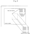
- Figure 8 is a conceptual diagram illustrating a block matching method.
- an estimated value representing correlation is first calculated between an image component included in a block to be coded, out of which the motion vector is to be detected, and an image component in each candidate block within a search range, which block has the same size as the block to be coded. Then, the displacement from a block, located at the same position as the block to be coded, to a candidate block having the highest correlation represented by the estimated value is defined as the motion vector.
- the estimated value of correlation a total sum of the absolute values of differences between pairs of mutually associated pixels in the pair of blocks is used, for example. In this case, the higher the correlation between the image components (i.e., pixels) is, the smaller the estimated value becomes.
- the estimated values are calculated between a single block to be coded and many candidate blocks within the search range.
- a huge quantity of calculation is required.
- the power consumed by a motion vector detecting apparatus is also enormous.
- Sub-sampling is one of such techniques.
- some pixels of a block to be coded and the counterparts of the blocks within the search range are decimated, and a motion vector is obtained with respect to the decimated images by the block matching method.
- the sub-sampling method if the number of pixels included in the block to be coded is reduced to 1/N (where N is a positive integer) through decimation, then the quantity of estimated value calculation is also reduced to 1/N. As a result, the power consumption can also be reduced to about 1/N.
- the decimated image loses the detailed features of the original image.
- the quantity of estimated value calculation can be reduced, but the performance of motion vector detection is inferior.
- the reduction of the quantity of estimated value calculation and the power consumption is preferred even if the performance of motion vector detection is deteriorated to a certain degree.
- the object of the present invention is selectively and more adaptively setting sub-sampling than conventional technology in terms of detection performance and power consumption.
- the motion vector detecting apparatus includes: first image storage means for storing an image of a block to be coded; second image storage means for storing an image within a search range; correlation calculation means including a plurality of correlation calculation blocks for calculating correlation between the block to be coded and each associated candidate block within the search range, each said correlation calculation block being supplied with a different group of pixels out of the block to be coded from the first image storage means and an associated group of pixels of each said associated candidate block from the second image storage means and calculating the correlation between the two groups of pixels supplied; control means for controlling the correlation calculation means by selectively operating at least one of the correlation calculation blocks; and correlation determination means for determining the correlation between the block to be coded and each said associated candidate block based on an output of the correlation calculation block operated in accordance with the control of the control means.
- the control means preferably selects at least one of the correlation calculation blocks in accordance with image feature information of the block to be coded or operating state information of the motion vector detecting apparatus.
- the present invention is also embodied in a method for detecting a motion vector.
- the method includes the steps of: a) calculating correlation between a block to be coded in a target frame and each associated candidate block within a search range in a search frame; and b) detecting the motion vector of the block to be coded based on the correlation calculated in the step a).
- step a) sub-sampling during the calculation of correlation is selectively set in accordance with image feature information of the block to be coded.
- the frequency components of the block to be coded are preferably used as the image feature information.
- the DCT components or the motion vector of a block in a frame previous to the target frame may also be used as the image feature information.
- the block in the previous frame is preferably located at the same position as or in the vicinity of the block to be coded.
- Another method for detecting a motion vector includes the steps of: a) calculating correlation between a block to be coded in a target frame and each associated candidate block within a search range in a search frame; and b) detecting the motion vector of the block to be coded based on the correlation calculated in the step a).
- step a) sub-sampling during the calculation of correlation is selectively set in accordance with operating state information of an apparatus implementing the method.
- Information indicating whether the apparatus implementing the method is operated in a mobile state or in an immobile state is preferably used as the operating state information.
- information indicating the power left in a battery functioning as a power supply for the apparatus implementing the method may also be used as the operating state information.
- the present invention is further embodied in an image coding apparatus for performing motion compensated coding on a moving picture.
- the image coding apparatus includes a motion vector detecting section for calculating correlation between a block to be coded in a target frame and each associated candidate block within a search range in a search frame and thereby detecting the motion vector of the block to be coded based on the correlation calculated.
- the motion vector detecting section selectively sets sub-sampling during the calculation of the correlation in accordance with image feature information of the block to be coded.
- the image coding apparatus preferably further includes a DCT section for performing a discrete cosine transform on an image.
- the motion vector detecting section preferably selectively sets sub-sampling by using DCT components of a block in a frame previous to the target frame as the image feature information.
- the DCT components are obtained by the DCT section, and the block in the previous frame is located at the same position as or in the vicinity of the block to be coded.
- the motion vector detecting section preferably selectively sets sub-sampling by using a motion vector of a block in a frame previous to the target frame as the image feature information.
- the block in the previous frame is located at the same position as or in the vicinity of the block to be coded.
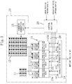
- Figure 1 is a block diagram illustrating the configuration of a motion vector detecting apparatus in one embodiment of the present invention.
- the reference numeral 11 denotes a first image storage section for storing the image of a block to be coded.
- 12 denotes a second image storage section for storing an image within a search range.
- 13 denotes a correlation calculation section, including four correlation calculation blocks 13a through 13d , for calculating the correlation between the block to be coded and candidate blocks within the search range.
- Each of the first to fourth correlation calculation blocks 13a through 13d is supplied with a different group of pixels of the block to be coded from the first image storage section 11 and an associated group of pixels of the candidate block from the second image storage section 12 .
- each correlation calculation block calculates the correlation between the two groups of pixels supplied. As an estimated value of correlation, a total sum of absolute values of differences between the pixels is used.
- pixels can be sub-sampled every other pixel both horizontally and vertically.
- the pixels stored in the first image storage section 11 are classified into the four groups of: Group of Pixels ⁇ , Group of Pixels ⁇ , Group of Pixels ⁇ and Group of Pixels ⁇ .
- Group of Pixels ⁇ are supplied to the first correlation calculation block 13a .
- Group of Pixels ⁇ are supplied to the second correlation calculation block 13b .
- Group of Pixels ⁇ are supplied to the third correlation calculation block 13c .
- Group of Pixels ⁇ are supplied to the fourth correlation calculation block 13d .
- the destination of each group of pixels stored in the second image storage section 12 is variable depending upon the setting of the candidate blocks. Addressing of the second image storage section 12 is performed by an address generation section 15 .
- the reference numeral 20 denotes a control section for selectively operating part or all of the first to fourth correlation calculation blocks 13a through 13d by supplying an enable signal EN .
- the control section 20 selects either a mode in which all of the first to fourth correlation calculation blocks 13a through 13d are operated or a mode in which part of the first to fourth correlation calculation blocks 13a through 13d is/are operated. If sub-sampling is not performed during motion vector detection, all of the first to fourth correlation calculation blocks 13a through 13d are operated. On the other hand, if sub-sampling is performed during the motion vector detection, part of the first to fourth correlation calculation blocks 13a through 13d is/are operated.
- the reference numeral 14 denotes a correlation determination section for determining the correlation between the block to be coded and the candidate blocks based on the outputs EC1 through EC4 of the first to fourth correlation calculation blocks 13a through 13d operated in accordance with the control of the control section 20 .
- the correlation determination section 14 outputs a motion vector MV based on the correlation between the block to be coded and the candidate blocks.
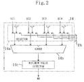
- Figure 2 is a block diagram illustrating the configuration of the correlation determination section 14 shown in Figure 1 .
- the reference numeral 14a denotes a selector for selecting any of the outputs EC1 through EC4 of the first to fourth correlation calculation blocks 13a through 13d and a numerical value "0" in response to the enable signal EN .
- the reference numeral 14b denotes an adder as an arithmetic unit for adding the output values of the selector 14a .
- the reference numeral 14c denotes a minimum value detector for detecting the minimum value out of the outputs of the adder 14b .
- the image of the block to be coded and the image within the search range are supplied from the first and second image storage sections 11 and 12 to the first to fourth correlation calculation blocks 13a through 13d , which receive Group of Pixels ⁇ , Group of Pixels ⁇ , Group of Pixels ⁇ and Group of Pixels ⁇ , respectively.
- the correlation calculation block calculates a total sum of the absolute values of differences between the pixels included in the group from the block to be coded and the pixels included in the group within the search range.
- the first correlation calculation block 13a outputs the total sum EC1 of the absolute values of differences between the pixels included in both Groups ⁇ .
- the second correlation calculation block 13b outputs the total sum EC2 of the absolute values of differences between the pixels included in both Groups ⁇ .
- the third correlation calculation block 13c outputs the total sum EC3 of the absolute values of differences between the pixels included in both Groups ⁇ .
- the fourth correlation calculation block 13d outputs the total sum EC4 of the absolute values of differences between the pixels included in both Groups ⁇ .
- the selector 14a selects any of the outputs EC1 through EC4 of the first to fourth correlation calculation blocks 13a through 13d and a numerical value "0" in response to the enable signal EN . And the selected values are added by the adder 14b . In this case, the selector 14a selects the output(s) of only the operated one(s) from the first to fourth correlation calculation blocks 13a through 13d and selects "0" for the non-operated one(s), instead of the output(s) thereof. Thus, the adder 14b outputs the total sum of the outputs of the operated ones among the first to fourth correlation calculation blocks 13a through 13d .
- a value obtained by adding the total sum of the absolute values of differences between the pixels included in both Groups A and the total sum of the absolute values of differences between the pixels included in both Groups B corresponds to the total sum of the absolute values of differences between the pixels included in Group A and the pixels included in Group B .
- the output of the adder 14b corresponds to the total sum of the absolute values of differences between the pixels included in the two groups supplied to the operated correlation calculation blocks, i.e., an estimated value of correlation.
- the minimum value detector 14c detects a minimum value out of the estimated values of correlation output from the adder 14b , and detects a motion vector corresponding to the candidate block having the minimum estimated value of correlation.
- the control section 20 selects the groups of pixels required for calculating the estimated values of correlation in accordance with the image feature information S1 of the block to be coded and the operating state information S2 of the motion vector detecting apparatus. And the control section 20 operates only the correlation calculation blocks, to which the required groups of pixels are supplied, by providing the enable signal EN thereto.
- the motion vector detecting apparatus of the present invention selects groups of pixels, required for calculating the estimated values of correlation, from the block to be coded and the search range in accordance with the image feature information S1 and the operating state information S2 . Then, the apparatus calculates the estimated values of correlation only for the selected groups of pixels, thereby detecting a motion vector.
- the non-selected group of pixels have been virtually decimated from the block to be coded and the search range. As a result, motion vector detection through sub-sampling is realized.
- the motion vector can be detected with requisite minimum power.
- Figure 3 is a block diagram illustrating an exemplary image coding apparatus including the motion vector detecting apparatus shown in Figure 1 .
- the reference numeral 1 denotes an image coding apparatus for generating coded data from image data.
- the reference numeral 41 denotes a battery as a power supply for the image coding apparatus 1 .
- the reference numeral 42 denotes a CPU for controlling the operation of the image coding apparatus 1 .
- the reference numeral 43 denotes a preprocessing section for pre-processing the image data to be supplied to the image coding apparatus 1 .
- the reference numeral 44 denotes a frame memory for storing the image data output from the image coding apparatus 1 .
- the image coding apparatus 1 includes: an image input section 31 ; a motion vector detection section 10 ; a discrete cosine transform (DCT) section 32 ; a quantization section 33 ; a variable length coding (VLC) section 34 ; and a local decode section 35 as respective processing blocks.
- the motion vector detecting section 10 has the configuration shown in Figure 1 .
- the local decode section 35 performs inverse quantization and inverse DCT on the quantized data, thereby restoring an image.
- a controller 30 controls the respective processing blocks.
- a memory interface (I/F) section 36 transfers data between the respective processing blocks and the frame memory 44 .
- the function of the control section 20 shown in Figure 1 is performed by the controller 30 and the CPU 42 .
- the controller 30 and the CPU 42 receive the image feature information S1 from the DCT section 32 , the motion vector detection section 10 or the preprocessing section 43 , and also receives operating state information S2 representing the power left in the battery 41 . And in accordance with the information S1 and S2 , the controller 30 and the CPU 42 control the motion vector detection section 10 to selectively set sub-sampling.
- Figures 4(a) and 4(b) are diagrams illustrating the relationships between images and frequency components, where the axis of abscissas represents the positions of pixels and the axis of ordinates represents the values of respective pixels.
- Figure 4(a) illustrates an image in which respective pixels have values A and B every other pixel. This image has frequency components having a period of two pixel intervals.
- Figure 4(b) illustrates an image obtained by sub-sampling the image shown in Figure 4(a) every other pixel. As can be understood from the comparison between Figures 4(a) and 4(b) , the feature of the image shown in Figure 4(a) that pixel values vary every other pixel is lost as a result of the sub-sampling performed every other pixel.
- the feature of an image is sometimes lost but sometimes not lost depending upon the direction of sub-sampling and the arrangement of pixels in the image.
- the image of a block to be coded such as that shown in Figure 5(a) is sub-sampled horizontally every other pixel
- the results are as shown in Figure 5(b) .
- the performance of motion vector detection does not deteriorate so much.
- the image shown in Figure 5(a) is sub-sampled vertically every other pixel, then the feature of the original image of the block to be coded does not remain after the sub-sampling has been performed as shown in Figure 5(c) . In such a case, the performance of motion vector detection does deteriorate and an erroneous motion vector is possibly detected.
- sub-sampling is selectively set by using the frequency components of the block to be coded as the image feature information S1 .
- the estimated values are calculated by using Groups of Pixels ⁇ and ⁇ (or Groups of Pixels ⁇ and ⁇ ).
- the estimated values are calculated by using Group of Pixels ⁇ only. Setting of sub-sampling may be performed similarly when attention is paid to an image horizontally.
- the operating state information S2 includes whether an image coding apparatus is operated in a mobile state or in an immobile state. Specifically, if the apparatus is operated in an immobile state, then power can be stably supplied thereto in general. Thus, it is preferable to maximize the performance of motion vector detection without performing sub-sampling. On the other hand, if the apparatus is operated in a mobile state, it is sometimes preferable to perform sub-sampling depending upon how much power is left in the battery or how much time the apparatus is to used thereafter.
- Figure 6 is a flow chart illustrating the flow of sub-sampling setting processing in this embodiment.
- Step S11 the CPU 42 receives information indicating the power left in the battery 41 as the operating state information S2 .
- the CPU 42 instructs the image coding apparatus 1 whether or not the power consumption should be reduced. If it is not necessary to reduce the power consumption, motion vector detection is performed without sub-sampling while respecting the performance of motion vector detection more than the reduction of power consumption.
- the controller 30 sets sub-sampling in accordance with the image feature information S1 .
- the DCT components obtained by the DCT section 32 for the block to be coded are used as the image feature information S1 .
- the discrete cosine transform is an orthogonal transform using a cosine function as a base function, and is a calculation for obtaining the frequency components included in the object to be transformed.
- Figure 7 illustrates exemplary DCT components for a block to be coded.
- the DCT components such as those shown in Figure 7 represent the distribution of frequency components in the block to be coded.
- the larger the value of a component located in the vicinity of the upper left corner is, the larger number of low-frequency components exist.
- the larger the value of a component located in the vicinity of the lower right corner is, the larger number of high-frequency components exist.
- the variation of the component values in the horizontal direction represents the frequency distribution in the horizontal direction
- the variation of the component values in the vertical direction represents the frequency distribution in the vertical direction.
- the frequency in the horizontal direction is low, whereas the frequency in the vertical direction is high.
- horizontal sub-sampling is preferably performed, but vertical sub-sampling is preferably not performed.
- the power consumption can be reduced by operating only the first and second correlation calculation blocks 13a and 13b .
- the sum of the values of two leftmost components on the uppermost row is assumed to be a horizontal frequency value ⁇ fH
- the sum of the values of two uppermost components on the leftmost column is assumed to be a vertical frequency value ⁇ fV .
- the sub-sampling is set horizontally and vertically.
- Step S12 if the horizontal frequency value ⁇ fH is equal to or larger than a predetermined value H0 , then the horizontal frequency of the block to be coded is determined low and it is determined in Step S13 that horizontal sub-sampling should be performed. On the other hand, if the horizontal frequency value ⁇ fH is smaller than the predetermined value H0 , then the horizontal frequency of the block to be coded is determined high and horizontal sub-sampling is not performed.
- Step S14 if the vertical frequency value ⁇ fV is equal to or larger than a predetermined value V0 , then the vertical frequency of the block to be coded is determined low and it is determined in Step S15 that vertical sub-sampling should be performed. On the other hand, if the vertical frequency value ⁇ fV is smaller than the predetermined value V0 , then the vertical frequency of the block to be coded is determined high and vertical sub-sampling is not performed.
- Step S16 a motion vector is detected in accordance with the setting of sub-sampling.
- An image coding apparatus for detecting a motion vector generally includes a DCT section, and therefore there is no need to provide a new function for calculating DCT components therefor.
- the DCT calculation is performed after the motion vector has been detected.
- the DCT components are to be used for setting sub-sampling as is done in this embodiment, not only an originally intended DCT calculation but also an additional DCT calculation for setting sub-sampling are required to be performed, which adversely increases the quantity of calculation.
- sub-sampling may be set by making the preprocessing section 43 extract the image feature, such as DCT components, of the block to be coded.
- the CPU 42 may make the controller 30 set the sub-sampling mode during the motion vector detection in accordance with the image feature information S1 supplied from the preprocessing section 43 .
- the controller 30 may set the sub-sampling mode during the motion vector detection in accordance with the image feature information S1 supplied from the image input section 31 .
- the DCT components of a block which is located at the same position as the block to be coded in a frame previous to the target frame and which have already been calculated, may also be used for setting sub-sampling.
- a block has a similar image feature to that of a neighboring block.
- the DCT components of a block in the vicinity of the block to be coded or the DCT components of a block located at the same position as the block to be coded in a frame previous to the target frame may be used for setting sub-sampling.
- the image feature information S1 not only the frequency components but also information about the motion of an image may be used. Specifically, in view of the fact that the resolution of human eyes decreases when one sees an object moving fast, sub-sampling may be performed if the block to be coded moves to a large extent, but may not be performed if the motion is small.
- the image feature information S1 representing the motion of the block to be coded the motion vector of a block, which is located at the same position as or in the vicinity of the block to be coded in a frame previous to the target frame and which has already been detected, may be used.
- the image of the block to be coded and the image within the search range are each classified into four groups of pixels and the correlation calculation section 13 is constituted by four correlation calculation blocks 13a through 13d .
- the quantity of calculation performed by the motion vector detection section 10 becomes 100 to 1,000 times as large as those of the other processing blocks in the image coding apparatus 1 .
- the quantity of calculation for obtaining estimated values is: (number of times of calculation per pixel) ⁇ (number of pixels in block to be coded) ⁇ (number of candidate blocks) .
- the quantity of calculation per block to be coded is "786,432".
- a moving picture which has a size of 720 horizontal pixels by 480 vertical pixels and consists of 30 images per second, includes 40,500 blocks to be coded (each consisting of 16 ⁇ 16 pixels) per second.
- the motion vector detection section 10 is required to perform as enormous calculations as about 31 GOP's, thereby consuming huge power.
- the power consumption of the motion vector detection section 10 presumably corresponds to about 1/2 to about 1/4 of the power consumed by the entire apparatus.
- sub-sampling one of the techniques for detecting a motion vector with reduced power, is employed and is adaptively set in accordance with the operating state of the image coding apparatus and the features of images. Specifically, if the power consumption should be reduced (like when there is not so much power left in the battery of a mobile unit), sub-sampling is employed as a matter of principle. However, by avoiding the use of sub-sampling for an image having high-frequency components so as to prevent the quality of the image from being deteriorated, the present invention can reduce power consumption while simultaneously maintaining the image quality. Thus, the present invention is effectively applicable to the use of a battery-driven apparatus such as a mobile unit in a long-time mode and to the power saving control in accordance with the power left in the battery.
- the present invention adaptively sets sub-sampling in accordance with the image feature information such as the frequency components of a block to be coded and the operating state information such as the power left in a battery.
- the image feature information such as the frequency components of a block to be coded
- the operating state information such as the power left in a battery.
- correlation calculation blocks are selectively operated in accordance with the setting of sub-sampling, thereby detecting a motion vector with requisite minimum power.
Landscapes
- Engineering & Computer Science (AREA)
- Multimedia (AREA)
- Signal Processing (AREA)
- Computer Vision & Pattern Recognition (AREA)
- Physics & Mathematics (AREA)
- General Physics & Mathematics (AREA)
- Theoretical Computer Science (AREA)
- Compression Or Coding Systems Of Tv Signals (AREA)
- Image Analysis (AREA)
- Image Processing (AREA)
Applications Claiming Priority (3)
| Application Number | Priority Date | Filing Date | Title |
|---|---|---|---|
| JP22922097 | 1997-08-26 | ||
| JP229220/97 | 1997-08-26 | ||
| JP22922097 | 1997-08-26 |
Publications (2)
| Publication Number | Publication Date |
|---|---|
| EP0899687A1 true EP0899687A1 (de) | 1999-03-03 |
| EP0899687B1 EP0899687B1 (de) | 2004-01-28 |
Family
ID=16888719
Family Applications (1)
| Application Number | Title | Priority Date | Filing Date |
|---|---|---|---|
| EP98115342A Expired - Lifetime EP0899687B1 (de) | 1997-08-26 | 1998-08-14 | Verfahren und Vorrichtung zur Detektion von Bewegungsvektoren und Vorrichtung zur Bildkodierung |
Country Status (5)
| Country | Link |
|---|---|
| US (1) | US6169766B1 (de) |
| EP (1) | EP0899687B1 (de) |
| KR (1) | KR100559687B1 (de) |
| CN (1) | CN1119866C (de) |
| DE (1) | DE69821298T2 (de) |
Cited By (2)
| Publication number | Priority date | Publication date | Assignee | Title |
|---|---|---|---|---|
| WO2016144443A1 (en) * | 2015-03-06 | 2016-09-15 | Qualcomm Incorporated | Method and apparatus for low complexity quarter pel generation in motion search |
| GB2572497A (en) * | 2012-04-04 | 2019-10-02 | Snell Advanced Media Ltd | Video sequence processing |
Families Citing this family (12)
| Publication number | Priority date | Publication date | Assignee | Title |
|---|---|---|---|---|
| US6411651B1 (en) * | 1998-06-26 | 2002-06-25 | Compaq Information Technologies Group, L.P. | Method and system for distributed video compression in personal computer architecture |
| US6671321B1 (en) * | 1999-08-31 | 2003-12-30 | Mastsushita Electric Industrial Co., Ltd. | Motion vector detection device and motion vector detection method |
| KR100767489B1 (ko) * | 2000-03-18 | 2007-10-16 | 주식회사 팬택앤큐리텔 | 벡터 기술자 표현장치 및 이를 이용한 멀티미디어 데이터 검색장치 |
| US6809840B1 (en) * | 2000-06-23 | 2004-10-26 | Eastman Kodak Company | Image processing method for adaptively sub-sampling an image |
| EP1590965A2 (de) | 2003-01-29 | 2005-11-02 | Koninklijke Philips Electronics N.V. | Videokodierungsverfahren für handgeräten |
| US20050058203A1 (en) * | 2003-09-17 | 2005-03-17 | Fernandes Felix C. | Transcoders and methods |
| JP2006203724A (ja) * | 2005-01-24 | 2006-08-03 | Toshiba Corp | 画像圧縮装置及び画像圧縮方法 |
| CN101238714B (zh) * | 2005-08-12 | 2012-03-28 | Nxp股份有限公司 | 数字图像稳定化方法和系统 |
| KR100996542B1 (ko) * | 2008-03-31 | 2010-11-24 | 성균관대학교산학협력단 | 실시간 모션 검출 영상 처리 장치 및 그 방법 |
| JP5668587B2 (ja) * | 2011-04-19 | 2015-02-12 | ソニー株式会社 | 画像処理装置、画像処理方法及びプログラム |
| KR101449853B1 (ko) * | 2013-05-23 | 2014-10-13 | 경희대학교 산학협력단 | 스테레오 영상의 블록 매칭 장치 |
| KR102198852B1 (ko) * | 2014-03-24 | 2021-01-05 | 삼성전자 주식회사 | 홍채 인식 장치 및 이를 포함하는 모바일 장치 |
Citations (3)
| Publication number | Priority date | Publication date | Assignee | Title |
|---|---|---|---|---|
| WO1994003014A1 (en) * | 1992-07-24 | 1994-02-03 | Koz Mark C | Low power video security monitoring system |
| EP0732670A2 (de) * | 1995-03-16 | 1996-09-18 | Deutsche Thomson-Brandt Gmbh | Verfahren und Schaltungsanordnung zur Unterabtastung bei Bewegungsschätzung |
| JPH09200542A (ja) * | 1996-01-18 | 1997-07-31 | Fuji Xerox Co Ltd | 予測符号化装置、復号装置、予測符号化方法、および、画像処理装置 |
Family Cites Families (17)
| Publication number | Priority date | Publication date | Assignee | Title |
|---|---|---|---|---|
| JPS63296583A (ja) | 1987-05-28 | 1988-12-02 | Fujitsu Ltd | 画像符号化方式 |
| JPH0233286A (ja) | 1988-07-22 | 1990-02-02 | Fujitsu Ltd | 動ベクトル検出方式 |
| JPH0549023A (ja) | 1991-08-08 | 1993-02-26 | Nec Corp | 動画像の動き情報検出方式 |
| KR950005651B1 (ko) * | 1992-10-29 | 1995-05-27 | 대우전자주식회사 | 움직임 벡터 검출장치 및 방법 |
| JP3001754B2 (ja) | 1993-10-06 | 2000-01-24 | 日本電信電話株式会社 | 階層的動ベクトル検出装置 |
| KR0122748B1 (ko) * | 1993-12-28 | 1997-11-17 | 배순훈 | 디지탈 동영상 부호화기의 움직임 추정장치 |
| TW297794B (de) * | 1994-09-20 | 1997-02-11 | Ain Kotei Gigyutsu Kk | |
| JPH08116540A (ja) * | 1994-10-14 | 1996-05-07 | Sanyo Electric Co Ltd | 領域分割を用いた画像符号化装置及び画像復号化装置 |
| US5825426A (en) * | 1994-10-18 | 1998-10-20 | Intel Corporation | Video subsampling mode decisions based upon interpolation error measures |
| KR0154921B1 (ko) * | 1994-12-30 | 1998-11-16 | 배순훈 | 동영상 부호화 장치에 이용하기 위한 움직임 추정기 |
| US5712799A (en) * | 1995-04-04 | 1998-01-27 | Chromatic Research, Inc. | Method and structure for performing motion estimation using reduced precision pixel intensity values |
| US5731850A (en) * | 1995-06-07 | 1998-03-24 | Maturi; Gregory V. | Hybrid hierarchial/full-search MPEG encoder motion estimation |
| JP3283159B2 (ja) | 1995-07-07 | 2002-05-20 | 日本電信電話株式会社 | ソフトウェアによる画像符号化方法 |
| KR100230838B1 (ko) * | 1995-09-29 | 1999-11-15 | 배순훈 | 영상부호기 |
| JP3189655B2 (ja) | 1995-12-14 | 2001-07-16 | 松下電器産業株式会社 | 動きベクトル検出装置およびその方法 |
| JPH1051793A (ja) | 1996-08-05 | 1998-02-20 | Nippon Telegr & Teleph Corp <Ntt> | ブロックマッチング装置 |
| KR100218374B1 (ko) * | 1997-05-30 | 1999-09-01 | 구본준 | 움직임 추정방법 |
-
1998
- 1998-08-14 EP EP98115342A patent/EP0899687B1/de not_active Expired - Lifetime
- 1998-08-14 DE DE69821298T patent/DE69821298T2/de not_active Expired - Lifetime
- 1998-08-25 CN CN98117377A patent/CN1119866C/zh not_active Expired - Fee Related
- 1998-08-25 US US09/139,653 patent/US6169766B1/en not_active Expired - Lifetime
- 1998-08-26 KR KR1019980034621A patent/KR100559687B1/ko not_active Expired - Fee Related
Patent Citations (3)
| Publication number | Priority date | Publication date | Assignee | Title |
|---|---|---|---|---|
| WO1994003014A1 (en) * | 1992-07-24 | 1994-02-03 | Koz Mark C | Low power video security monitoring system |
| EP0732670A2 (de) * | 1995-03-16 | 1996-09-18 | Deutsche Thomson-Brandt Gmbh | Verfahren und Schaltungsanordnung zur Unterabtastung bei Bewegungsschätzung |
| JPH09200542A (ja) * | 1996-01-18 | 1997-07-31 | Fuji Xerox Co Ltd | 予測符号化装置、復号装置、予測符号化方法、および、画像処理装置 |
Non-Patent Citations (3)
| Title |
|---|
| HILDENBRAND K ET AL: "MOTION ESTIMATION IN THE HERMES VIDEOCODEC", FREQUENZ, vol. 47, no. 11/12, November 1993 (1993-11-01), pages 303 - 309, XP000426383 * |
| PATENT ABSTRACTS OF JAPAN vol. 097, no. 011 28 November 1997 (1997-11-28) * |
| ZACCARIN A ET AL: "FAST ALGORITHMS FOR BLOCK MOTION ESTIMATION*", MULTIDIMENSIONAL SIGNAL PROCESSING, SAN FRANCISCO, MAR. 23 - 26, 1992, vol. III, IEEE, pages 449 - 452, XP000378965 * |
Cited By (4)
| Publication number | Priority date | Publication date | Assignee | Title |
|---|---|---|---|---|
| GB2572497A (en) * | 2012-04-04 | 2019-10-02 | Snell Advanced Media Ltd | Video sequence processing |
| GB2572497B (en) * | 2012-04-04 | 2019-12-18 | Snell Advanced Media Ltd | Video sequence processing |
| WO2016144443A1 (en) * | 2015-03-06 | 2016-09-15 | Qualcomm Incorporated | Method and apparatus for low complexity quarter pel generation in motion search |
| US10291932B2 (en) | 2015-03-06 | 2019-05-14 | Qualcomm Incorporated | Method and apparatus for low complexity quarter pel generation in motion search |
Also Published As
| Publication number | Publication date |
|---|---|
| CN1213230A (zh) | 1999-04-07 |
| EP0899687B1 (de) | 2004-01-28 |
| CN1119866C (zh) | 2003-08-27 |
| US6169766B1 (en) | 2001-01-02 |
| DE69821298D1 (de) | 2004-03-04 |
| KR19990023880A (ko) | 1999-03-25 |
| KR100559687B1 (ko) | 2006-08-30 |
| DE69821298T2 (de) | 2004-07-01 |
Similar Documents
| Publication | Publication Date | Title |
|---|---|---|
| US7362808B2 (en) | Device for and method of estimating motion in video encoder | |
| US9769491B2 (en) | Low complexity real-time video coding | |
| JP3226020B2 (ja) | 動きベクトル検出装置 | |
| EP0899687A1 (de) | Verfahren und Vorrichtung zur Detektion von Bewegungsvektoren und Vorrichtung zur Bildkodierung | |
| US20010012403A1 (en) | An image coding process and notion detecting process using bidirectional prediction | |
| JPH09179987A (ja) | 動きベクトル検出方法及び動きベクトル検出装置 | |
| US20240031576A1 (en) | Method and apparatus for video predictive coding | |
| JPH05328333A (ja) | 動きベクトル検出装置 | |
| US20050123039A1 (en) | Motion estimation method for motion picture encoding and recording medium having program recorded thereon to implement the motion estimation method | |
| US6539058B1 (en) | Methods and apparatus for reducing drift due to averaging in reduced resolution video decoders | |
| KR100843418B1 (ko) | 화상 부호화 장치 및 화상 부호화 방법 | |
| KR20010030652A (ko) | 화상 부호화 시스템 | |
| JP3269031B2 (ja) | 動きベクトル検出装置および動きベクトル検出方法、並びに画像符号化装置 | |
| KR100413770B1 (ko) | 완전 탐색블록 정합회로 및 완전 탐색블록 정합방법 | |
| JP4488805B2 (ja) | 動きベクトル検出装置および方法 | |
| JP3432039B2 (ja) | 画像符号化方法及びその装置 | |
| JPH0262178A (ja) | 画像処理装置の動き検出方式 | |
| JP2608909B2 (ja) | 動画像の予測符号化方式 | |
| JPH08242454A (ja) | グローバル動きパラメタ検出方法 | |
| JPH07288817A (ja) | 動きベクトル検出装置 | |
| EP1553781A2 (de) | Verfahren und Vorrichtung zur Berarbeitung von digitalen Bewegtbildern durch Prädiktion von einem Bewegungskompensationfehler an Hand von einem vorhergehenden Block. | |
| JPH1042300A (ja) | 動きベクトル検出装置 | |
| Arnaudov et al. | Adaptive search pattern for fast motion estimation in HD video | |
| EP0909097B1 (de) | Verfahren und vorrichtung zur bildkodierung | |
| JPH06164413A (ja) | 算術符号の符号化装置および復号化装置の構成方法 |
Legal Events
| Date | Code | Title | Description |
|---|---|---|---|
| PUAI | Public reference made under article 153(3) epc to a published international application that has entered the european phase |
Free format text: ORIGINAL CODE: 0009012 |
|
| AK | Designated contracting states |
Kind code of ref document: A1 Designated state(s): DE FR GB NL |
|
| AX | Request for extension of the european patent |
Free format text: AL;LT;LV;MK;RO;SI |
|
| 17P | Request for examination filed |
Effective date: 19990511 |
|
| AKX | Designation fees paid |
Free format text: DE FR GB NL |
|
| 17Q | First examination report despatched |
Effective date: 19991102 |
|
| GRAP | Despatch of communication of intention to grant a patent |
Free format text: ORIGINAL CODE: EPIDOSNIGR1 |
|
| GRAS | Grant fee paid |
Free format text: ORIGINAL CODE: EPIDOSNIGR3 |
|
| GRAA | (expected) grant |
Free format text: ORIGINAL CODE: 0009210 |
|
| AK | Designated contracting states |
Kind code of ref document: B1 Designated state(s): DE FR GB NL |
|
| REG | Reference to a national code |
Ref country code: GB Ref legal event code: FG4D |
|
| REF | Corresponds to: |
Ref document number: 69821298 Country of ref document: DE Date of ref document: 20040304 Kind code of ref document: P |
|
| ET | Fr: translation filed | ||
| PLBE | No opposition filed within time limit |
Free format text: ORIGINAL CODE: 0009261 |
|
| STAA | Information on the status of an ep patent application or granted ep patent |
Free format text: STATUS: NO OPPOSITION FILED WITHIN TIME LIMIT |
|
| 26N | No opposition filed |
Effective date: 20041029 |
|
| PGFP | Annual fee paid to national office [announced via postgrant information from national office to epo] |
Ref country code: FR Payment date: 20090814 Year of fee payment: 12 |
|
| PGFP | Annual fee paid to national office [announced via postgrant information from national office to epo] |
Ref country code: NL Payment date: 20090816 Year of fee payment: 12 Ref country code: GB Payment date: 20090812 Year of fee payment: 12 Ref country code: DE Payment date: 20090806 Year of fee payment: 12 |
|
| REG | Reference to a national code |
Ref country code: NL Ref legal event code: V1 Effective date: 20110301 |
|
| GBPC | Gb: european patent ceased through non-payment of renewal fee |
Effective date: 20100814 |
|
| REG | Reference to a national code |
Ref country code: FR Ref legal event code: ST Effective date: 20110502 |
|
| PG25 | Lapsed in a contracting state [announced via postgrant information from national office to epo] |
Ref country code: NL Free format text: LAPSE BECAUSE OF NON-PAYMENT OF DUE FEES Effective date: 20110301 |
|
| REG | Reference to a national code |
Ref country code: DE Ref legal event code: R119 Ref document number: 69821298 Country of ref document: DE Effective date: 20110301 |
|
| PG25 | Lapsed in a contracting state [announced via postgrant information from national office to epo] |
Ref country code: DE Free format text: LAPSE BECAUSE OF NON-PAYMENT OF DUE FEES Effective date: 20110301 Ref country code: FR Free format text: LAPSE BECAUSE OF NON-PAYMENT OF DUE FEES Effective date: 20100831 |
|
| PG25 | Lapsed in a contracting state [announced via postgrant information from national office to epo] |
Ref country code: GB Free format text: LAPSE BECAUSE OF NON-PAYMENT OF DUE FEES Effective date: 20100814 |