EP0900616A2 - Lame de scie à configuration de dents de sciage et procédé pour sa fabrication - Google Patents
Lame de scie à configuration de dents de sciage et procédé pour sa fabrication Download PDFInfo
- Publication number
- EP0900616A2 EP0900616A2 EP98116700A EP98116700A EP0900616A2 EP 0900616 A2 EP0900616 A2 EP 0900616A2 EP 98116700 A EP98116700 A EP 98116700A EP 98116700 A EP98116700 A EP 98116700A EP 0900616 A2 EP0900616 A2 EP 0900616A2
- Authority
- EP
- European Patent Office
- Prior art keywords
- teeth
- tooth
- height
- follower
- guide
- Prior art date
- Legal status (The legal status is an assumption and is not a legal conclusion. Google has not performed a legal analysis and makes no representation as to the accuracy of the status listed.)
- Granted
Links
Images


Classifications
-
- B—PERFORMING OPERATIONS; TRANSPORTING
- B23—MACHINE TOOLS; METAL-WORKING NOT OTHERWISE PROVIDED FOR
- B23D—PLANING; SLOTTING; SHEARING; BROACHING; SAWING; FILING; SCRAPING; LIKE OPERATIONS FOR WORKING METAL BY REMOVING MATERIAL, NOT OTHERWISE PROVIDED FOR
- B23D61/00—Tools for sawing machines or sawing devices; Clamping devices for these tools
- B23D61/12—Straight saw blades; Strap saw blades
- B23D61/121—Types of set; Variable teeth, e.g. variable in height or gullet depth; Varying pitch; Details of gullet
- B23D61/1216—Repeating pattern of groups having three or more teeth
-
- B—PERFORMING OPERATIONS; TRANSPORTING
- B23—MACHINE TOOLS; METAL-WORKING NOT OTHERWISE PROVIDED FOR
- B23D—PLANING; SLOTTING; SHEARING; BROACHING; SAWING; FILING; SCRAPING; LIKE OPERATIONS FOR WORKING METAL BY REMOVING MATERIAL, NOT OTHERWISE PROVIDED FOR
- B23D61/00—Tools for sawing machines or sawing devices; Clamping devices for these tools
- B23D61/02—Circular saw blades
- B23D61/021—Types of set; Variable teeth, e.g. variable in height or gullet depth; Varying pitch; Details of gullet
-
- Y—GENERAL TAGGING OF NEW TECHNOLOGICAL DEVELOPMENTS; GENERAL TAGGING OF CROSS-SECTIONAL TECHNOLOGIES SPANNING OVER SEVERAL SECTIONS OF THE IPC; TECHNICAL SUBJECTS COVERED BY FORMER USPC CROSS-REFERENCE ART COLLECTIONS [XRACs] AND DIGESTS
- Y10—TECHNICAL SUBJECTS COVERED BY FORMER USPC
- Y10T—TECHNICAL SUBJECTS COVERED BY FORMER US CLASSIFICATION
- Y10T408/00—Cutting by use of rotating axially moving tool
- Y10T408/89—Tool or Tool with support
- Y10T408/895—Having axial, core-receiving central portion
- Y10T408/8957—Having axial, core-receiving central portion and having stepped cutting edges
Definitions
- the invention relates to a saw blade with one repeating group of teeth coming from an unrestricted chamfered guide tooth with a compared to its width smaller effective ones located in the middle of its tooth tip Cut edge section and a preferably even number set follower teeth, the guide tooth one has a larger tooth height than each of the follower teeth.
- the invention can be used with a band saw blade, i.e. a saw blade with a linear arrangement of the teeth one behind the other, as well a circular saw blade. It is usually only a single guide tooth is provided in the group.
- the Subsequent teeth can be the same, but also different - especially in pairs - have tooth height.
- the invention leaves apply in particular to a bimetal base tape.
- a saw blade is described kind known, which on a base body both unrestricted as well as set teeth, the tips of their teeth consist of a material that is harder than the material of the Basic body is. It can e.g. around tungsten carbide, however also act on high-speed steel.
- the teeth are repetitive Group arranged, the smallest group of one straight guide tooth and two set right and left Subsequent teeth exist.
- the guide tooth has a tooth height that is greater than the common tooth height of the two secondary teeth.
- the guide tooth is phased, so it has in the middle Tooth tip a straight cutting edge section which are arranged in a symmetrical arrangement on the right and left sloping cut edge section connects.
- From DE 36 11 063 A1 is a saw blade at the beginning described type with a group of teeth from one Guide tooth and several secondary teeth known in themselves repetitive cycles are provided.
- the guide tooth has the greatest height and the tooth height decreases in the group, but can also be the same on the following teeth.
- the follow teeth are designed as set teeth and are usually alternating slanted to the left and right provided to this Way to make the width of the cutting channel larger than the width of the body of the saw blade.
- the leading tooth can also be phased.
- the production of different heights Teeth are made by an appropriate milling process or with a tool where the tooth tips are driven by an impact be bent in the direction of the saw band. It closes a grinding process takes place around the cut edges of the teeth to generate the intended height gradation.
- the effective part the length of the ground cutting edges increases in tooth length Tooth in the group, so that the essential cutting work of the leading tooth is to be performed and the two secondary teeth in the essentially only widen the cutting channel, so that a free cut
- From DE 33 00 791 C2 is a saw blade with repetitive Groups of teeth from several consecutive high and several successive low teeth.
- the first group of teeth of equal height contains set and unrestricted Teeth.
- the second group of equally low teeth also contains set and unrestricted teeth.
- Each Group can also have teeth of both heights. Every tooth has first and second, different rake angles and first and second, different clearance angles on. The two different rake and clearance angles can be on each individual tooth through plastic deformation of the tooth tip, in particular by an upsetting process with a pressure stamp are generated at an acute angle to the direction of travel of the saw band is moved.
- the tooth height is also reduced.
- the degree of compression can be adjusted or controlled of the stroke of the pressure stamp can be set or controlled.
- the shape of the teeth can also be cut without milling or grinding. Due to the plastic deformation of a Tooth after tooth a series of teeth can be formed in the between the high teeth of the first group and the low teeth of the second group there is a height difference and the two rake angles and the two relief angles on each Tooth are generated. Also different penetration depths and different divisions can exist within each of the two Groups are realized. It is not recognizable whether the high and low teeth due to the plastic deformation receive different or the same rake angle. Remains on It is not clear whether the height difference that occurs after the plastic deformation the teeth are pre-formed during a previous milling process will or not.
- the invention is based, a comparative task Easy to manufacture saw blade of the type described in the introduction to provide which is advantageously very large rake angle has a reduced vibration behavior and at its use a different chip scale frequency arises.
- this is the case with a saw blade described type achieved in that in any case all follower teeth in the area of their tooth tips one different from each other plastic deformation due to material displacement in Have tape running direction, and that each follower tooth through the different plastic deformation on the one hand increased positive rake angle and on the other hand one has reduced tooth height compared to the guide tooth.
- the invention is based on the idea, at least on the follower teeth primarily due to the different plastic Ultimately deformation of the profiled tooth tips concerned to form different positive rake angles.
- the profiling of the teeth before plastic deformation can be caused in particular by Milling, but also by grinding or punching or by high-energy blasting processes are carried out.
- differences are already understood that occur due to manufacturing tolerances or unavoidable are. For example, already in the manufacture of the Cutter or the profiled grinding wheels larger tolerances be allowed. While striving so far, the tolerances To keep it as small as possible, the invention uses the opposite Path. The same applies to the production and the drive as well as the control of the tool for plastic deformation.
- the pairs of secondary teeth can be at different height levels to each other and to the guide tooth (s) be deformed.
- the different plastic deformation of pairs of follower teeth on different graded levels Height levels will always be in coordination with different ones Cabinet widths made.
- the pair of follow teeth, which on the smallest height level, has the largest cabinet width.
- the pair of follow teeth, which on the greatest height level, has the lowest or smallest cabinet width.
- the pairs of follow teeth that arranged in terms of height also have an intermediate one Cabinet width.
- the saw blade according to the invention has a number of advantages on. Due to the different rake angles due to different plastic deformation while allowing larger tolerances the vibration behavior of the saw blade reduces Sawing in that a different chip scale frequency arises. Extremely large positive rake angles can be achieved not by milling or grinding alone are producible. Due to the plastic deformation of the tooth tips, e.g. can be achieved by upsetting or rolling, the profiled cutting edge gets a greater sharpness. Here the burr formed during milling or grinding in the direction of travel of the saw blade folded. The saw blade according to the invention can finally be produced very easily and inexpensively, in particular in that the follower teeth in one or several groups together or largely simultaneously be plastically deformed. The different plastic deformation can be performed at different levels become.
- These different height levels can be determined by a proportional gradation. For example it makes sense for a group of 7 teeth, the guide tooth, which have a rake angle of about 10 ° after profiling can plastically deform so that he then one Rake angle of about 15 °.
- the guide tooth shows the greatest height at.
- the follower teeth can after the profiling also have a rake angle of 10 °.
- the first couple follower teeth are plastically deformed comparatively more. It gets a rake angle of about 17 °, a height difference -x opposite the guide tooth and a cabinet width (minus Bandwidth) of about a third of the maximum cabinet width of the most deformed pair of follower teeth.
- the second A pair of follower teeth is plastically deformed even more comparatively.
- the third pair of follower teeth is comparatively most plastically deformed. It gets a rake angle of about 21 °, a height difference -3x opposite the guide tooth and the maximum set width.
- the chronological order the teeth in the group are arbitrary. The same applies to other number of teeth in the group.
- the following teeth point to the left and right set teeth, in pairs on the same Height level and are arranged with such limitation that in the projection of all teeth in the band direction in pairs discrete machining areas arise that are not compatible with Machining areas of other teeth overlap.
- the machining areas of the teeth adjoin one another laterally.
- the guide tooth can also be in the area of its tooth tip Different compared to the deformation of the follower teeth have plastic deformation so that it is due to the plastic Deformation on the one hand an enlarged positive rake angle and on the other hand, a comparative compared to the follower teeth has less reduced tooth height.
- the manufacture of the Raw teeth in the group are made by a milling process, whereby in particular, all teeth of a group are milled together
- the raw teeth produced in this way can match, but also have different shapes, particularly with regard to the tooth height and / or one or more positive or neutral rake angle and clearance angle.
- the guide tooth can be a positive one in the area of its tooth tip Rake angle in the range between 5 ° and 25 ° - in particular about 15 ° - and the secondary teeth in the area of their tooth tips positive Rake angle in the range between 5 ° and 30 ° - in particular approximately between 17 ° and 21 °.
- the effective rake angle of the following teeth are usually larger than the effective rake angle of the guide tooth because the follower teeth are usually stronger are plastically deformed than the guide tooth. This can be due to based on the height difference.
- the secondary teeth plastically graded in pairs to different height levels be deformed, with decreasing absolute tooth height with increasing Cabinet width is combined. But it is also possible that Milling raw teeth with different raw chip angles, namely while maintaining the same or different wedge angles between rake angle and clearance angle.
- the saw blade can be between the tooth height of the guide tooth and the tooth height of a follower tooth a height difference in the range of about 0.05 to 0.30 mm - in particular between 0.08 and 0.15 mm - exhibit.
- This difference in height can occur when profiling the raw teeth be fully or partially pre-trained. The final However, the difference in height results from the plastic deformation the tooth tips or after setting the secondary teeth.
- the middle tooth can be found below the tooth height of the set secondary teeth Tooth height or the maximum tooth height, i.e. the tooth height of the inner corner of the set follower tooth can be understood.
- the Height difference should not be chosen too large to the chip cleared from the guide tooth is not too thick do. If follow teeth in pairs on different Height levels or different in different levels plastically deformed, the maximum deformation of the the two smallest secondary teeth the plastic deformability of teeth not exceed.
- the guide tooth can have a phase angle in the range between 30 ° and have 60 °.
- the training and arrangement of the phase can be made so that only about the outer half of each set Follower tooth and / or the inner half of the through the Phase formed cutting edge of the guide tooth works. This applies to the two immediately following a guide tooth Followers in the group.
- phase angle of the guide tooth and the set width of the follower teeth on top of each other be coordinated that the load on the saw blade in about is evenly distributed on the teeth.
- the process of making a saw blade for making a saw blade with a repeating group of teeth that from an unrestrained phased guide tooth with a cut edge section running straight in the middle of its tooth tip and a preferably even number of restricted ones
- the guide tooth being a larger one Tooth height than each of the follower teeth
- first the teeth as raw teeth be profiled so that the tooth tips at least of the follower teeth so different due to material displacement in the direction of belt travel be plastically deformed so that each follower tooth through the different plastic deformation on the one hand increased positive rake angle and on the other hand each has reduced tooth height compared to the guide tooth, and so one guide tooth and several follower teeth are formed in the group and that the guide tooth in the group by grinding be phased and the secondary teeth set.
- the raw strip is made from bimetal profiled in a manner known per se, e.g. milled that the Raw teeth appear.
- the raw strip is profiled in sections, so that several raw teeth emerge simultaneously per section.
- the number of raw teeth can be useful with the number of teeth match in the group. It is particularly easy if all raw teeth with the same shape and tooth height be profiled and only the manufacturing tolerances impact, which are admittedly allowed, yes are even desired. Then there is the different plastic Deformation of the tooth tips of the teeth, being from the raw teeth Guide teeth and follower teeth. You can do that too and should affect manufacturing tolerances that be consciously admitted, even desirable.
- the leading tooth and the follower teeth in the group get relatively large, different positive rake angles and different tooth heights, the tooth heights of the subsequent teeth roughly match or are relatively close to each other, so that the Height difference to the tooth height of the guide tooth results.
- This Design affects the vibration behavior of the saw blade positive in use.
- the follow teeth will restricted, with the setting in pairs. Several too Pairs of follower teeth can be together, i.e. at the same time, limited with the same or different pairs Cabinet width. A possible or necessary heat treatment can join.
- the guide tooth is pro Group phased by grinding.
- All teeth can advantageously be used as raw teeth in particular with regard to the raw tooth height and the raw chip angle more consistent Shape be profiled, then the die Subsequent teeth forming raw teeth in the group compared to Guide tooth are deformed more plastically.
- the teeth it is also possible for the teeth to be used as raw teeth especially with regard to the raw tooth height but also e.g. of Profiled rake angle of different shape and so the Guide tooth and the follower teeth are pre-formed. It will then the tooth tips of the guide tooth thus formed and the Followers in the group are plastically deformed so differently, that the leading tooth and each following tooth in the group by the plastic deformation on the one hand an enlarged positive Rake angle and on the other hand each follower one with respect to that Guide tooth has reduced tooth height.
- the set secondary teeth are, according to their profiling, in particular in pairs, on different levels Height levels sculpted differently, the Steps of decreasing height differences with steps of increasing rake angles and increasing cabinet width differences are combined, namely when the teeth are arranged in any order in the group.
- the height differences from level to level can about 0.05 mm.
- the rake angle differences can be about 2 °.
- At least tooth tips of the guide tooth and the follower teeth a group together, i.e. more or less at the same time, plastically deformed, the deformation strokes to the At least partially overlay raw teeth. Independently of constant or variable divisions can be realized.
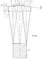
- the 1a and 1b illustrate the basic arrangement and Formation of the teeth on the saw blade. It is a leading tooth 1 and several follower teeth 2, 3, 4, 5, .. are provided. Of the Guide tooth 1 and the follower teeth 2, 3, .. are in one repeating group 6 arranged. Each group 6 represents one Sequence of teeth in which the teeth are directly on top of each other consequences. Groups 6 are also connected to each other.
- the follower teeth 2, 3, .. are each provided in an even number, whereby they are assigned to one another in pairs.
- the leading tooth 1 is always a straight, unrestrained tooth.
- the follow teeth 2, 3, 4, 5, .. are always set teeth, being the set in the tooth sequence alternately to the right and left or vice versa is carried out.
- the guide tooth 1 always has one greater tooth height than the secondary teeth 2, 3, ...
- Group 6 has a guide tooth 1 and two follower teeth 2 and 3.
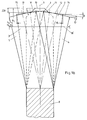
- Fig. 1b and 6 illustrate a group 6, which consists of a guide tooth 1 and four secondary teeth 2, 3, 4 and 5.
- the only single guide tooth 1 in a group 6 is a straight tooth, the tooth width of which corresponds to the width of the raw strip 7 or of the base body 8 of the saw blade.
- the guide tooth 1 has at its tooth tip a section 10 of its cutting edge which runs straight or perpendicular to the longitudinal center plane 9 and which, as can be seen in FIGS. 1a and 1b, is effective over its entire extent, ie does cutting work.
- this straight section 10 is adjoined to the right and left by an inclined section 11, which is also referred to as a phase.
- the section 11 extends below the cutting edges 12, 13, 14, 15 of the follower teeth 2, 3, 4, 5.
- the guide tooth 1 has a height h 1 .
- Subsequent teeth 2 and 3 have tooth heights h 2 and h 3, respectively.
- the tooth heights h 2 and h 3 can be slightly different. They are relatively close together.
- the tooth height h 1 of the guide tooth 1, on the other hand, is larger, so that there is a height difference ⁇ h between the tooth heights.
- the inclined sections 11 of the cutting edge on the guide tooth 1 are arranged at a phase angle 16, which can have values between 30 ° and 60 °.
- the setting of the secondary teeth 2, 3, .. is usually carried out in pairs. With each subsequent pair of follower teeth, the setting can increase in accordance with the desired widening of the cutting channel, but it can also remain the same if work in the depth of the cutting channel is to be emphasized with the appropriate feed. The set can become even smaller. It is also possible to design the setting of pairs of secondary teeth differently.
- the height difference ⁇ h and the phase angle 16 and the arrangement of the section 11 relative to the longitudinal center plane 9 are coordinated with one another such that the inner corners of the follower teeth 2, 3, .. are covered by the shape of the guide tooth 1 in the projection shown in FIG. 1 , so do no cutting work, so that only the outer corners of the secondary teeth 2, 3, .. work. As can be seen, this is reversed for the guide tooth 1.
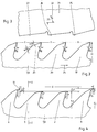
- raw teeth 19 and 20 (FIG. 2) are first produced on a raw strip 7, for example by a milling process.
- the raw teeth 19 and 20 can all have the same shape and the same raw tooth height H, as shown in FIG. 2.
- the raw teeth 19 and 20 can be arranged with a constant pitch t.
- the raw teeth 19 are already designed so that they have an assignment to the guide tooth 1, that is to say the raw teeth 19 are to be shaped into the guide teeth 1 during production, while the raw teeth 20 become secondary teeth 2, 3 , .. be reshaped.
- the raw teeth 20 can also have a different tooth height, in particular compared to the raw teeth 19.
- the raw teeth 19 and 20 are profiled with a matching positive raw chip angle gamma R and also have a first raw clearance angle ⁇ R1 and a second raw clearance angle ⁇ R2 .
- the implementation of these two different raw clearance angles is not absolutely necessary. It is also sufficient to create only one raw clearance angle by profiling.
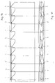
- Fig. 3 a compression punch 21 is illustrated, which extends with its length over the length of a group 6 of teeth and is driven in a stroke-like manner according to double arrow 22.
- the direction of movement according to double arrow 22 is at an acute compression angle 23 to the band running direction 24 of the saw blade.
- the compression stamp 21 has a first working surface 25, the arrangement and design of which is assigned to the plastic deformation of the tooth tip of the raw tooth 19 to produce the cutting edge and the rake angle gamma 1 and the clearance angle ⁇ 1 of the guide tooth 1, in such a way that the tooth tip of the Guide tooth 1 with its section 11 also receives the tooth height h 1 at the same time.
- the compression stamp 21 has a second working surface 26 which is designed and arranged for the plastic deformation of the tooth tip of the raw tooth 20 for the purpose of producing the following tooth 2.
- the tooth tip or the cutting edge 12 of the follower tooth 2 is produced by plastic deformation, the rake angle gamma R corresponding to the extent of the plastically deformed area at the tip of the tooth resulting in the rake angle gamma 2 on the follower tooth 2.
- the tooth tip is deformed so that the follower tooth 2 receives the tooth height h 2 , that is, the tooth difference ⁇ h to the tooth height h 1 of the guide tooth 1 is generated.
- the raw tooth 20 forming the follower tooth 2 according to FIG. 2 could already have a lower tooth height than the raw tooth 19 after profiling, so that the tooth difference ⁇ h results partly from profiling, partly from the plastic deformation.
- the compression ram 21 also has a third working surface 27, which is assigned to the plastic deformation of the second raw tooth 20 (FIG. 2) and thus to the generation of the following tooth 3.
- the follower tooth 3 is given a tooth height h 3 and a rake angle gamma 3 .
- the follower teeth 2 and 3 are not exactly identical to one another, but that, due to the manufacturing process, there are tolerable differences during the profiling process (FIG. 2), but above all also during the upsetting process (FIG. 3) in slight or deliberately larger differences, especially in the heights h 2 and h 3 and the rake angles gamma 2 and gamma 3 . From Fig.
- the first working surface 25 is arranged comparatively recessed relative to the other two working surfaces 26 and 27, so that during an upsetting process the working surfaces 26 and 27 first come into contact with the tooth tips of the raw teeth 20 during this contact between the working surface 25 and the tooth tip of the raw tooth 19 only after a certain free stroke. Nevertheless, a plastic deformation carried out in this way means a common plastic deformation of the raw teeth 19, 20 in the tooth group 6, which therefore takes place more or less simultaneously. On the other hand, it is conceivable to subdivide the upsetting punch 21 and to control or coordinate the strokes of the individual parts accordingly.
- the different plastic deformation of the tooth tips of the raw teeth 19 and 20 can take place, for example, by upsetting, but also by rolling, the shaping then taking place more or less in succession. It is also conceivable that the compression punch 21 has a longer working length, so that it can plastically deform the raw teeth of two successive groups 6 at the same time, for example.
- the different plastic deformation of the tooth tips of the raw teeth 19 and 20 is essential. In addition to the height difference, there is an increase in the positive raw rake angle, rake angles on the guide tooth 1 and the follow teeth 2, 3,... That cannot be produced by milling alone.
- the burr that is present after profiling is also flipped over at each tooth tip in the direction of the strip running direction 24, which increases the sharpness of each tooth.
- this has a positive effect in reducing the vibration behavior of the saw band, in such a way that a different chip scale frequency arises, which not only ensures smooth running of the Saw band contributes during use, but is also favorable for the edge retention and lifespan of the saw blade.
- Fig. 5 shows an enlarged view of a guide tooth 1 or a follower tooth 2, 3, .., which was milled with a raw rake angle gamma R and two clearance angles ⁇ R1 and ⁇ R2 and then plastically deformed such that a positive in the area of its tooth tip 28 Rake angle gamma and a clearance angle ⁇ was generated, the wedge angle of the tooth tip 28 being essentially maintained.
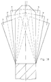
- FIG. 6 shows a side view of a second embodiment of the saw blade, similar to the view according to FIG. 4.
- Four follower teeth 2, 3, 4, 5 in group 6 are assigned to one guide tooth 1 here.
- a variable division t 1 , t 2 , t 3 , t 4 and t 5 is used.
- the teeth are plastically deformed in different ways. There are slight differences in height between the following teeth 2, 3, 4, 5, while the difference in height ⁇ h to the guide tooth 1 is of a different order of magnitude.
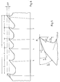
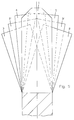
- the embodiment of the saw blade according to FIGS. 7 to 9 has a group 6 of seven teeth.
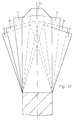
- Each group has 6 a guide tooth 1 and three pairs of follower teeth 2, 3; 4, 5 and 2 ', 3'. 7 and 8, auxiliary lines are shown.
- the auxiliary lines in FIG. 7 illustrate the different ones Tooth heights or height levels.
- the auxiliary lines in Fig. 8 clarify the different cabinet widths as an oversize Bandwidth. It can be seen that the pair of follower teeth 2, 3 the has the lowest tooth height and the largest cabinet width. This is also clear from the projection according to FIG. 9. It is also recognizable that the related secondary teeth 2 and 3 are not arranged in direct succession, but distributed anywhere in the group. In the pair of follower teeth 4 and 5 are those who have the following teeth have the greatest height.
- the height of the follower teeth 4 and 5 is not exactly the same, but forms a height difference ⁇ h to that Height of the guide teeth 1.
- the follower teeth 4 and 5 are on one first height level arranged opposite the guide teeth 1. It there are two more belonging to each other in group 6 Subsequent teeth 2 'and 3', the height of which is between the pairs of Subsequent teeth 2, 3 and 4, 5 is arranged.
- The is accordingly Cabinet width trained.
- the Grading step i.e. the height difference from a height level to the neighboring level in particular directly above the entire height grading can be carried out. That applies to the Cabinet width gradation.
- the arrangement of the teeth in the group is any. It makes sense to switch from one to the right set secondary tooth to a left set tooth etc. to maintain. But even this condition doesn't have to be fulfilled.
- Fig. 9 shows that it is in terms of the clearance of the Cut channel only depends on the projection of the teeth.
- the order of the teeth in the group is arbitrary. Every tooth only works with its cut edge section, the side protrudes beyond the projection of the other teeth. To this In this way, chips are removed in strip form from the cutting channel, that lie side by side in the projection and do not overlap each other. These stripes are due to the uniform gradation of the cabinet width equally wide. It is also recognizable as the load roughly evenly on everyone Teeth is distributed in the group.
- the production of the saw blade according to FIGS. 7 to 9 can be done in the way that first the profiling of all Raw teeth, for example, by milling with a rake angle of 10 ° and a matching raw tooth height. With this Profiling is only pre-formed the variable division. Then all teeth are plastically deformed, which are useful in a common deformation step for all teeth of the group is carried out, with the individual teeth, however, very different deformations arise.
- the guide tooth 1 is equipped with a Height difference of 0.15 mm compared to the raw tooth height and thereby gets a rake angle in the area of his Tip of z. B. 15 °.
- the tip of the guide tooth 1 is located with it at a first level.
- the pair of follower teeth 4, 5 is shaped down more than the guide tooth lands at a height level that is different from the height of the raw tooth differs by, for example, 0.20 mm.
- the following teeth 4, 5 get a rake angle of 17 °, for example Area of their tooth tips.
- the ones created during profiling Tolerances between the raw teeth are deliberately allowed or exploited, such that the secondary teeth 4, 5 after the plastic Deformation is not exactly at the same level and also do not have exactly the same rake angle. Also here differences, of course of a different magnitude, between the related teeth 4 and 5 authorized.
- the further pair of follower teeth 2 ', 3' is, for example formed from the raw tooth height to a further height level, which is 0.25 mm lower than the raw tooth height.
- the target rake angle here is, for example, 19 °.
- the Pair of follower teeth 2, 3, which after plastic deformation is located at the lowest level, has one Height difference of, for example, 0.30 mm to the raw tooth height.
- the target rake angle is 21 °.
- You can recognize this Example that the levels between the individual height levels are dimensioned the same, namely 0.05 mm.
- the grading of the rake angle the difference is 2 °. Of course you can too Appropriate tolerances are permitted here, for example of ⁇ 1 °.
- the pair of follower teeth 2, 3 is the one that was plastically deformed the most. If the material of the Band does not participate in such a deformation or the risk of If there are any fractures, it is recommended to adjust the raw tooth height Teeth that form the follower teeth 2, 3 already during profiling to be less than the raw tooth height of the remaining teeth, thus the relative deformation on the secondary teeth 2, 3 less becomes. The same can also be done for other pairs of secondary teeth be considered.
- 10 to 12 is another embodiment of a Saw blade shown with a group of eight teeth.
- many things are right with the embodiment 7 to 9, which is why reference is made to this can be.
- the even number of teeth in the group results, however, from the fact that the guide tooth 1 in the form of a another guide tooth 1 appears a second time in the group.
- the further guide tooth 1 can be approximately in the middle of the Group arranged.
- the teeth are with variable pitch arranged.
- Fig. 10 shows that the gradation of the height is not the same Steps, but carried out here in different steps is.
- the enlarged view leaves the mutual Recognize relation. Between the shaped guide teeth 1 and the largest follower teeth 4, 5 there is only a small difference in height.
- the respective height difference to the secondary teeth 2 ', 3 ' is already bigger and the last height difference from the follower teeth 2 ', 3' to the secondary teeth 2, 3 is even larger. It is but also possible, the height differences different and in to implement another order, for example falling or irregular.
- FIG. 11 shows an uneven, falling gradation of the cabinet width, their course can be seen better in the enlarged view is.
- the smallest step is between the secondary teeth 2 ', 3' and the follower teeth 2, 3, i.e. on the outside of the belt. With that the chips that clear the secondary teeth 2, 3 from the cutting channel, deliberately kept narrow. This improves the quality of the Surface of the cut workpiece.
- the grading of Cabinet width can also be increased or combined rising and falling.
- the projection representation of the teeth according to FIG. 12 is correct basically corresponds to the projection representation according to FIG. 9.
- the guide teeth 1 are identical and cover yourself. The different heights and the different Cabinet width grading can also be seen here.
- Group of teeth also made up of eight teeth, however, are here two different guide teeth 1 'and 1' 'immediately arranged one after the other at the beginning of the group.
- the pairs of Subsequent teeth are arranged one behind the other according to their height gradation.
- the pair of follower teeth follows 4, 5 with the greatest height of the follower teeth.
- Variable division is also implemented here. Of course, constant division could also be used be realized.
- the order is Any teeth in the group.
- the embodiment of the saw blade according to FIGS. 16 to 18 has nine teeth in the group.
- the guide tooth 1 is arranged three times in the group. From the follow teeth there are two between two guide teeth, whereby these are enclosed by two adjacent guide teeth Subsequent teeth belong to different pairs. But here too 18 matches the projection representation 9 in accordance with the drawing.
Landscapes
- Engineering & Computer Science (AREA)
- Mechanical Engineering (AREA)
- Milling Processes (AREA)
- Gear Processing (AREA)
- Sawing (AREA)
- Heat Treatment Of Articles (AREA)
- Component Parts Of Construction Machinery (AREA)
- Knives (AREA)
- Nonmetal Cutting Devices (AREA)
- Accessories And Tools For Shearing Machines (AREA)
Applications Claiming Priority (2)
| Application Number | Priority Date | Filing Date | Title |
|---|---|---|---|
| DE19739074 | 1997-09-08 | ||
| DE19739074A DE19739074B4 (de) | 1997-09-08 | 1997-09-08 | Sägeblatt und Verfahren zu seiner Herstellung |
Publications (3)
| Publication Number | Publication Date |
|---|---|
| EP0900616A2 true EP0900616A2 (fr) | 1999-03-10 |
| EP0900616A3 EP0900616A3 (fr) | 2001-04-25 |
| EP0900616B1 EP0900616B1 (fr) | 2004-06-02 |
Family
ID=7841445
Family Applications (1)
| Application Number | Title | Priority Date | Filing Date |
|---|---|---|---|
| EP98116700A Expired - Lifetime EP0900616B1 (fr) | 1997-09-08 | 1998-09-03 | Lame de scie à configuration de dents de sciage et procédé pour sa fabrication |
Country Status (9)
| Country | Link |
|---|---|
| US (1) | US6158324A (fr) |
| EP (1) | EP0900616B1 (fr) |
| JP (1) | JPH11147201A (fr) |
| AT (1) | ATE268241T1 (fr) |
| CA (1) | CA2246552C (fr) |
| DE (2) | DE19739074B4 (fr) |
| DK (1) | DK0900616T3 (fr) |
| ES (1) | ES2221104T3 (fr) |
| PT (1) | PT900616E (fr) |
Cited By (3)
| Publication number | Priority date | Publication date | Assignee | Title |
|---|---|---|---|---|
| WO2007128276A1 (fr) * | 2006-05-04 | 2007-11-15 | Leitz Gmbh & Co. Kg | Lame de scie circulaire pourvue de lames d'évacuation et procédé de fabrication desdites lames d'évacuation |
| WO2011038844A1 (fr) * | 2009-09-30 | 2011-04-07 | J.N. Eberle & Cie. Gmbh | Scie à ruban et lame de scie |
| CN102123810B (zh) * | 2008-08-20 | 2012-12-26 | 株式会社天田 | 锯片及其制造方法 |
Families Citing this family (54)
| Publication number | Priority date | Publication date | Assignee | Title |
|---|---|---|---|---|
| JP2001062629A (ja) * | 1999-06-22 | 2001-03-13 | Amada Co Ltd | 鋸 刃 |
| US6520722B2 (en) * | 1999-07-21 | 2003-02-18 | Simonds Industries, Inc. | Asymmetrical cutting tool tooth form |
| US6601495B2 (en) | 2000-07-18 | 2003-08-05 | American Saw & Mfg. Co., Inc. | Structural saw blade |
| US6588992B2 (en) | 2001-02-06 | 2003-07-08 | Black & Decker Inc. | Hole saw |
| US7036417B2 (en) | 2001-11-13 | 2006-05-02 | William George Alton | Bandsaw blade with cutting extensions |
| US20030200853A1 (en) * | 2002-04-26 | 2003-10-30 | Gongola Andrew G. | Tool element and marking system |
| FR2841806B1 (fr) * | 2002-07-04 | 2004-12-24 | Oca | Lame de scie avec une suite repetitive d'un train de dents |
| US7017465B2 (en) | 2002-07-29 | 2006-03-28 | L.S. Starrett Company | Cutting tool with grooved cutting edge |
| US7373857B2 (en) * | 2002-07-29 | 2008-05-20 | William Engineering Llc | Composite metal article and method of making |
| US7178441B2 (en) * | 2002-12-20 | 2007-02-20 | Kapman Ab | Versatile bandsaw blade |
| US6939092B2 (en) * | 2003-06-18 | 2005-09-06 | Irwin Industrial Tool Company | Sheet metal hole cutter |
| US7131365B2 (en) * | 2003-09-16 | 2006-11-07 | Irwin Industrial Tool Company | Multi-chip facet cutting saw blade and related method |
| US7225714B2 (en) * | 2004-12-22 | 2007-06-05 | Black & Decker Inc. | Tooth form design for reciprocating saw blade |
| US7658136B2 (en) * | 2004-12-22 | 2010-02-09 | Black & Decker Inc. | Hole saw blade |
| JP2005305639A (ja) * | 2004-04-16 | 2005-11-04 | Kapman Ab | 帯のこぎり歯及び帯のこぎり歯の製造方法 |
| EP1586401A1 (fr) * | 2004-04-16 | 2005-10-19 | Kapman AB | Lame de scie à ruban et procédé de fabrication d'une lame de scie à ruban |
| DE102004060972A1 (de) * | 2004-12-17 | 2006-07-20 | Irwin Industrial Tools Gmbh | Sägeblatt und Säge |
| US7264428B2 (en) * | 2005-05-19 | 2007-09-04 | Irwin Industrial Tool Company | Hole saw and cutter |
| US20070199416A1 (en) * | 2006-02-25 | 2007-08-30 | Cook James T | Band saw blade |
| WO2007098276A2 (fr) * | 2006-02-25 | 2007-08-30 | James Timothy Cook | Lame de scie a ruban |
| US8210081B2 (en) * | 2007-06-12 | 2012-07-03 | Irwin Industrial Tool Company | Reciprocating saw blade having variable-height teeth and related method |
| SE532472C2 (sv) * | 2008-05-06 | 2010-02-02 | Seco Tools Ab | Skärverktyg med skär uppvisande multipla skäreggar, och skär därför |
| US20110119934A1 (en) * | 2008-07-25 | 2011-05-26 | Bertsch Matthew T | Band saw |
| DE102008044108A1 (de) * | 2008-11-27 | 2010-06-02 | Robert Bosch Gmbh | Hubsägeblatt für Handhubsägemaschinen |
| JP5508531B2 (ja) * | 2009-07-27 | 2014-06-04 | アーウィン インダストリアル トゥール カンパニー | 単レベル目立てパターン及び複レベル目立てパターンを併含するピッチパターンに従うソーブレード及びそれに関連する方法 |
| US10189099B2 (en) | 2010-04-22 | 2019-01-29 | Milwaukee Electric Tool Corporation | Saw Blade |
| WO2011133864A2 (fr) | 2010-04-22 | 2011-10-27 | Milwaukee Electric Tool Corporation | Lame de scie |
| US9375796B2 (en) * | 2010-05-07 | 2016-06-28 | Irwin Industrial Tool Company | Saw blade with robust tooth form |
| USD642028S1 (en) | 2010-05-21 | 2011-07-26 | Irwin Industrial Tool Company | Reciprocating saw blade |
| US9248518B2 (en) * | 2010-06-30 | 2016-02-02 | Irwin Industrial Tool Company | Saw blade tooth form for abusive cutting applications |
| CA2749666C (fr) | 2010-08-20 | 2014-07-15 | Milwaukee Electric Tool Corporation | Lame de scie a mouvement alternatif |
| USD841417S1 (en) | 2011-04-22 | 2019-02-26 | Milwaukee Electric Tool Corporation | Saw blade |
| DE102011053720B4 (de) | 2011-09-16 | 2015-12-24 | WIKUS-Sägenfabrik Wilhelm H. Kullmann GmbH & Co. KG | Sägeblatt mit Leistungszähnen und Oberflächenzähnen |
| US9731365B2 (en) * | 2011-12-07 | 2017-08-15 | Irwin Industrial Tool Company | Saw blade with tooth form projection |
| JP5903345B2 (ja) * | 2012-07-17 | 2016-04-13 | 株式会社アマダホールディングス | 鋸刃各歯の最適配置方法及び鋸刃 |
| DE112013003582B4 (de) | 2012-07-18 | 2022-08-11 | Milwaukee Electric Tool Corp. | Zahnform für ein Schneidwerkzeug, wie etwa eine Lochsäge |
| CA2845968C (fr) | 2013-03-14 | 2016-07-26 | Irwin Industrial Tool Company | Lame de scie alternative a bord de coupe incurve |
| US9370834B2 (en) | 2013-03-14 | 2016-06-21 | Irwin Industrial Tool Company | Saw blade with feed limiter |
| USD732914S1 (en) * | 2013-11-13 | 2015-06-30 | Irwin Industrial Tool Company | Reciprocating saw blade |
| USD725450S1 (en) * | 2013-11-13 | 2015-03-31 | Irwin Industrial Tool Company | Reciprocating saw blade |
| DE102015116747B3 (de) | 2015-10-02 | 2017-03-30 | WIKUS-Sägenfabrik Wilhelm H. Kullmann GmbH & Co. KG | Sägeblatt mit einem Spanteilerzahn |
| AT517762A1 (de) * | 2015-10-14 | 2017-04-15 | Voestalpine Prec Strip Gmbh | Schneidwerkzeug zum Trennen von Flachmaterialien |
| JP6579913B2 (ja) * | 2015-10-26 | 2019-09-25 | マクセルホールディングス株式会社 | 回転刃、および回転刃を備えている小型電気機器 |
| US10384273B2 (en) * | 2016-08-24 | 2019-08-20 | The M.K. Morse Company | Hole saw |
| US10926343B2 (en) * | 2016-04-19 | 2021-02-23 | The M. K. Morse Company | Ground set saw blade |
| US10279408B2 (en) | 2016-04-19 | 2019-05-07 | The M. K. Morse Company | Ground set saw blade |
| US10940546B2 (en) | 2016-04-19 | 2021-03-09 | The M.K. Morse Company | Ground set hole saw |
| US10166612B2 (en) * | 2016-08-26 | 2019-01-01 | Irwin Industrial Tool Company | Tooth formations and arrangement for a saw blade |
| JP6337169B1 (ja) * | 2017-02-24 | 2018-06-06 | 株式会社アマダホールディングス | 硬質チップ帯鋸刃 |
| US11413693B2 (en) | 2017-05-16 | 2022-08-16 | Milwaukee Electric Tool Corporation | Saw blade |
| US10537951B2 (en) | 2017-08-16 | 2020-01-21 | Black & Decker Inc. | Band saw blade for cutting structural workpieces |
| US11524348B2 (en) | 2019-04-04 | 2022-12-13 | Black & Decker Inc. | Circular saw blade |
| CN114728349B (zh) * | 2019-11-14 | 2025-07-08 | 米沃奇电动工具公司 | 具有大的硬质合金悬突的孔锯 |
| US11986890B2 (en) * | 2022-02-07 | 2024-05-21 | The M.K. Morse Company | Carbide tip hole saw |
Family Cites Families (10)
| Publication number | Priority date | Publication date | Assignee | Title |
|---|---|---|---|---|
| JPS58137520A (ja) * | 1982-01-13 | 1983-08-16 | Amada Co Ltd | 鋸刃 |
| CH660326A5 (de) * | 1983-01-13 | 1987-04-15 | Tecno Zuerich Ag | Saegeblatt fuer die bearbeitung von holz oder aehnlichen werkstoffen. |
| CA1277573C (fr) * | 1985-04-03 | 1990-12-11 | Sumio Yoshida | Lame de scie |
| DE3711228A1 (de) * | 1987-04-03 | 1988-10-20 | Wagner Maschf Gustav | Schneidezahn sowie mit solchen schneidezaehnen versehene metallsaegen, insbesondere kreissaegeblaetter |
| US5331876A (en) * | 1992-07-30 | 1994-07-26 | Sandvik Ab | Saw blade for cutting metal |
| US5477763A (en) * | 1993-01-12 | 1995-12-26 | Wikus-Sagenfabrik, Wilhelm H. Kullmann | Saw blade |
| DE9311471U1 (de) * | 1993-01-13 | 1993-11-18 | Wilhelm H. Kullmann Wikus-Sägenfabrik, 34286 Spangenberg | Sägeblatt mit einem Grundkörper und ungeschränkten Zähnen |
| FR2707904B1 (fr) * | 1993-07-22 | 1995-09-29 | Manuf Forezienne Lames Sci | Lame de scie à ruban alternative ou circulaire pour le travail du bois et de ses dérivés. |
| US5410935A (en) * | 1993-11-01 | 1995-05-02 | American Saw & Mfg. Company | Band saw blade |
| US5803678A (en) * | 1995-06-20 | 1998-09-08 | American Saw & Mfg. Company | Hole cutting tools |
-
1997
- 1997-09-08 DE DE19739074A patent/DE19739074B4/de not_active Expired - Fee Related
-
1998
- 1998-09-03 DK DK98116700T patent/DK0900616T3/da active
- 1998-09-03 ES ES98116700T patent/ES2221104T3/es not_active Expired - Lifetime
- 1998-09-03 EP EP98116700A patent/EP0900616B1/fr not_active Expired - Lifetime
- 1998-09-03 DE DE59811500T patent/DE59811500D1/de not_active Expired - Lifetime
- 1998-09-03 AT AT98116700T patent/ATE268241T1/de active
- 1998-09-03 US US09/146,894 patent/US6158324A/en not_active Expired - Lifetime
- 1998-09-03 PT PT98116700T patent/PT900616E/pt unknown
- 1998-09-04 CA CA002246552A patent/CA2246552C/fr not_active Expired - Lifetime
- 1998-09-07 JP JP10253059A patent/JPH11147201A/ja active Pending
Cited By (3)
| Publication number | Priority date | Publication date | Assignee | Title |
|---|---|---|---|---|
| WO2007128276A1 (fr) * | 2006-05-04 | 2007-11-15 | Leitz Gmbh & Co. Kg | Lame de scie circulaire pourvue de lames d'évacuation et procédé de fabrication desdites lames d'évacuation |
| CN102123810B (zh) * | 2008-08-20 | 2012-12-26 | 株式会社天田 | 锯片及其制造方法 |
| WO2011038844A1 (fr) * | 2009-09-30 | 2011-04-07 | J.N. Eberle & Cie. Gmbh | Scie à ruban et lame de scie |
Also Published As
| Publication number | Publication date |
|---|---|
| JPH11147201A (ja) | 1999-06-02 |
| ATE268241T1 (de) | 2004-06-15 |
| DE19739074A1 (de) | 1999-03-18 |
| DK0900616T3 (da) | 2004-08-23 |
| ES2221104T3 (es) | 2004-12-16 |
| CA2246552C (fr) | 2005-08-02 |
| EP0900616A3 (fr) | 2001-04-25 |
| US6158324A (en) | 2000-12-12 |
| CA2246552A1 (fr) | 1999-03-08 |
| EP0900616B1 (fr) | 2004-06-02 |
| PT900616E (pt) | 2004-10-29 |
| DE19739074B4 (de) | 2005-07-07 |
| DE59811500D1 (de) | 2004-07-08 |
Similar Documents
| Publication | Publication Date | Title |
|---|---|---|
| EP0900616B1 (fr) | Lame de scie à configuration de dents de sciage et procédé pour sa fabrication | |
| EP0551104B1 (fr) | Lame de scie | |
| DE69423508T2 (de) | Verbessertes bandsägeblatt | |
| DE3940552B4 (de) | Sägeblatt | |
| DE19963396C2 (de) | Sägeblatt mit einem Grundkörper und ungeschränkten Zähnen | |
| EP2277652B1 (fr) | Lame de scie ayant des dents dotées d'un élément de déformation de copeaux | |
| DE69901202T2 (de) | Bandsägeblatt mit geraden Zähnen sowie geschränkten Zähnen | |
| EP0610647B1 (fr) | Lame de scie avec base et denture alignée | |
| DE3307170A1 (de) | Saegeblatt | |
| DE2100204C3 (de) | Vorrichtung zum Herstellen selbstschneidender Schrauben durch Walzen eines Gewindes in einen Rohling | |
| EP2570216B1 (fr) | Lame de scie avec dents de surface et dents de puissance | |
| DE3346462C2 (de) | Verfahren zur Herstellung von Zähnen eines Zahnstangengliedes | |
| EP2861368A1 (fr) | Procédé pour générer une denture et machine à former les dentures fonctionnant au moyen de ce procédé | |
| DE2455574A1 (de) | Verfahren zur herstellung eines haarschneidekammes | |
| DE2946949C1 (de) | Einteiliger Raeumzahnwaelzfraeser | |
| EP1160040A1 (fr) | Outil de brochage interne | |
| DE19942272C1 (de) | Fräswerkzeug | |
| EP0310693A1 (fr) | Méthode de fabrication de lames de coupe | |
| EP4405128A1 (fr) | Procédé de fabrication d'un outil de fraisage, outil de fraisage et procédé de production de dents d'engrenage par fraisage au moyen d'un outil de fraisage de ce type | |
| EP4140672A1 (fr) | Maillon d'entraînement pour une lame de coupe et agencement de plusieurs maillons d'entraînement pour unelampe de coupe | |
| CH642286A5 (de) | Herstellungsverfahren eines schiffchens fuer stick- oder steppmaschinen und nach diesem verfahren hergestelltes schiffchen. | |
| DE102004023961A1 (de) | Verfahren zur Herstellung einer Turbomolekularpumpen-Statorstufe | |
| DE29818217U1 (de) | Trennwerkzeug, insbesondere Sägeblatt | |
| DE1938994A1 (de) | Verfahren zum Ausschneiden von Formstuecken aus fortlaufenden Profilstreifen,insbesondere zur Herstellung von Tuerscharnierhaelften | |
| DE29915589U1 (de) | Bearbeitungswerkzeug, insbesondere Fräswerkzeug oder Räumwerkzeug |
Legal Events
| Date | Code | Title | Description |
|---|---|---|---|
| PUAI | Public reference made under article 153(3) epc to a published international application that has entered the european phase |
Free format text: ORIGINAL CODE: 0009012 |
|
| AK | Designated contracting states |
Kind code of ref document: A2 Designated state(s): AT BE CH DE DK ES FR GB IE IT LI NL PT SE |
|
| AX | Request for extension of the european patent |
Free format text: AL;LT;LV;MK;RO;SI |
|
| RAP1 | Party data changed (applicant data changed or rights of an application transferred) |
Owner name: WIKUS-SAEGENFABRIK WILHELM H. KULLMANN GMBH & CO. |
|
| PUAL | Search report despatched |
Free format text: ORIGINAL CODE: 0009013 |
|
| AK | Designated contracting states |
Kind code of ref document: A3 Designated state(s): AT BE CH CY DE DK ES FI FR GB GR IE IT LI LU MC NL PT SE |
|
| AX | Request for extension of the european patent |
Free format text: AL;LT;LV;MK;RO;SI |
|
| RIC1 | Information provided on ipc code assigned before grant |
Free format text: 7B 23D 61/02 A, 7B 23D 61/12 B |
|
| 17P | Request for examination filed |
Effective date: 20010707 |
|
| AKX | Designation fees paid |
Free format text: AT BE CH DE DK ES FR GB IE IT LI NL PT SE |
|
| GRAP | Despatch of communication of intention to grant a patent |
Free format text: ORIGINAL CODE: EPIDOSNIGR1 |
|
| GRAS | Grant fee paid |
Free format text: ORIGINAL CODE: EPIDOSNIGR3 |
|
| GRAA | (expected) grant |
Free format text: ORIGINAL CODE: 0009210 |
|
| AK | Designated contracting states |
Kind code of ref document: B1 Designated state(s): AT BE CH DE DK ES FR GB IE IT LI NL PT SE |
|
| REG | Reference to a national code |
Ref country code: GB Ref legal event code: FG4D Free format text: NOT ENGLISH |
|
| REG | Reference to a national code |
Ref country code: CH Ref legal event code: NV Representative=s name: RIEDERER HASLER & PARTNER PATENTANWAELTE AG Ref country code: CH Ref legal event code: EP |
|
| GBT | Gb: translation of ep patent filed (gb section 77(6)(a)/1977) |
Effective date: 20040602 |
|
| REF | Corresponds to: |
Ref document number: 59811500 Country of ref document: DE Date of ref document: 20040708 Kind code of ref document: P |
|
| REG | Reference to a national code |
Ref country code: IE Ref legal event code: FG4D Free format text: GERMAN |
|
| REG | Reference to a national code |
Ref country code: DK Ref legal event code: T3 |
|
| REG | Reference to a national code |
Ref country code: SE Ref legal event code: TRGR |
|
| REG | Reference to a national code |
Ref country code: PT Ref legal event code: SC4A Free format text: AVAILABILITY OF NATIONAL TRANSLATION Effective date: 20040831 |
|
| REG | Reference to a national code |
Ref country code: ES Ref legal event code: FG2A Ref document number: 2221104 Country of ref document: ES Kind code of ref document: T3 |
|
| ET | Fr: translation filed | ||
| PLBE | No opposition filed within time limit |
Free format text: ORIGINAL CODE: 0009261 |
|
| STAA | Information on the status of an ep patent application or granted ep patent |
Free format text: STATUS: NO OPPOSITION FILED WITHIN TIME LIMIT |
|
| 26N | No opposition filed |
Effective date: 20050303 |
|
| REG | Reference to a national code |
Ref country code: FR Ref legal event code: PLFP Year of fee payment: 19 |
|
| REG | Reference to a national code |
Ref country code: FR Ref legal event code: PLFP Year of fee payment: 20 |
|
| PGFP | Annual fee paid to national office [announced via postgrant information from national office to epo] |
Ref country code: IT Payment date: 20170926 Year of fee payment: 20 Ref country code: GB Payment date: 20170925 Year of fee payment: 20 Ref country code: DE Payment date: 20170704 Year of fee payment: 20 Ref country code: FR Payment date: 20170925 Year of fee payment: 20 Ref country code: CH Payment date: 20170925 Year of fee payment: 20 |
|
| PGFP | Annual fee paid to national office [announced via postgrant information from national office to epo] |
Ref country code: PT Payment date: 20170824 Year of fee payment: 20 Ref country code: DK Payment date: 20170925 Year of fee payment: 20 Ref country code: SE Payment date: 20170925 Year of fee payment: 20 Ref country code: IE Payment date: 20170921 Year of fee payment: 20 Ref country code: BE Payment date: 20170925 Year of fee payment: 20 Ref country code: NL Payment date: 20170925 Year of fee payment: 20 Ref country code: AT Payment date: 20170920 Year of fee payment: 20 |
|
| PGFP | Annual fee paid to national office [announced via postgrant information from national office to epo] |
Ref country code: ES Payment date: 20171003 Year of fee payment: 20 |
|
| REG | Reference to a national code |
Ref country code: DE Ref legal event code: R071 Ref document number: 59811500 Country of ref document: DE |
|
| REG | Reference to a national code |
Ref country code: NL Ref legal event code: MK Effective date: 20180902 |
|
| REG | Reference to a national code |
Ref country code: DK Ref legal event code: EUP Effective date: 20180903 |
|
| REG | Reference to a national code |
Ref country code: CH Ref legal event code: PL |
|
| REG | Reference to a national code |
Ref country code: GB Ref legal event code: PE20 Expiry date: 20180902 |
|
| REG | Reference to a national code |
Ref country code: AT Ref legal event code: MK07 Ref document number: 268241 Country of ref document: AT Kind code of ref document: T Effective date: 20180903 |
|
| REG | Reference to a national code |
Ref country code: IE Ref legal event code: MK9A |
|
| REG | Reference to a national code |
Ref country code: BE Ref legal event code: MK Effective date: 20180903 |
|
| PG25 | Lapsed in a contracting state [announced via postgrant information from national office to epo] |
Ref country code: GB Free format text: LAPSE BECAUSE OF EXPIRATION OF PROTECTION Effective date: 20180902 |
|
| PG25 | Lapsed in a contracting state [announced via postgrant information from national office to epo] |
Ref country code: IE Free format text: LAPSE BECAUSE OF EXPIRATION OF PROTECTION Effective date: 20180903 Ref country code: PT Free format text: LAPSE BECAUSE OF EXPIRATION OF PROTECTION Effective date: 20181003 |
|
| REG | Reference to a national code |
Ref country code: ES Ref legal event code: FD2A Effective date: 20200724 |
|
| PG25 | Lapsed in a contracting state [announced via postgrant information from national office to epo] |
Ref country code: ES Free format text: LAPSE BECAUSE OF EXPIRATION OF PROTECTION Effective date: 20180904 |